EP0329517A1 - Cable-stayed bridge and method of constructing it - Google Patents
Cable-stayed bridge and method of constructing it Download PDFInfo
- Publication number
- EP0329517A1 EP0329517A1 EP89400312A EP89400312A EP0329517A1 EP 0329517 A1 EP0329517 A1 EP 0329517A1 EP 89400312 A EP89400312 A EP 89400312A EP 89400312 A EP89400312 A EP 89400312A EP 0329517 A1 EP0329517 A1 EP 0329517A1
- Authority
- EP
- European Patent Office
- Prior art keywords
- deck
- pylon
- cable
- bridge according
- bridge
- Prior art date
- Legal status (The legal status is an assumption and is not a legal conclusion. Google has not performed a legal analysis and makes no representation as to the accuracy of the status listed.)
- Granted
Links
Images


Classifications
-
- E—FIXED CONSTRUCTIONS
- E01—CONSTRUCTION OF ROADS, RAILWAYS, OR BRIDGES
- E01D—CONSTRUCTION OF BRIDGES, ELEVATED ROADWAYS OR VIADUCTS; ASSEMBLY OF BRIDGES
- E01D11/00—Suspension or cable-stayed bridges
- E01D11/04—Cable-stayed bridges
-
- E—FIXED CONSTRUCTIONS
- E01—CONSTRUCTION OF ROADS, RAILWAYS, OR BRIDGES
- E01D—CONSTRUCTION OF BRIDGES, ELEVATED ROADWAYS OR VIADUCTS; ASSEMBLY OF BRIDGES
- E01D19/00—Structural or constructional details of bridges
- E01D19/14—Towers; Anchors ; Connection of cables to bridge parts; Saddle supports
Definitions
- the present invention relates to cable-stayed bridges with a concrete deck, intended in particular to cross spans of the order of 80 to 250 m, and the construction of such bridges.
- the deck of such cable-stayed bridges consists of a concrete box suspended at regular intervals by guy lines which themselves transmit the load to pylons located on either side of the breach. to cross.
- the shrouds can be located in the median plane of the structure, between the traffic lanes. The stability of the deck under the influence of asymmetrical loads when only one traffic lane is loaded is then ensured by the torsional resistance of the box.
- the shrouds are placed on either side of the deck in two vertical planes, or oblique and also inclined on either side of the axis of the structure to allow the shrouds to converge in a single point on the pylon head.
- the deck In the case of this double lateral suspension, recent embodiments have appeared to simplify the construction of the deck and reduce the cost thereof.
- the deck When the main span is sufficiently small (of the order of 100 to 150 m maximum) the deck then consists of a simple solid concrete slab suspended along its two lateral edges.
- the limits of use of this solution are given by the excessive flexibility of the deck vis-à-vis the risk of general buckling or for the operation of the structure.
- the low transverse rigidity of the slab does not always ensure the stability of the structure vis-à-vis the wind in a satisfactory manner.
- the deck was made up of a slab ribbed in the transverse direction and provided with longitudinal edge beams in which the shrouds are anchored.
- aprons are in principle easier to produce than box aprons. They do not, however, have the same longitudinal rigidity in flexion and above all their torsional inertia is negligible. The effects of accidental phenomena such as exceptional wind gusts, impact of a vehicle against a shroud, therefore have much more serious consequences on these structures.
- the decks whether in boxes or formed of a ribbed slab, can be formed of successive prefabricated elements assembled to each other in the longitudinal direction. This less expensive method of construction does not appreciably affect the rigidity and the above remarks remain valid in this case.
- the object of the present invention is to overcome the limitations or inadequacies recalled above, authorizing the production of works whose rigidity is comparable to box decks, while retaining the simplicity of form and construction of the decks in solid or ribbed slab. .
- the invention provides a cable-stayed bridge, comprising: - at least one deck formed by a series of at least partially prefabricated elements, each element extending over the width of the deck and over part of its length, - a pylon carried by a pile, and the top of which supports a series of shrouds supporting the deck, which has the particularity that each element has interior recesses elongated in the transverse direction, and has a vertical cross section which is roughly symmetrical with respect to to a horizontal plane.
- the bridge is made up of a series of adjoining transverse boxes, and no longer of longitudinal boxes or of flat, simple or ribbed slabs.
- the result, for equal weight, is a very high torsional rigidity of the apron.
- the elements are joined together to constitute the deck is made by all conventional means, and in particular by longitudinal prestressing cables extending over several successive elements and / or over the entire length of the deck.
- each of these is a prefabricated one-piece element formed by a lower table and an upper table which carries the floor, separated by interior voids extending over a large part of the transverse dimension of the element, the two tables being joined together by walls and, optionally, longitudinal and transverse partitions.
- each of these comprises a prefabricated part consisting of a lower table and transverse and longitudinal vertical walls or partitions, horizontal slabs resting on said walls or partitions, and a continuous upper slab the along the deck, cast on the slabs and carrying the floor.
- the first embodiment provides time and productivity savings thanks to further prefabrication.
- the second embodiment allows easy replacement of the floor slabs if necessary, which is advantageous especially in countries with a harsh climate, where it is subjected to the attack of de-icing products.
- the batteries Due to the high torsional rigidity of the deck, the corresponding forces are transmitted at a distance, in particular to the abutments and the piles. It is advantageous to give the batteries a structure which makes them capable of absorbing these forces. For this, provision can be made for the stack carrying the pylon to extend upwards to the deck and support both at least part of the deck and the pylon.
- each stack to carry the part of the deck or decks which is closest to the longitudinal axial plane of the bridge and the part of the decks which is the most separated from the longitudinal axial plane of the bridge is supported by additional stay cables situated approximately in a transverse vertical plane and connecting the deck to the summit area of the pylon.
- This structure is formed in a transverse plane, and is therefore perpendicular to the longitudinal triangles formed by the deck, the pylon and the conventional shrouds.
- At least one of said additional stay cables is deflected at the top of the pylon and comes to hang on the opposite edge of the deck.
- the fixing and tensioning of the additional shrouds is thus done at the deck, which facilitates assembly.
- these are hinged together or are rigidly linked together in line with the pile, and at least one of said additional stay cables is diverted to the top of the pylon and clings to the opposite edge of the same deck, near the longitudinal axial plane of the bridge.
- the head of the pylon is of increasing complexity with the number of layers of cables, in particular if it must support the additional cables mentioned above, and which are in planes perpendicular to these layers.
- the pylon head is a metallic piece which has, in its upper part, a saddle-shaped surface and on which the deck support struts resting side by side are deflected to go to two attachment points located on the apron approximately symmetrically with respect to the pylon, the middle part of said metal part having a cavity which contains the means for anchoring or deflecting the additional stays.
- the pylon head comprises for each cable ply, a deflection assembly situated in the plane of this ply and comprising at least one part crossed by a number of deflection passages equal to the number of shrouds, these passages being superimposed on each other, and the means for anchoring or deflecting the additional stay cables being placed between the deflection assemblies.
- the means for securing a stay cable with an element of the apron comprise a plate, flat as a whole, bearing by a first face against the apron, and bearing on the second face means for anchoring the guy, means for preventing sliding of said plate on the deck, and at least one prestressing cable, or an anchoring rod, directed approximately perpendicular to the plane of said plate, this cable passing through said plate and being retained by abutment against it, and crossing the apron to be in abutment against the opposite side of the apron.
- the deck has a flat support surface for the plate, this flat surface being parallel to the stay and to the longitudinal axis of the bridge, with a central hollow part, the plate carries, on its face in contact with said bearing surface, a projection which penetrates into said hollow part and which contains the means for hooking said prestressing cable, and the prestressing cable enters the apron at the bottom of said hollow part and will hang on the transversely opposite edge of the deck.
- the edges of the prefabricated elements all have parallel bearing surfaces, and making with the vertical the same angle as the corresponding cable ply.
- the orientation of the metal anchoring part is the only difference from one prefabricated element to another, in the event that this part is put in place during casting.
- the plate is intended to be supported on a horizontal surface of the deck and bears on the face opposite to the deck, fittings for hanging a shroud obliquely to the horizontal, and the prestressing cable or cables or anchor rods pass through the deck down.
- This embodiment saves space in the transverse direction, it facilitates assembly, control and possible replacements.
- the metal attachment parts must be individualized, unless a pivot system is used.
- the bridge structure according to the invention allows a particularly advantageous construction method.
- a provisional framework is put in place fixed on a part of the deck already built and supported by the shrouds, this frame advancing in cantilever beyond said already constructed part and being supported by a mounting cable. connecting the top of the pylon to the end of the provisional frame furthest from the part already built, and said provisional frame is used to put in place and fix new deck elements, the length of the mounting cable being modified when the temporary frame is moved.
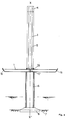
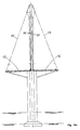
- Figure 1 shows a cable-stayed bridge, comprising an apron 1, resting at its ends on end piers 2, and supported in its central part by stay cables 3, which connect it to the head 4 of two pylons 5, carried by batteries 6, themselves grounded 7.
- FIG. 2 shows a cross section of a bridge according to the invention, according to its simplest embodiment: the bridge comprises a deck 1, arranged symmetrically with respect to the transverse axial plane XX 'of the structure.
- the deck is supported by two substantially vertical stay cables 3 which connect the pylon head to the deck 1 in its region closest to the axial plane XX ′.
- the deck 1 is formed of a series of hollow transverse structures, which gives them great rigidity in bending.
- the bending forces are mainly supported by the abutments, and incidentally by the piles 6 and the cables 3.
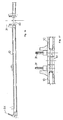
- Figure 3 shows a longitudinal section of an apron element 10, the assembly of similar elements constituting the apron 1. It is a prefabricated element comprising a lower table 11 and an upper table 12, the latter supporting pavement. Tables 11 and 12 are joined by transverse walls 13, as well as by an intermediate partition 14. The number of intermediate partitions 14 is not fixed, it may depend on the dimensions of the element 10. The inter partition mediary 14 may not even exist. Between the walls 13 and the intermediate partition 14, there are voids 15, which serve to reduce the weight of the element and to improve the efficiency of its load-bearing section with respect to the longitudinal flexions of the structure. It will be observed that the section of the deck is symmetrical with respect to a horizontal plane.
- the voids 15 extend transversely to the edge walls 16 (FIG. 2), being only interrupted by a central partition 17 which reinforces the rigidity of the element in the longitudinal direction.
- the transverse resistance of the element is ensured by reinforcements 18, which can be conventional passive reinforcements, pre-tensioned adherent prestressing reinforcements, or post-tensioned prestressing reinforcements having a layout adapted to bending stresses, or all combinations of the three types of reinforcement. Only a small number of these frames have been shown in FIG. 3.
- the deck elements 10 are supported on each other, and held by longitudinal prestressing cables, not shown.
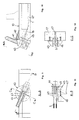
- FIGS. 4, 4a and 5 illustrate the method of connecting the shrouds 3 with the decks 1A and 1B of FIG. 2.
- a hooking piece 20 comprises a support plate 21, which carries on its upper face fittings 22, 23, welded to said plate 21, and oriented obliquely so that their core is parallel to the direction of the stay 3.
- the fittings 22, 23 hold the stay 3 by means of a stop piece 24, which cooperates with a clamping head 25 of the shroud.
- the plate 21 On its lower face, the plate 21 carries a frustoconical projection 26, which penetrates into a cavity of the same shape provided in the longitudinal wall 16 of an apron element 10.
- anchor rods 27 which are put under prestressing by bearing on the underside of the deck. These tie rods are shown vertical, but can be obliques.
- the forces transmitted by the stay 3 to the deck can be analyzed as comprising a vertical component, which is transmitted to the deck via the plate 21 and the tie rods 27, and a horizontal component, which is transmitted to the deck by the intermediate of the plate 21 and the projection 26, which plays the role of an anchoring key.
- FIG. 5 also shows barriers 28 which separate the vehicles from the hooking devices. The spacing between these two barriers 28 determines the free space for the base of the pylon as can be seen in FIG. 2.
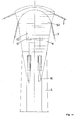
- Figures 6 and 7 relate to another embodiment.
- the suspension of the deck is ensured by two plies of guy wires 3 anchored on the banks and contained in two oblique planes whose intersection is substantially at the upper level of the pylon 4.
- the entire load of the deck 1 is transmitted to the stack 6 and to the foundations by the central pylon 4, the shapes of which are chosen to have maximum longitudinal inertia at the deck and maximum transverse inertia at its top.
- the shrouds 3 neighboring the pylon cooperate in the resistance of the structure vis-à-vis the horizontal forces.
- Special stabilizing shrouds 30 are also provided for this purpose in the transverse plane passing through the axis of the pylon.
- the apron is stiffened as necessary in this plane by pins or spacers 31 joining the edges of the apron to the stack 6.
- FIG. 8 is a longitudinal section which shows a variant of FIG. 3.
- each deck element 10 consisting of the lower slab 18 and walls or partitions 13 to 16, which constitute cores, is prefabricated. After installation in the structure, pre-slabs 32 are laid and the upper slab 33 carrying the floor is poured in place.
- Figures 9 to 12 relate to a device for anchoring the shrouds on the outer edges, or edges of the deck.
- An anchoring piece 40 comprises a plate 41, of generally circular shape, which comes to bear on a circular surface 42, provided during the making of the deck elements 10.
- the surface 42 is oblique to the vertical and made with it has the same angle as the ply of the shrouds 3.
- the plate 41 On its outer face, the plate 41 carries fittings 43, arranged perpendicular to the plate 41 and which carry the attachment system 44 and tensioning of the shroud 3. On its underside, the plate 41 carries a frustoconical projection 45, which penetrates into a corresponding cavity of the bearing element. In the projection 45 is housed the hooking means 46 of a prestressing cable 47, also visible in Figure 8.
- the cable 47 which is supported on the outer longitudinal wall 16 which forms the edge of the deck, crosses it and then enters the lower slab 11, and is connected, on the opposite side of the deck, to another hooking piece 40, or to any support means on the opposite edge of the 'element.
- Figures 13 and 14 show the detail of the head 4 of the pylon 5.
- the shrouds contained in the two lateral plies are arranged symmetrically with respect to the mean plane of the structure.
- Each shroud 3 is in fact continuous between the central span and the shore span, the change of direction to the right of the pylon taking place on a metal saddle 50 allowing the classification of the shrouds 3 next to each other.
- the special stays 30 for stabilizing the pylon are anchored to the top of the latter by known means 51, housed in a niche 52 placed below the saddle 50.
- a special saddle could also be provided for these particular stays.
- Figures 15a and 15b and 16 relate to a third embodiment of the invention.
- Each deck is suspended externally from a series of 3X oblique stays and in the center from a series of 3Y vertical stays.
- articulated connecting rods 60 bring the decks together in the horizontal direction to balance the horizontal component of the forces in the shrouds of the two edge plies.
- FIGS. 15 to 16 With its four plies of shrouds, presents a difficulty as regards the head of the pylon. Indeed, housing side by side the shrouds of the four layers leads to a very large width, in the transverse direction, of this head.
- a different pylon head structure illustrated in FIGS. 18 and 19 has been developed.
- Metal parts 70 to 73 each in the form of a bar pierced with a series of successive holes, are mounted on a frame 74, to form a sort of conical fan, diverging upwards, resting on the top of the pylon 5.
- the cables 3X of an oblique layer pass successively through a hole in each of the parts 70 to 73, these holes draw a broken line corresponding to the desired deviation of the cable.
- the inclination of these parts with respect to the vertical is such that they are contained in the plane of the web of the 3X shrouds.
- a second series of parts 70 to 73 is disposed in the same way to support 3X shrouds of the symmetrical oblique sheet.
- Other similar parts, of which only 75 is shown, are arranged in a plane about vertical longitudinal to receive the shrouds 3Y of the central layers.
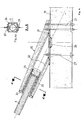
- FIGS 20 and 21 illustrate part of the deck construction.
- the deck is built by successive cantilevers symmetrically with respect to the pylon.
- the distance between the shrouds is subdivided into two or three elements 10.
- a frame 80 anchored at the rear in the deck already built carries a lifting winch 81 which makes it possible to place each of the elements prefabricated and temporarily immobilized. Due to the relative flexibility of the deck, the application of the weight of these prefabricated elements before implementation of the guy line 3 may create significant temporary stresses. This situation is remedied by suspending the front part of the mounting beam from the main pylon by means of a mounting cable 82 of progressively increasing length.
- FIG. 21 shows an apron element 10 being assembled, arrow 83, to be put in place.
- Figure 22 shows the situation after the installation of this element. After pouring the joints between elements and setting up the prestressing and new ones shrouds 3A, the mounting cable 82 is relaxed to advance the frame 80 according to arrow 84.
Abstract
Description
La présente invention concerne les ponts à haubans, à tablier en béton, destinés notamment à franchir des portées de l'ordre de 80 à 250 m, et la construction de tels ponts.The present invention relates to cable-stayed bridges with a concrete deck, intended in particular to cross spans of the order of 80 to 250 m, and the construction of such bridges.
Selon l'état actuel de la technique, le tablier de tels ponts haubanés est constitué d'un caisson en béton suspendu à intervalles réguliers par des haubans qui transmettent eux-mêmes la charge à des pylônes situés de part et d'autre de la brèche à franchir.According to the current state of the art, the deck of such cable-stayed bridges consists of a concrete box suspended at regular intervals by guy lines which themselves transmit the load to pylons located on either side of the breach. to cross.
Les haubans peuvent être situés dans le plan médian de l'ouvrage, entre les voies de circulation. La stabilité du tablier sous l'influence des charges dissymétriques lorsqu'une seule voie de circulation est chargée est alors assurée par la résistance à la torsion du caisson.The shrouds can be located in the median plane of the structure, between the traffic lanes. The stability of the deck under the influence of asymmetrical loads when only one traffic lane is loaded is then ensured by the torsional resistance of the box.
Sous une autre forme connue, les haubans sont placés de part et d'autre du tablier dans deux plans verticaux, ou obliques et également inclinés de part et d'autre de l'axe de l'ouvrage pour permettre aux haubans de converger en un point unique sur la tête du pylône.In another known form, the shrouds are placed on either side of the deck in two vertical planes, or oblique and also inclined on either side of the axis of the structure to allow the shrouds to converge in a single point on the pylon head.
Dans le cas de cette double suspension latérale, des réalisations récentes sont apparues pour simplifier la construction du tablier et en réduire le coût. Lorsque la portée principale est suffisamment faible (de l'ordre de 100 à 150 m maximum) le tablier est alors constitué d'une simple dalle pleine en béton suspendue le long de ses deux bords latéraux. Les limites d'utilisation de cette solution sont données par l'excessive flexibilité du tablier vis-à-vis du risque de flambement général ou pour l'exploitation de l'ouvrage. En outre, la faible rigidité transversale de la dalle n'assure pas toujours la stabilité de l'ouvrage vis-à-vis du vent de façon satisfaisante.In the case of this double lateral suspension, recent embodiments have appeared to simplify the construction of the deck and reduce the cost thereof. When the main span is sufficiently small (of the order of 100 to 150 m maximum) the deck then consists of a simple solid concrete slab suspended along its two lateral edges. The limits of use of this solution are given by the excessive flexibility of the deck vis-à-vis the risk of general buckling or for the operation of the structure. In addition, the low transverse rigidity of the slab does not always ensure the stability of the structure vis-à-vis the wind in a satisfactory manner.
Pour des portées plus grandes (de 100 à 300 m par exemple), le tablier a été constitué d'une dalle nervurée dans le sens transversal et munie de poutres de rive longitudinales dans lesquelles s'ancrent les haubans.For larger spans (from 100 to 300 m for example), the deck was made up of a slab ribbed in the transverse direction and provided with longitudinal edge beams in which the shrouds are anchored.
De tels tabliers sont en principe plus faciles à réaliser que des tabliers en caisson. Ils ne présentent toutefois pas la même rigidité longitudinale à la flexion et surtout leur inertie de torsion est négligeable. Les effets de phénomènes accidentels tels que rafales de vent exceptionnelles, choc d'un véhicule contre un hauban, ont donc sur ces ouvrages des conséquence beaucoup plus graves.Such aprons are in principle easier to produce than box aprons. They do not, however, have the same longitudinal rigidity in flexion and above all their torsional inertia is negligible. The effects of accidental phenomena such as exceptional wind gusts, impact of a vehicle against a shroud, therefore have much more serious consequences on these structures.
D'un autre côté, les tabliers, qu'ils soient en caissons ou formés d'une dalle nervurée, peuvent être formés d'éléments préfabriqués successifs assemblés les uns aux autres dans le sens longitudinal. Ce mode de construction, moins coûteux, n'affecte pas sensiblement la rigidité et les remarques ci-dessus demeurent valables dans ce cas.On the other hand, the decks, whether in boxes or formed of a ribbed slab, can be formed of successive prefabricated elements assembled to each other in the longitudinal direction. This less expensive method of construction does not appreciably affect the rigidity and the above remarks remain valid in this case.
La présente invention a pour objet de pallier les limitations ou insuffisances rappelées ci-dessus, autorisant la réalisation d'ouvrages dont la rigidité soit comparable aux tabliers à caissons, tout en conservant la simplicité de forme et de construction des tabliers en dalle pleine ou nervurée.The object of the present invention is to overcome the limitations or inadequacies recalled above, authorizing the production of works whose rigidity is comparable to box decks, while retaining the simplicity of form and construction of the decks in solid or ribbed slab. .
Pour obtenir ce résultat, l'invention fournit un pont haubané, comprenant :
- au moins un tablier formé d'une série d'éléments au moins partiellement préfabriqués, chaque élément s'étendant sur la largeur du tablier et sur une partie de sa longueur,
- un pylône porté par une pile, et dont le sommet soutient une série de haubans supportant le tablier, qui présente pour particularité que chaque élément présente des évidements intérieurs allongés dans le sens transversal, et a une section verticale transversale à peu près symétrique par rapport à un plan horizontal.To obtain this result, the invention provides a cable-stayed bridge, comprising:
- at least one deck formed by a series of at least partially prefabricated elements, each element extending over the width of the deck and over part of its length,
- a pylon carried by a pile, and the top of which supports a series of shrouds supporting the deck, which has the particularity that each element has interior recesses elongated in the transverse direction, and has a vertical cross section which is roughly symmetrical with respect to to a horizontal plane.
Ainsi, la différence principale avec les structures de tabliers classiques réside dans le fait que le pont est constitué d'une série de caissons transversaux accolés, et non plus de caissons longitudinaux ou de dalles planes, simples ou nervurées. Il en résulte, à poids égal, une très grande rigidité du tablier à la torsion.Thus, the main difference with conventional deck structures lies in the fact that the bridge is made up of a series of adjoining transverse boxes, and no longer of longitudinal boxes or of flat, simple or ribbed slabs. The result, for equal weight, is a very high torsional rigidity of the apron.
La solidarisation des éléments entre eux pour constituer le tablier est faite par tous moyens classiques, et notamment par des câbles de précontrainte longitudinaux s'étendant sur plusieurs éléments successifs et/ou sur toute la longueur du tablier.The elements are joined together to constitute the deck is made by all conventional means, and in particular by longitudinal prestressing cables extending over several successive elements and / or over the entire length of the deck.
Suivant un premier mode de réalisation des éléments, chacun de ceux-ci est un élément préfabriqué d'une seule pièce formé d'une table inférieure et d'une table supérieure qui porte la chaussée, séparées par des vides intérieurs s'étendent sur une grande partie de la dimension transversale de l'élément, les deux tables étant réunies entre elles par des parois et, éventuellement des cloisons longitudinales et transversales.According to a first embodiment of the elements, each of these is a prefabricated one-piece element formed by a lower table and an upper table which carries the floor, separated by interior voids extending over a large part of the transverse dimension of the element, the two tables being joined together by walls and, optionally, longitudinal and transverse partitions.
Suivant un autre mode de réalisation des éléments, chacun de ceux-ci comprend une partie préfabriquée constituée d'une table inférieure et des parois ou cloisons verticales transversales et longitudinales, des dalles horizontales reposant sur lesdits parois ou cloisons, et un hourdis supérieur continu le long du tablier, coulé sur les dalles et portant la chaussée.According to another embodiment of the elements, each of these comprises a prefabricated part consisting of a lower table and transverse and longitudinal vertical walls or partitions, horizontal slabs resting on said walls or partitions, and a continuous upper slab the along the deck, cast on the slabs and carrying the floor.
Le premier mode de réalisation procure des gains de temps et de productivité grâce à une préfabrication plus poussée. Le second mode de réalisation permet le remplacement facile du hourdis de chaussée en cas de besoin, ce qui est avantageux notamment dans les pays à climat rigoureux, où il est soumis à l'attaque de produits de déverglaçage.The first embodiment provides time and productivity savings thanks to further prefabrication. The second embodiment allows easy replacement of the floor slabs if necessary, which is advantageous especially in countries with a harsh climate, where it is subjected to the attack of de-icing products.
Du fait de la grande rigidité à la torsion du tablier, les efforts correspondants sont transmis à distance, notamment aux culées et aux piles. Il est avantageux de donner aux piles une structure qui les rende aptes à absorber ces efforts. Pour cela, on peut prévoir que la pile portant le pylône s'étend vers le haut jusqu'au tablier et supporte à la fois au moins une partie du tablier et le pylône.Due to the high torsional rigidity of the deck, the corresponding forces are transmitted at a distance, in particular to the abutments and the piles. It is advantageous to give the batteries a structure which makes them capable of absorbing these forces. For this, provision can be made for the stack carrying the pylon to extend upwards to the deck and support both at least part of the deck and the pylon.
Dans le cas où le pont comporte un tablier relativement large ou deux tabliers juxtaposés, on prévoit avantageusement que chaque pile porte la partie du ou des tabliers qui est la plus proche du plan axial longitudinal du pont et que la partie des tabliers qui est la plus écartée du plan axial longitudinal du pont est supportée par des haubans supplémentaires situés à peu près dans un plan vertical transversal et reliant le tablier à la zone sommitale du pylône.In the case where the bridge comprises a relatively wide deck or two juxtaposed decks, provision is advantageously made for each stack to carry the part of the deck or decks which is closest to the longitudinal axial plane of the bridge and the part of the decks which is the most separated from the longitudinal axial plane of the bridge is supported by additional stay cables situated approximately in a transverse vertical plane and connecting the deck to the summit area of the pylon.
On constitue ainsi une structure triangulaire constituée par le tablier, le pylône et le hauban supplémentaire. Cette structure est formée dans un plan transversal, et est donc perpendiculaire aux triangles longitudinaux formés par le tablier, le pylône et les haubans classiques.One thus constitutes a triangular structure constituted by the deck, the pylon and the additional shroud. This structure is formed in a transverse plane, and is therefore perpendicular to the longitudinal triangles formed by the deck, the pylon and the conventional shrouds.
Suivant une modalité intéressante, un au moins desdits haubans supplémentaires est dévié au sommet du pylône et vient s'accrocher au bord opposé du tablier. La fixation et la mise en tension des haubans supplémentaires se font ainsi au niveau du tablier, ce qui facilite le montage.According to an interesting modality, at least one of said additional stay cables is deflected at the top of the pylon and comes to hang on the opposite edge of the deck. The fixing and tensioning of the additional shrouds is thus done at the deck, which facilitates assembly.
Suivant une modalité différente, particulièrement intéressante pour le cas d'un pont de grande largeur à deux tabliers, ceux-ci sont articulés entre eux ou sont rigidement liés entre eux au droit de la pile, et au moins un desdits haubans supplémentaires est dévié au sommet du pylône et vient s'accrocher au bord opposé du même tablier, à proximité du plan axial longitudinal du pont.According to a different modality, which is particularly advantageous for the case of a very wide bridge with two decks, these are hinged together or are rigidly linked together in line with the pile, and at least one of said additional stay cables is diverted to the top of the pylon and clings to the opposite edge of the same deck, near the longitudinal axial plane of the bridge.
Pour renforcer encore la liaison entre le tablier et la poutre, on peut prévoir, de préférence en plus des haubans supplémentaires, des poutres d'étayage obliques, reliant le bord du tablier le plus écarté de la pile à un point de celle-ci situé plus bas que le tablier.To further strengthen the connection between the deck and the beam, it is possible to provide, preferably in addition to the additional shrouds, oblique shoring beams, connecting the edge of the deck most distant from the stack at a point thereof located lower than the apron.
Les dispositions qu'on vient d'énumérer sont compatibles avec divers types de haubanage de pont, notamment ceux où il y a une seule nappe de haubans dans le plan longitudinal axial du pont, ceux où il y a deux nappes de haubans situées chacune dans un plan oblique contenant le bord extérieur d'un tablier et le sommet du pylône, ou ceux où il y a quatre nappes de haubans, deux situées dans les plans obliques dont on vient de parler et deux autres dans des plans presque verticaux, reliant le sommet du pylône aux parties des tabliers situées à proximité du plan axial longitudinal du pont.The arrangements that we have just listed are compatible with various types of bracing of bridge, in particular those where there is a single ply of shrouds in the axial longitudinal plane of the bridge, those where there are two plies of shrouds each located in an oblique plane containing the outer edge of an apron and the top of the pylon, or those where there are four layers of shrouds, two located in the oblique planes which we have just spoken and two others in almost vertical planes, connecting the top of the pylon at the parts of the decks located near the longitudinal axial plane of the bridge.
La tête du pylône est d'une complexité croissante avec le nombre de nappes de câbles, en particulier si elle doit supporter les câbles supplémentaires évoqués plus haut, et qui sont dans des plans perpendiculaires à ces nappes.The head of the pylon is of increasing complexity with the number of layers of cables, in particular if it must support the additional cables mentioned above, and which are in planes perpendicular to these layers.
Suivant une première modalité, la tête du pylône est une pièce métallique qui présente, dans sa partie supérieure, une surface en forme de selle et sur laquelle les haubans de soutien du tablier reposant côte à côte sont déviés pour aller à deux points d'accrochage situés sur le tablier à peu près symétriquement par rapport au pylône, la partie médiane de ladite pièce métallique présentant une cavité qui contient les moyens d'ancrage ou de déviation des haubans supplémentaires.According to a first modality, the pylon head is a metallic piece which has, in its upper part, a saddle-shaped surface and on which the deck support struts resting side by side are deflected to go to two attachment points located on the apron approximately symmetrically with respect to the pylon, the middle part of said metal part having a cavity which contains the means for anchoring or deflecting the additional stays.
Suivant une seconde modalité, la tête du pylône comprend pour chaque nappe de câbles, un ensemble de déviation situé dans le plan de cette nappe et comportant au moins une pièce traversée par un nombre de passages de déviation égal au nombre de haubans, ces passages étant superposés les uns aux autres, et les moyens d'ancrage ou de déviation des haubans supplémentaires étant placés entre les ensembles de déviation.According to a second modality, the pylon head comprises for each cable ply, a deflection assembly situated in the plane of this ply and comprising at least one part crossed by a number of deflection passages equal to the number of shrouds, these passages being superimposed on each other, and the means for anchoring or deflecting the additional stay cables being placed between the deflection assemblies.
Cette modalité est de construction plus compliquée, mais elle se revèle particulièrement bien adaptée au cas de ponts à quatre nappes de haubans, car elle conduit à une tête de faibles dimensions transversales avec de faibles contraintes en porte-à-faux sur le pylône. En outre, tous les haubans d'une même nappe sont exactement dans le même plan.This modality is more complicated in construction, but it turns out to be particularly well suited to the case of bridges with four plies of shrouds, since it leads to a head of small transverse dimensions with low stresses in overhang on the pylon. In addition, all the shrouds of the same tablecloth are exactly in the same plane.
Il est à noter que les deux structures de tête sont intéressantes même en l'absence de haubans supplémentaires.It should be noted that the two head structures are interesting even in the absence of additional shrouds.
Un autre point à considérer est celui de l'accrochage des haubans sur les éléments constituant le tablier. Cet accrochage doit, normalement, se faire à travers une paroi latérale de l'élément préfabriqué. Le fait que les haubans ont des inclinaisons différentes les uns des au tres fait que, si on prévoit, comme dans la pratique usuelle, un passage traversant l'élément, avec dispositif d'accrochage sur la face inférieure, les éléments préfabriqués qui portent les accrochages seront différents les uns des autres, et en particulier leurs fers d'armature devront être disposés de façons différentes. Cela est de nature à compliquer le travail du chantier de préfabrication et à réduire son rendement.Another point to consider is that of the hanging of the shrouds on the elements constituting the deck. This attachment must, normally, be done through a side wall of the prefabricated element. The fact that the shrouds have different inclinations from one to the other very fact that, if we provide, as in usual practice, a passage through the element, with attachment device on the underside, the prefabricated elements which carry the hooks will be different from each other, and in particular their irons reinforcement should be arranged in different ways. This is likely to complicate the work of the prefabrication site and reduce its output.
Pour éviter cet inconvénient, on prévoit avantageusement que les moyens pour solidariser un hauban avec un élément du tablier comprennent une plaque, plane dans son ensemble, en appui par une première face contre le tablier, et portant sur la seconde face des moyens pour ancrer le hauban, des moyens pour empêcher un glissement de ladite plaque sur le tablier, et au moins un câble de précontrainte, ou une tige d'ancrage, dirigé à peu près perpendiculairement au plan de ladite plaque, ce câble traversant ladite plaque et étant retenu par butée contre elle, et traversant le tablier pour être en appui contre le côté opposé du tablier.To avoid this drawback, it is advantageously provided that the means for securing a stay cable with an element of the apron comprise a plate, flat as a whole, bearing by a first face against the apron, and bearing on the second face means for anchoring the guy, means for preventing sliding of said plate on the deck, and at least one prestressing cable, or an anchoring rod, directed approximately perpendicular to the plane of said plate, this cable passing through said plate and being retained by abutment against it, and crossing the apron to be in abutment against the opposite side of the apron.
Suivant un premier mode de réalisation, le tablier présente une surface plane d'appui pour la plaque, cette surface plane étant parallèle au hauban et à l'axe longitudinal du pont, avec une partie creuse centrale, la plaque porte, sur sa face en contact avec ladite surface d'appui, un saillant qui pénètre dans ladite partie creuse et qui contient le moyen d'accrochage dudit câble de précontrainte, et le câble de précontrainte pénètre dans le tablier au fond de ladite partie creuse et va s'accrocher sur le bord transversalement opposé du tablier.According to a first embodiment, the deck has a flat support surface for the plate, this flat surface being parallel to the stay and to the longitudinal axis of the bridge, with a central hollow part, the plate carries, on its face in contact with said bearing surface, a projection which penetrates into said hollow part and which contains the means for hooking said prestressing cable, and the prestressing cable enters the apron at the bottom of said hollow part and will hang on the transversely opposite edge of the deck.
On conçoit que, selon cette réalisation, les bords des éléments préfabriqués présentent tous des surfaces d'appui parallèles, et faisant avec la verticale le même angle que la nappe de câbles correspondante. On peut donc avoir des éléments préfabriqués tous identiques, l'orientation de la pièce métallique d'ancrage constitue la seule différence d'un élément préfabriqué à un autre, en cas où cette pièce est mise en place à la coulée. On peut égale ment mettre ces pièces en place lors de l'assemblage du pont. On donnera alors à la plaque, ou tout au moins à la saillie de sa face tournée vers le tablier, une forme de révolution, tronconique par exemple.It is understood that, according to this embodiment, the edges of the prefabricated elements all have parallel bearing surfaces, and making with the vertical the same angle as the corresponding cable ply. We can therefore have all identical prefabricated elements, the orientation of the metal anchoring part is the only difference from one prefabricated element to another, in the event that this part is put in place during casting. We can equal Put these parts in place when assembling the bridge. We will then give the plate, or at least the projection of its face facing the apron, a form of revolution, frustoconical for example.
Suivant une autre mode de réalisation, avantageux notamment dans le cas d'un pont à deux tabliers très proches l'un de l'autre, la plaque est destinée à être en appui sur une surface horizontale du tablier et porte sur la face opposée au tablier, des ferrures pour accrocher un hauban obliquement par rapport à l'horizontale, et le ou les câbles de précontrainte ou tiges d'ancrage traversent le tablier vers le bas.According to another embodiment, advantageous in particular in the case of a bridge with two decks very close to each other, the plate is intended to be supported on a horizontal surface of the deck and bears on the face opposite to the deck, fittings for hanging a shroud obliquely to the horizontal, and the prestressing cable or cables or anchor rods pass through the deck down.
Ce mode de réalisation permet de gagner de la place dans le sens transversal, il facilite le montage, le contrôle et les remplacements éventuels. En revanche, les pièces métalliques d'accrochage doivent être individualisées, à moins qu'on n'ait recours à un système à pivot.This embodiment saves space in the transverse direction, it facilitates assembly, control and possible replacements. However, the metal attachment parts must be individualized, unless a pivot system is used.
La structure de pont conforme à l'invention permet un procédé de construction particulièrement avantageux. Selon ce procédé, on met en place une charpente provisoire fixée sur une partie de tablier déjà construite et soutenue par les haubans, cette charpente avançant en porte-à-faux au-delà de ladite partie déjà construite et étant soutenue par un câble de montage reliant le sommet du pylône à l'extrémité de la charpente provisoire la plus éloignée de la partie déjà construite, et on utilise ladite charpente provisoire pour mettre en place et fixer de nouveaux éléments de tablier, la longueur du câble de montage étant modifiée lorsqu'on déplace la charpente provisoire.The bridge structure according to the invention allows a particularly advantageous construction method. According to this method, a provisional framework is put in place fixed on a part of the deck already built and supported by the shrouds, this frame advancing in cantilever beyond said already constructed part and being supported by a mounting cable. connecting the top of the pylon to the end of the provisional frame furthest from the part already built, and said provisional frame is used to put in place and fix new deck elements, the length of the mounting cable being modified when the temporary frame is moved.
On évite ainsi de soumettre la partie de pont déjà construite à des contraintes anormales.This avoids subjecting the bridge part already built to abnormal stresses.
L'invention va maintenant être exposée de façon plus détaillée à l'aide d'exemples pratiques illustrés avec les figures parmi lesquelles :
- Figure 1 est une vue en élévation d'un pont à hauban.
- Figure 2 est une coupe transversale d'un ouvrage selon la figure 1, dans sa réalisation la plus simple.
- Figure 3 est une coupe longitudinal partielle d'un tablier de pont selon l'invention.
- Figure 4 est une couple longitudinale d'un dispositif d'accrochage de hauban sur le tablier, et
- Figure 4a est une coupe transversale du même dispositif selon la ligne AA de la figure 4.
- Figure 5 est une coupe transversale d'un tablier montrant deux dispositifs d'accrochage identiques à ceux de la figure 4.
- Figure 6 est une coupe transversale au droit du pylône d'une réalisation différente de celle de la figure 2.
- Figure 7 est une vue en élévation du pont au voisinage du pylône selon la réalisation de la figure 6.
- Figure 8 est une coupe longitudinale partielle d'un tablier suivant un mode de réalisation différent de celui de la figure 3.
- Figures 9 à 12 décrivent un dispositif d'accrochage de hauban suivant une réalisation différente de celle des figures 4
et 5, la figure 9 étant une vue en élévation, la figure 10 une coupe transversale, la figure 11 une coupe longitudinale, et la figure 12 une coupe perpendiculaire à la direction du hauban. - Figure 13 est une vue en élévation transversale de la tête d'un pylône.
- Figure 14 est une vue en élévation longitudinale de la même tête.
- Les figures 15a et 15b sont respectivement des vues en coupe transversale et en élévation partielle d'un troisième mode de réalisation selon l'invention.
- Figure 16 est une coupe transversale partielle des tabliers du pont illustré aux figures 15a et 15b.
- Figure 17 représente une variante de la zone centrale des tabliers de la figure 16.
- Figures 18
et 19 sont, respectivement, une vue en coupe transversale et une vue en élévation longitudinale d'une réalisation de tête de pylône différente de celle des figures 13et 14. - Figures 20
et 21 sont des vues schématiques montrant deux phases successives du procédé de construction d'un pont selon l'invention.
- Figure 1 is an elevational view of a cable-stayed bridge.
- Figure 2 is a cross section of a structure according to Figure 1, in its simplest embodiment.
- Figure 3 is a partial longitudinal section of a bridge deck according to the invention.
- FIG. 4 is a longitudinal couple of a device for hanging a guy wire on the deck, and
- Figure 4a is a cross section of the same device along line AA of Figure 4.
- Figure 5 is a cross section of an apron showing two attachment devices identical to those of Figure 4.
- FIG. 6 is a cross section at right of the pylon of a different embodiment from that of FIG. 2.
- FIG. 7 is an elevation view of the bridge in the vicinity of the pylon according to the embodiment of FIG. 6.
- FIG. 8 is a partial longitudinal section of an apron according to an embodiment different from that of FIG. 3.
- Figures 9 to 12 describe a stay for hanging a device in a different embodiment from that of Figures 4 and 5, Figure 9 being an elevational view, Figure 10 a cross section, Figure 11 a longitudinal section, and Figure 12 a section perpendicular to the direction of the stay.
- Figure 13 is a cross-sectional view of the head of a pylon.
- Figure 14 is a longitudinal elevational view of the same head.
- Figures 15a and 15b are respectively cross-sectional views and partial elevation of a third embodiment according to the invention.
- Figure 16 is a partial cross section of the bridge decks shown in Figures 15a and 15b.
- Figure 17 shows a variant of the central area of the aprons in Figure 16.
- Figures 18 and 19 are, respectively, a cross-sectional view and a longitudinal elevation view of a pylon head embodiment different from that of FIGS. 13 and 14.
- Figures 20 and 21 are schematic views showing two successive phases of the method of building a bridge according to the invention.
La figure 1 montre un pont haubané, comprenant un tablier 1, reposant par ses extrémités sur des piles d'extrémité 2, et soutenu dans sa partie centrale par des haubans 3, qui le relient à la tête 4 de deux pylônes 5, portés par des piles 6, elles-mêmes fondées sur le sol 7.Figure 1 shows a cable-stayed bridge, comprising an apron 1, resting at its ends on
Il est clair que l'invention n'est pas liée au nombre de piles et pylônes.It is clear that the invention is not linked to the number of piers and pylons.
La figure 2 montre une coupe transversale d'un pont selon l'invention, suivant sa réalisation la plus simple : le pont comporte un tablier 1, disposé symétriquement par rapport au plan axial transversal XX′ de l'ouvrage. Le tablier est soutenu par deux nappes sensiblement verticales de hauban 3 qui relient la tête du pylône au tablier 1 dans sa région la plus proche du plan axial XX′. La pile 6, qui repose sur le sol 7 par une semelle 8, s'étend en hauteur jusqu'au niveau de la partie inférieure du tablier, qu'elle supporte. Elle supporte aussi le pylône 5, qui a une extension transversale moins importante que la pile 6.Figure 2 shows a cross section of a bridge according to the invention, according to its simplest embodiment: the bridge comprises a deck 1, arranged symmetrically with respect to the transverse axial plane XX 'of the structure. The deck is supported by two substantially
Le tablier 1 est formé d'une série de structures transversales creuses, ce qui leur confère une grande rigidité à la flexion. Les efforts de flexion sont supportés essentiellement par les culées, et accessoirement par les piles 6 et les câbles 3.The deck 1 is formed of a series of hollow transverse structures, which gives them great rigidity in bending. The bending forces are mainly supported by the abutments, and incidentally by the
La figure 3 montre une coupe longitudinale d'un élément 10 de tablier, l'assemblage d'éléments semblables constituant le tablier 1. Il s'agit d'un élément préfabriqué comportant une table inférieure 11 et une table supérieure 12, cette dernière supportant la chaussée. Les tables 11 et 12 sont réunies par des parois transversales 13, ainsi que par une cloison intermédiaire 14. Le nombre des cloisons intermédiaires 14 n'est pas fixe, il peut dépendre des dimensions de l'élément 10. La cloison inter médiaire 14 peut même ne pas exister. Entre les parois 13 et la cloison intermédiaire 14, on voit des vides 15, qui servent à réduire le poids de l'élément et à améliorer l'efficacité de sa section porteuse vis-à-vis des flexions longitudinales de l'ouvrage. On observera que la section du tablier est symétrique par rapport à un plan horizontal.Figure 3 shows a longitudinal section of an
Les vides 15 s'étendent transversalement jusqu'aux parois de rive 16 (figure 2), en étant seulement interrompus par une cloison médiane 17 qui renforce la rigidité de l'élément dans le sens longitudinal. La résistance transversale de l'élément est assurée par des armatures 18, qui peuvent être des armatures passives conventionnelles, des armatures de précontrainte adhérentes pré-tendues, ou des armatures de précontrainte post-tendues ayant un tracé adapté aux sollicitations de flexion, ou toutes combinaisons des trois types d'armatures. On a représenté seulement la figure 3 un petit nombre de ces armatures. Les éléments de tablier 10 sont en appui les uns sur les autres, et maintenus par des câbles de précontrainte longitudinaux, non représentés.The
Au centre de la figure 3, on voit un câble de précontrainte transversal 19.In the center of FIG. 3, we see a
Les figures 4, 4a et 5 illustrent le mode de liaison des haubans 3 avec les tabliers 1A et 1B de la figure 2. Une pièce d'accrochage 20 comprend une plaque d'appui 21, qui porte sur sa face supérieure des ferrures 22, 23, soudées sur ladite plaque 21, et orientées obliquement de telle façon que leur âme soit parallèle à la direction du hauban 3. Les ferrures 22, 23 maintiennent le hauban 3 par l'intermédiaire d'une pièce de butée 24, qui coopère avec une tête de serrage 25 du hauban. A sa face inférieure, la plaque 21 porte un saillant tronconique 26, qui pénètre dans une cavité de même forme prévue dans la paroi longitudinale 16 d'un élément de tablier 10.FIGS. 4, 4a and 5 illustrate the method of connecting the
En outre, la plaque 21 est traversée par des tirants d'ancrage 27, qui sont mis sous précontrainte en prenant appui sur la face inférieure du tablier. Ces tirants sont représentés verticaux, mais peuvent être obliques.In addition, the
Les efforts transmis par le hauban 3 au tablier peuvent s'analyser comme comprenant une composante verticale, qui est transmise au tablier par l'intermédiaire de la plaque 21 et des tirants 27, et une composante horizontale, qui est transmise au tablier par l'intermédiaire de la plaque 21 et de la saillie 26, qui joue le rôle d'une clé d'ancrage.The forces transmitted by the
La figure 5 montre encore des barrières 28, qui écartent les véhicules des dispositifs d'accrochage. L'espacement entre ces deux barrières 28 détermine l'espace libre pour le pied du pylône comme on peut le voir à la figure 2.FIG. 5 also shows
Les figures 6 et 7 sont relatives à un autre mode de réalisation.Figures 6 and 7 relate to another embodiment.
Lorsque la largeur du tablier augmente (avec le nombre de voies de circulation à porter), ainsi que la portée principale entre pylônes, les contraintes de torsion dans le tablier deviennent critiques, ainsi que la déformabilité transversale sous le passage de charges dissymétriques (une seule chaussée chargée). Suivant ce deuxième mode de réalisation, la suspension du tablier est assurée par deux nappes de haubans 3 ancrés sur les rives et contenues dans deux plans obliques dont l'intersection est sensiblement au niveau supérieur du pylône 4.When the width of the deck increases (with the number of traffic lanes to be carried), as well as the main span between pylons, the torsional stresses in the deck become critical, as well as the transverse deformability under the passage of asymmetric loads (only one loaded pavement). According to this second embodiment, the suspension of the deck is ensured by two plies of
La totalité de la charge du tablier 1 est transmise à la pile 6 et aux fondations par le pylône central 4 dont les formes sont choisies pour présenter une inertie longitudinale maximale au niveau du tablier et une inertie transversale maximale à son sommet.The entire load of the deck 1 is transmitted to the
Les haubans 3 voisins du pylône coopèrent à la résistance de l'ouvrage vis-à-vis des efforts horizontaux. Des haubans particuliers 30 de stabilisation sont en outre prévus à cet effet dans le plan transversal passant par l'axe du pylône. De plus, le tablier est raidi en tant que de besoin dans ce plan par des butons ou des entretoises 31 réunissant les bords du tablier à la pile 6.The
La figure 8 est une coupe longitudinale qui montre une variante de la figure 3.FIG. 8 is a longitudinal section which shows a variant of FIG. 3.
La partie inférieure de chaque élément de tablier 10 constituée de la dalle inférieure 18 et des parois ou cloisons 13 à 16, qui constituent des âmes, est préfabriquée. Après mise en place dans l'ouvrage, on pose des pré-dalles 32 et on coule en place le hourdis supérieur 33 portant la chaussée.The lower part of each
Le procédé permet d'assurer la continuité structurelle du hourdis de chaussée. Dans les climats rigoureux, l'attaque par les produits de déverglaçage peut rendre nécessaire le remplacement de la dalle de chaussée. L'opération est alors particulièrement simple selon les dispositions qu'on vient de décrire. En revanche, la symétrie par rapport au plan horizontal médian est moins rigoureuse que dans le cas de la figure 3.The process ensures the structural continuity of the floor slabs. In harsh climates, attack by de-icing products may make it necessary to replace the paving slab. The operation is then particularly simple according to the arrangements which we have just described. On the other hand, the symmetry with respect to the median horizontal plane is less rigorous than in the case of FIG. 3.
Les figures 9 à 12 sont relatives à un dispositif d'ancrage des haubans sur les bords extérieurs, ou rives du tablier. On pourrait utiliser, pour ces ancrages, des dispositifs analogues à ceux qui on été décrits à propos des figures 4 et 5, mais ceux-ci ont l'inconvénient de limiter la largeur de la chaussée. Le dispositif décrit aux figures 9 à 12 évite cet inconvénient, tout en obéissant à un principe analogue. Une pièce d'ancrage 40 comprend une plaque 41, de forme générale circulaire, qui vient en appui sur une surface circulaire 42, prévue lors de la confection des éléments de tablier 10. La surface 42 est oblique par rapport à la verticale et fait avec celle-ci le même angle que la nappe des haubans 3. Sur sa face extérieure, la plaque 41 porte des ferrures 43, disposées perpendiculairement à la plaque 41 et qui portent le système d'accrochage 44 et de mise en tension du hauban 3. Sur sa face inférieure, la plaque 41 porte un saillant tronconique 45, qui pénètre dans une cavité correspondante de l'élément de palier. Dans la saillie 45 est logée le moyen d'accrochage 46 d'un câble de précontrainte 47, visible également à la figure 8. Le câble 47, qui prend appui sur la paroi longitudinale extérieure 16 qui forme la rive du tablier, traverse celle-ci puis pénètre dans la dalle inférieure 11, et se raccorde, du côté opposé du tablier, à une autre pièce d'accrochage 40, ou à un moyen d'appui quelconque sur le bord opposé de l'élément. Il contribue donc, non seulement au maintien en place de la pièce d'accrochage 40 contre l'élément de tablier 10, mais aussi à la raideur transversale de cet élément. On observera qu'il est orienté suivant une transversale horizontale sur la plus grande partie de son trajet, et relativement peu oblique à ses extrémités. Il peut donc facilement être logé entre les fers d'armature de l'élément 10. Les élément préfabriqués 10 sont identiques entre-eux, et la pièce 40 est orientée au moment du coulage suivant la direction du hauban correspondant. On notera que le remplacement éventuel d'une pièce 40 est particulièrement facile.Figures 9 to 12 relate to a device for anchoring the shrouds on the outer edges, or edges of the deck. One could use, for these anchors, devices similar to those which have been described in connection with FIGS. 4 and 5, but these have the drawback of limiting the width of the roadway. The device described in Figures 9 to 12 avoids this drawback, while obeying a similar principle. An
On notera également que la même pièce peut être utilisée pour l'accrochage des haubans particuliers 30 de stabilisation du pylône. En effet, ces haubans sont sensiblement dans le même plan oblique que la nappe de haubans principale.It will also be noted that the same part can be used for attaching the
Les figures 13 et 14 montrent le détail de la tête 4 du pylône 5.Figures 13 and 14 show the detail of the
Les haubans contenus dans les deux nappes latérales sont disposés de manière symétrique par rapport au plan moyen de l'ouvrage.The shrouds contained in the two lateral plies are arranged symmetrically with respect to the mean plane of the structure.
Chaque hauban 3 est en fait continu entre la travée centrale et la travée de rive, le changement de direction au droit du pylône s'opérant sur une selle métallique 50 permettant le classement des haubans 3 à côté les uns des autres.Each
Les haubans particuliers 30 de stabilisation du pylône sont ancrés au sommet de celui-ci par des moyens connus 51, logés dans une niche 52 placée au-dessous de la selle 50. On pourrait également prévoir une selle spéciale pour ces haubans particuliers.The special stays 30 for stabilizing the pylon are anchored to the top of the latter by known
Les figures 15a et 15b et 16 sont relatives à un troisième mode de réalisation de l'invention.Figures 15a and 15b and 16 relate to a third embodiment of the invention.
Lorsque le nombre de voies de circulation à porter augmente (par exemple au delà de chaussées de 12 m de larguer chacune) la dimension et le poids des éléments préfabriqués deviennent trop importants et il est plus simple de construire deux tabliers séparés 1C et 1D.When the number of traffic lanes to be worn increases (for example beyond pavements of 12 m width each) the size and weight of the prefabricated elements become too large and it is easier to build two
Chaque tablier est suspendu à l'extérieur à une série de haubans obliques 3X et au centre à une série de haubans verticaux 3Y. A des intervalles réguliers, des bielles articulées 60 réunissent les tabliers dans le sens horizontal pour équilibrer la composante horizontale des efforts dans les haubans des deux nappes de rive. Ces bielles autorisent des déplacements relatifs verticaux des tabliers, mais non leur rapprochement.Each deck is suspended externally from a series of 3X oblique stays and in the center from a series of 3Y vertical stays. At regular intervals, articulated connecting
Suivant une variante de réalisation illustrée à la figure 17, on peut solidariser les deux tabliers au droit du terre-plein central par un bétonnage 61 pour constituer un tablier unique.According to an alternative embodiment illustrated in Figure 17, we can secure the two decks to the right of the central reservation by concreting 61 to form a single deck.
La disposition décrite aux figures 15 à 16, avec ses quatre nappes de haubans, présente une difficulté en ce qui concerne la tête du pylône. En effet, loger côte à côte les haubans des quatre nappes conduit à une largeur très importante, dans le sens transversal, de cette tête. Dans ce cas, il a été mis au point une structure différente de tête de pylône illustrée aux figures 18 et 19. Des pièces métalliques 70 à 73, ayant chacune la forme d'une barre percée d'une série de trous successifs, sont montées sur une charpente 74, pour former une sorte d'éventail conique, divergent vers le haut, en appui sur le sommet du pylône 5. Les câbles 3X d'une nappe oblique passent successivement à travers un trou de chacune des pièces 70 à 73, ces trous dessinent une ligne brisée correspondant à la déviation désirée du câble. L'inclinaison de ces pièces par rapport à la verticale est telle qu'elles sont contenues dans le plan de la nappe des haubans 3X.The arrangement described in FIGS. 15 to 16, with its four plies of shrouds, presents a difficulty as regards the head of the pylon. Indeed, housing side by side the shrouds of the four layers leads to a very large width, in the transverse direction, of this head. In this case, a different pylon head structure illustrated in FIGS. 18 and 19 has been developed.
Une deuxième série de pièces 70 à 73 est disposée pour soutenir de la même manière des haubans 3X de la nappe oblique symétrique. D'autres pièces similaires, dont une seule 75 est représentée, sont disposées dans un plan à peu près vertical longitudinal pour recevoir les haubans 3Y des nappes centrales.A second series of
Comme on le voit, contrairement à la disposition des figures 13 et 14, les haubans sont supportés les uns au-dessus des autres, et non pas côte à côte. La tête du pylône présente ainsi des dimensions transversales très réduites, on observera cependant que les moyens d'accrochage 51 des haubans particuliers 30 de stabilisation y trouvent place sans difficulté.As can be seen, contrary to the arrangement of FIGS. 13 and 14, the shrouds are supported one above the other, and not side by side. The pylon head thus has very small transverse dimensions, it will however be observed that the attachment means 51 of the particular stabilizing
Les figures 20 et 21 illustrent une partie de la construction du tablier.Figures 20 and 21 illustrate part of the deck construction.
Après construction de la pile et du pylône, on procède à la construction du tablier par encorbellements successifs symétriquement par rapport au pylône.After construction of the pier and the pylon, the deck is built by successive cantilevers symmetrically with respect to the pylon.
Pour limiter le poids des éléments préfabriqués 10, la distance entre haubans est subdivisée en deux ou trois éléments 10. Une charpente 80 ancrée à l'arrière dans le tablier déjà construit porte un treuil de levage 81 qui permet de mettre en place chacun des éléments préfabriqués et de l'immobiliser provisoirement. En raison de la souplesse relative du tablier, l'application du poids de ces éléments préfabriqués avant mise en oeuvre du hauban 3 suivant risque de créer des contraintes provisoires importantes. On pallie cette situation en suspendant la partie avant de la poutre de montage au pylône principal par l'intermédiaire d'un câble de montage 82 de longueur progressivement croissante.To limit the weight of the
Après mise en place et réglage des éléments préfabriqués suspendus à la charpente de montage 80, on coule les joints entre éléments 10, on met en oeuvre la précontrainte longitudinale d'assemblage et on met en place le hauban permanent suivant avant le reprendre un nouveau cycle d'opérations.After installation and adjustment of the prefabricated elements suspended from the
La figure 21 montre un élément de tablier 10 en train de monter, flèche 83, pour être mis en place.FIG. 21 shows an
La figure 22 montre la situation après mise en place de cet élément. Après coulage des joints entre éléments et mise en place de la précontrainte et des nouveaux haubans 3A, on détend le câble de montage 82 pour faire avancer la charpente 80 selon la flèche 84.Figure 22 shows the situation after the installation of this element. After pouring the joints between elements and setting up the prestressing and new ones shrouds 3A, the mounting
Claims (16)
- au moins un tablier (1) formé d'une série d'éléments creux (10) au moins partiellement préfabriqués, chaque élément s'étendant sur la largeur du tablier et sur une partie de sa longueur,
- au moins un pylône (5) porté par une pile (6), et dont la sommet (4) soutient une série de haubans (3) supportant le tablier,
caractérisé en ce que les éléments (10) forment des caissons transversaux et chaque élément (10) présente des évidements intérieurs (15) allongés dans le sens transversal, et a une section verticale transversale à peu près symétrique par rapport à un plan horizontal.1. Cable-stayed bridge, comprising:
- at least one deck (1) formed of a series of hollow elements (10) at least partially prefabricated, each element extending over the width of the deck and over part of its length,
- at least one pylon (5) carried by a pile (6), and the top (4) of which supports a series of shrouds (3) supporting the deck,
characterized in that the elements (10) form transverse boxes and each element (10) has interior recesses (15) elongated in the transverse direction, and has a vertical cross section which is approximately symmetrical with respect to a horizontal plane.
Priority Applications (1)
| Application Number | Priority Date | Filing Date | Title |
|---|---|---|---|
| AT89400312T ATE84336T1 (en) | 1988-02-05 | 1989-02-03 | STAY CABLE BRIDGE AND METHOD OF BUILDING THERE. |
Applications Claiming Priority (2)
| Application Number | Priority Date | Filing Date | Title |
|---|---|---|---|
| FR8801342 | 1988-02-05 | ||
| FR8801342A FR2626909A1 (en) | 1988-02-05 | 1988-02-05 | HAUBANE BRIDGE AND METHOD OF CONSTRUCTION |
Publications (2)
| Publication Number | Publication Date |
|---|---|
| EP0329517A1 true EP0329517A1 (en) | 1989-08-23 |
| EP0329517B1 EP0329517B1 (en) | 1993-01-07 |
Family
ID=9362966
Family Applications (1)
| Application Number | Title | Priority Date | Filing Date |
|---|---|---|---|
| EP89400312A Expired - Lifetime EP0329517B1 (en) | 1988-02-05 | 1989-02-03 | Cable-stayed bridge and method of constructing it |
Country Status (8)
| Country | Link |
|---|---|
| US (1) | US5121518A (en) |
| EP (1) | EP0329517B1 (en) |
| JP (1) | JPH02503099A (en) |
| AT (1) | ATE84336T1 (en) |
| DE (1) | DE68904208T2 (en) |
| ES (1) | ES2037971T3 (en) |
| FR (1) | FR2626909A1 (en) |
| WO (1) | WO1989007173A1 (en) |
Families Citing this family (11)
| Publication number | Priority date | Publication date | Assignee | Title |
|---|---|---|---|---|
| FR2702782B1 (en) * | 1993-03-18 | 1995-06-02 | Freyssinet Int & Co | Improvements to methods and devices for mounting the multi-stranded stays of bridges. |
| CN1116484C (en) * | 1994-08-19 | 2003-07-30 | 马芝纳力克技术公司 | Method and apparatus for erecting building structures |
| US5533221A (en) * | 1995-02-06 | 1996-07-09 | Majnaric Technologies, Inc. | Method and apparatus for bridge construction |
| US6402013B2 (en) | 1999-12-03 | 2002-06-11 | Senju Metal Industry Co., Ltd | Thermosetting soldering flux and soldering process |
| US6341456B1 (en) | 1999-12-20 | 2002-01-29 | Majnaric Technologies, Inc. | Long-span in-situ concrete structures and method for constructing the same |
| US6412132B1 (en) | 2000-08-02 | 2002-07-02 | Anton B. Majnaric | Methods for constructing a bridge utilizing in-situ forms supported by beams |
| US6880193B2 (en) | 2002-04-02 | 2005-04-19 | Figg Bridge Engineers, Inc. | Cable-stay cradle system |
| JP4709554B2 (en) * | 2005-01-07 | 2011-06-22 | 三菱重工鉄構エンジニアリング株式会社 | Bridge main tower and bridge equipped with the same |
| US8640292B1 (en) * | 2012-05-21 | 2014-02-04 | Felix L. Sorkin | Deviator system for use in post-tension segmental concrete construction |
| JP6346847B2 (en) * | 2014-11-11 | 2018-06-20 | 三井住友建設株式会社 | Anchor cable fixing structure |
| JP6491030B2 (en) * | 2015-04-23 | 2019-03-27 | 三井住友建設株式会社 | Anchor cable fixing structure |
Citations (11)
| Publication number | Priority date | Publication date | Assignee | Title |
|---|---|---|---|---|
| DE1192684B (en) * | 1958-03-31 | 1965-05-13 | Bundesrep Deutschland | Suspension bridge, inclined cable bridge or pulling belt bridge |
| DE1235973B (en) * | 1963-03-25 | 1967-03-09 | Hellmut Homberg Dr Ing | Inclined cable bridge |
| DE1275082B (en) * | 1959-07-03 | 1968-08-14 | Rheinstahl Union Brueckenbau | Suspension, inclined cable or pulling belt bridge |
| DE1409056A1 (en) * | 1959-08-13 | 1968-10-10 | Rheinstahl Union Brueckenbau A | Pylon for hanging, inclined cable or pulling belt bridges |
| FR2111558A5 (en) * | 1970-10-20 | 1972-06-02 | Combinatie Westerschelde | |
| FR2145335A5 (en) * | 1971-07-08 | 1973-02-16 | Schupack Morris | |
| US3953980A (en) * | 1975-01-13 | 1976-05-04 | Floyd William Bennett | Dock structure |
| EP0057052A1 (en) * | 1981-01-08 | 1982-08-04 | NMI Limited | Long-span bridges |
| GB2109040A (en) * | 1981-11-03 | 1983-05-25 | Dyckerhoff & Widmann Ag | Cable stayed bridge |
| US4742591A (en) * | 1986-01-15 | 1988-05-10 | Figg And Muller Engineers, Inc. | Cable stayed bridge having box edge beams and method of construction |
| EP0288350A1 (en) * | 1987-03-27 | 1988-10-26 | Societe Centrale D'etudes Et De Realisations Routieres- Scetauroute | Bridge consisting of a deck and its supporting means, especially a large-span cable-stayed bridge, and its construction process |
Family Cites Families (5)
| Publication number | Priority date | Publication date | Assignee | Title |
|---|---|---|---|---|
| US691982A (en) * | 1900-12-27 | 1902-01-28 | Nelson H Sturgis | Suspension-bridge. |
| US2960704A (en) * | 1955-05-14 | 1960-11-22 | Gutehoffnungshuette Sterkrade | Suspension arrangement |
| US3132363A (en) * | 1960-05-16 | 1964-05-12 | Roberts Gilbert | Suspension bridges |
| CA921211A (en) * | 1969-08-18 | 1973-02-20 | Finsterwalder Ulrich | Suspension bridge |
| FR2546202B1 (en) * | 1983-05-16 | 1986-03-21 | Bouygues Sa | BRIDGE WITH PREFABICATED CUSHIONS AND EXTERIOR CABLE PRESSURE, CUSHIONS FOR THIS BRIDGE AND METHODS OF MANUFACTURE THEREOF |
-
1988
- 1988-02-05 FR FR8801342A patent/FR2626909A1/en not_active Withdrawn
-
1989
- 1989-02-03 ES ES198989400312T patent/ES2037971T3/en not_active Expired - Lifetime
- 1989-02-03 WO PCT/FR1989/000040 patent/WO1989007173A1/en unknown
- 1989-02-03 DE DE8989400312T patent/DE68904208T2/en not_active Expired - Fee Related
- 1989-02-03 JP JP1502102A patent/JPH02503099A/en active Pending
- 1989-02-03 AT AT89400312T patent/ATE84336T1/en not_active IP Right Cessation
- 1989-02-03 EP EP89400312A patent/EP0329517B1/en not_active Expired - Lifetime
- 1989-02-05 US US07/432,748 patent/US5121518A/en not_active Expired - Fee Related
Patent Citations (11)
| Publication number | Priority date | Publication date | Assignee | Title |
|---|---|---|---|---|
| DE1192684B (en) * | 1958-03-31 | 1965-05-13 | Bundesrep Deutschland | Suspension bridge, inclined cable bridge or pulling belt bridge |
| DE1275082B (en) * | 1959-07-03 | 1968-08-14 | Rheinstahl Union Brueckenbau | Suspension, inclined cable or pulling belt bridge |
| DE1409056A1 (en) * | 1959-08-13 | 1968-10-10 | Rheinstahl Union Brueckenbau A | Pylon for hanging, inclined cable or pulling belt bridges |
| DE1235973B (en) * | 1963-03-25 | 1967-03-09 | Hellmut Homberg Dr Ing | Inclined cable bridge |
| FR2111558A5 (en) * | 1970-10-20 | 1972-06-02 | Combinatie Westerschelde | |
| FR2145335A5 (en) * | 1971-07-08 | 1973-02-16 | Schupack Morris | |
| US3953980A (en) * | 1975-01-13 | 1976-05-04 | Floyd William Bennett | Dock structure |
| EP0057052A1 (en) * | 1981-01-08 | 1982-08-04 | NMI Limited | Long-span bridges |
| GB2109040A (en) * | 1981-11-03 | 1983-05-25 | Dyckerhoff & Widmann Ag | Cable stayed bridge |
| US4742591A (en) * | 1986-01-15 | 1988-05-10 | Figg And Muller Engineers, Inc. | Cable stayed bridge having box edge beams and method of construction |
| EP0288350A1 (en) * | 1987-03-27 | 1988-10-26 | Societe Centrale D'etudes Et De Realisations Routieres- Scetauroute | Bridge consisting of a deck and its supporting means, especially a large-span cable-stayed bridge, and its construction process |
Non-Patent Citations (3)
| Title |
|---|
| BETON- UND STAHLBETONBAU, vol. 75, no. 2, février 1980, pages 29-36, Berlin, DE; F. LEONHARDT et al.: "Die Spannbeton-Schrägkabelbrücke über den Columbia zwischen Pasco und Kennewick im Staat Washington, USA" * |
| BETON- UND STAHLBETONBAU, vol. 75, no. 4, avril 1980, pages 90-94, Berlin, DE; F. LEONHARDT et al.: "Die Spannbeton-Schrägkabelbrücke über den Columbia River zwischen Pasco und Kennewick im Staat Washington, USA" * |
| CIVIL ENGINEERING, vol. 56, no. 11, novembre 1986, pages 32-35, New York, US; A.M. GARCIA et al.: "Sunshine skyway nears completion" * |
Also Published As
| Publication number | Publication date |
|---|---|
| FR2626909A1 (en) | 1989-08-11 |
| EP0329517B1 (en) | 1993-01-07 |
| WO1989007173A1 (en) | 1989-08-10 |
| DE68904208T2 (en) | 1993-05-06 |
| ATE84336T1 (en) | 1993-01-15 |
| US5121518A (en) | 1992-06-16 |
| ES2037971T3 (en) | 1993-07-01 |
| JPH02503099A (en) | 1990-09-27 |
| DE68904208D1 (en) | 1993-02-18 |
Similar Documents
| Publication | Publication Date | Title |
|---|---|---|
| EP0340051B1 (en) | Bridge floor for long span bridge | |
| EP0288350B1 (en) | Bridge consisting of a deck and its supporting means, especially a large-span cable-stayed bridge, and its construction process | |
| EP0329517B1 (en) | Cable-stayed bridge and method of constructing it | |
| EP0202256B1 (en) | Method of construction for a covered structure | |
| EP0425364B1 (en) | Station on a railway or other line, situated on a viaduct | |
| EP0188395A2 (en) | Lattice girder, in particular for constructing a bridge | |
| FR2903437A1 (en) | Prefabricated element for forming e.g. reinforced concrete wall e.g. bridge pillar, has metallic beam extending along longitudinal direction and comprising lower head beam drowned in plate extending between two spaced lateral sides | |
| EP1660725B1 (en) | Metal bridge and method for production thereof | |
| EP0454575A1 (en) | Roadwayslab for bridges, especially large span bridges | |
| EP2231947B1 (en) | Prefabricated element for creating a reinforced concrete slab and slab thus created | |
| FR2693492A1 (en) | Cable stayed bridge - comprises tower(s) with cables extending from top(s) to deck and longitudinal steel beams with deck slabs spanning between | |
| FR2954364A1 (en) | Flyover arch for construction of bridges on piles for e.g. maritime straits, has reinforced concrete highway bridge, steel cable, parabolic arches, diagonals and aluminum spacers forming structure of element | |
| EP2837742A1 (en) | Anchoring device for the foundations of a ski lift structure, and method for manufacturing such a device | |
| FR2616166A1 (en) | Bridge with composite framework and method for its construction | |
| EP1674631B1 (en) | Floor support assembly and production process for such a floor | |
| FR2570112A1 (en) | Method for constructing a bridge by successive cantilevering operations | |
| FR2647138A1 (en) | ASSEMBLING AT LEAST ONE HORIZONTAL BEAM AND / OR HORIZONTAL PANEL DETECTION ON A VERTICAL POST ALSO IN REINFORCED CONCRETE, FOR CARRYING OUT A BUILDING STRUCTURE, BEAM AND POLE FOR CARRYING OUT SUCH AN ASSEMBLY, ASSEMBLY METHOD AT LEAST ONE HORIZONTAL BEAM ON THE HEAD OF A VERTICAL POST AND BUILDING STRUCTURE OBTAINED BY CARRYING OUT SAID METHOD | |
| FR2704253A1 (en) | Method of constructing buildings with reinforced-concrete frames | |
| EP0147456B1 (en) | Prefabricated formwork elements intended to the building of walls, method and device related thereto | |
| FR2938856A1 (en) | PREFABRICATED CONCRETE PANEL, AND METHOD FOR IMPLEMENTING SUCH PANEL IN FLOOR FRAMEWORK | |
| EP4092215A1 (en) | Frame for connection of a wall with built-in formwork | |
| FR2846681A1 (en) | Modular load bearing structure comprises vertical support posts connected by long beams, certain beams, supported on sloping buttress connecting rods, consist of juxtaposed spandrels delimiting central space through which cable passes | |
| EP0953684B1 (en) | Lattice girder and bridge having such a lattice girder | |
| FR2735160A1 (en) | Procedure for increasing bridge span | |
| FR2843985A1 (en) | Prefabricated concrete bridge girder comprises beam with principal section and base plate having portions projecting laterally from principal section having docking face |
Legal Events
| Date | Code | Title | Description |
|---|---|---|---|
| PUAI | Public reference made under article 153(3) epc to a published international application that has entered the european phase |
Free format text: ORIGINAL CODE: 0009012 |
|
| AK | Designated contracting states |
Kind code of ref document: A1 Designated state(s): AT BE CH DE ES FR GB GR IT LI LU NL SE |
|
| 17P | Request for examination filed |
Effective date: 19900201 |
|
| 17Q | First examination report despatched |
Effective date: 19910628 |
|
| GRAA | (expected) grant |
Free format text: ORIGINAL CODE: 0009210 |
|
| RAP1 | Party data changed (applicant data changed or rights of an application transferred) |
Owner name: JEAN MULLER INTERNATIONAL |
|
| AK | Designated contracting states |
Kind code of ref document: B1 Designated state(s): AT BE CH DE ES FR GB GR IT LI LU NL SE |
|
| PG25 | Lapsed in a contracting state [announced via postgrant information from national office to epo] |
Ref country code: IT Free format text: LAPSE BECAUSE OF FAILURE TO SUBMIT A TRANSLATION OF THE DESCRIPTION OR TO PAY THE FEE WITHIN THE PRE;WARNING: LAPSES OF ITALIAN PATENTS WITH EFFECTIVE DATE BEFORE 2007 MAY HAVE OCCURRED AT ANY TIME BEFORE 2007. THE CORRECT EFFECTIVE DATE MAY BE DIFFERENT FROM THE ONE RECORDED.SCRIBED TIME-LIMIT Effective date: 19930107 Ref country code: AT Effective date: 19930107 Ref country code: SE Effective date: 19930107 Ref country code: NL Effective date: 19930107 Ref country code: GR Free format text: LAPSE BECAUSE OF FAILURE TO SUBMIT A TRANSLATION OF THE DESCRIPTION OR TO PAY THE FEE WITHIN THE PRESCRIBED TIME-LIMIT Effective date: 19930107 |
|
| REF | Corresponds to: |
Ref document number: 84336 Country of ref document: AT Date of ref document: 19930115 Kind code of ref document: T |
|
| REF | Corresponds to: |
Ref document number: 68904208 Country of ref document: DE Date of ref document: 19930218 |
|
| GBT | Gb: translation of ep patent filed (gb section 77(6)(a)/1977) |
Effective date: 19930126 |
|
| PG25 | Lapsed in a contracting state [announced via postgrant information from national office to epo] |
Ref country code: LU Free format text: LAPSE BECAUSE OF NON-PAYMENT OF DUE FEES Effective date: 19930228 |
|
| NLV1 | Nl: lapsed or annulled due to failure to fulfill the requirements of art. 29p and 29m of the patents act | ||
| REG | Reference to a national code |
Ref country code: ES Ref legal event code: FG2A Ref document number: 2037971 Country of ref document: ES Kind code of ref document: T3 |
|
| PLBE | No opposition filed within time limit |
Free format text: ORIGINAL CODE: 0009261 |
|
| STAA | Information on the status of an ep patent application or granted ep patent |
Free format text: STATUS: NO OPPOSITION FILED WITHIN TIME LIMIT |
|
| 26N | No opposition filed | ||
| PGFP | Annual fee paid to national office [announced via postgrant information from national office to epo] |
Ref country code: GB Payment date: 19950127 Year of fee payment: 7 |
|
| PGFP | Annual fee paid to national office [announced via postgrant information from national office to epo] |
Ref country code: DE Payment date: 19950210 Year of fee payment: 7 |
|
| PGFP | Annual fee paid to national office [announced via postgrant information from national office to epo] |
Ref country code: ES Payment date: 19950216 Year of fee payment: 7 |
|
| PGFP | Annual fee paid to national office [announced via postgrant information from national office to epo] |
Ref country code: CH Payment date: 19950223 Year of fee payment: 7 |
|
| PGFP | Annual fee paid to national office [announced via postgrant information from national office to epo] |
Ref country code: BE Payment date: 19950306 Year of fee payment: 7 |
|
| PG25 | Lapsed in a contracting state [announced via postgrant information from national office to epo] |
Ref country code: GB Effective date: 19960203 |
|
| PG25 | Lapsed in a contracting state [announced via postgrant information from national office to epo] |
Ref country code: ES Free format text: LAPSE BECAUSE OF NON-PAYMENT OF DUE FEES Effective date: 19960205 |
|
| PG25 | Lapsed in a contracting state [announced via postgrant information from national office to epo] |
Ref country code: LI Free format text: LAPSE BECAUSE OF NON-PAYMENT OF DUE FEES Effective date: 19960228 Ref country code: CH Free format text: LAPSE BECAUSE OF NON-PAYMENT OF DUE FEES Effective date: 19960228 Ref country code: BE Effective date: 19960228 |
|
| BERE | Be: lapsed |
Owner name: JEAN MULLER INTERNATIONAL Effective date: 19960228 |
|
| GBPC | Gb: european patent ceased through non-payment of renewal fee |
Effective date: 19960203 |
|
| REG | Reference to a national code |
Ref country code: CH Ref legal event code: PL |
|
| PG25 | Lapsed in a contracting state [announced via postgrant information from national office to epo] |
Ref country code: DE Effective date: 19961101 |
|
| PGFP | Annual fee paid to national office [announced via postgrant information from national office to epo] |
Ref country code: FR Payment date: 19970327 Year of fee payment: 9 |
|
| PG25 | Lapsed in a contracting state [announced via postgrant information from national office to epo] |
Ref country code: FR Free format text: THE PATENT HAS BEEN ANNULLED BY A DECISION OF A NATIONAL AUTHORITY Effective date: 19980228 |
|
| REG | Reference to a national code |
Ref country code: FR Ref legal event code: ST |
|
| REG | Reference to a national code |
Ref country code: ES Ref legal event code: FD2A Effective date: 19990503 |