EP0329516A1 - Device for securing a stay to a concrete bridge deck, and bridge featuring this - Google Patents
Device for securing a stay to a concrete bridge deck, and bridge featuring this Download PDFInfo
- Publication number
- EP0329516A1 EP0329516A1 EP19890400311 EP89400311A EP0329516A1 EP 0329516 A1 EP0329516 A1 EP 0329516A1 EP 19890400311 EP19890400311 EP 19890400311 EP 89400311 A EP89400311 A EP 89400311A EP 0329516 A1 EP0329516 A1 EP 0329516A1
- Authority
- EP
- European Patent Office
- Prior art keywords
- deck
- plate
- stay
- cables
- flat
- Prior art date
- Legal status (The legal status is an assumption and is not a legal conclusion. Google has not performed a legal analysis and makes no representation as to the accuracy of the status listed.)
- Granted
Links
Images


Classifications
-
- E—FIXED CONSTRUCTIONS
- E01—CONSTRUCTION OF ROADS, RAILWAYS, OR BRIDGES
- E01D—CONSTRUCTION OF BRIDGES, ELEVATED ROADWAYS OR VIADUCTS; ASSEMBLY OF BRIDGES
- E01D19/00—Structural or constructional details of bridges
- E01D19/14—Towers; Anchors ; Connection of cables to bridge parts; Saddle supports
Abstract
Description
La présente invention est relative à un dispositif d'accrochage d'un hauban sur un tablier en béton d'un pont, en particulier d'un pont à haubanage dit "en éventail", dans lequel une série de haubans relie des points régulièrement espacés du tablier au sommet d'un pylône de support.The present invention relates to a device for attaching a stay cable to a concrete deck of a bridge, in particular a so-called "fan-shaped" cable-stayed bridge, in which a series of stay cables connects regularly spaced points. of the deck at the top of a support pylon.
Suivant la technique usuelle, la fixation d'un hauban au tablier se fait en prévoyant que le hauban traverse le tablier, généralement au niveau d'une membrure longitudinale, pour venir porter, sur la face opposée du tablier, des moyens de retenue d'extrémités, qui prennent appui sur cette face inférieure du tablier.According to the usual technique, the fixing of a shroud to the deck is done by providing that the shroud crosses the deck, generally at the level of a longitudinal member, to come to carry, on the opposite face of the deck, retaining means for ends, which bear on this underside of the deck.
Lorsque le tablier est en béton armé, la présence des tubes contenant les haubans, qui sont à des inclinaisons qui varient régulièrement d'un bout à l'autre du pont, l'angle avec l'horizontale diminuant à mesure qu'on s'écarte du pylône, perturbe considérablement le dispositif de ferraillage, ce qui oblige à réaliser ce dernier avec un soin particulier, peu compatible avec une fabrication rapide, ou une préfabrication relativement industrielle.When the deck is made of reinforced concrete, the presence of the tubes containing the shrouds, which are at inclinations which vary regularly from one end to the other of the bridge, the angle with the horizontal decreasing as one s' away from the pylon, considerably disturbs the reinforcement device, which means that the latter must be made with particular care, not very compatible with rapid manufacturing, or relatively industrial prefabrication.
La présente invention a pour but de remédier à cet inconvénient, et de fournir un dispositif d'accrochage qui n'impose pas de modifier les plans de ferraillage au niveau de chaque accrochage du hauban, et permette par conséquent une construction plus rapide et moins sujette à des risques d'erreurs.The object of the present invention is to remedy this drawback, and to provide a fastening device which does not require modification of the reinforcement planes at the level of each fastening of the stay cable, and consequently allows a faster and less prone construction. at risk of errors.
Pour obtenir ce résultat, l'invention fournit un dispositif d'accrochage d'un hauban sur un tablier en béton d'un pont, qui comprend :
- une plaque métallique dont une face est conçue pour venir contre une surface plane d'appui du tablier, cette face portant au moins un saillant apte à pénétrer dans une cavité du tablier pour empêcher un glissement relatif de la plaque et de ladite surface plane d'appui,
- des moyens d'accrochage de l'extrémité du hauban, ces moyens étant portés par des ferrures solidaires de la face de la plaque opposée à celle qui est conçue pour venir en appui contre le tablier, et
- des câbles ou tirants de précontrainte, aptes à maintenir la plaque en appui contre la surface plane du tablier, ces câbles ou tirants prenant appui sur le côté du tablier opposé à celui qui porte ladite surface plane.To obtain this result, the invention provides a device for hanging a stay cable on a concrete deck of a bridge, which comprises:
- A metal plate, one face of which is designed to come against a flat support surface of the apron, this face carrying at least one projection capable of penetrating into a cavity of the apron to prevent relative sliding of the plate and of said flat surface d 'support,
means for hooking the end of the stay, these means being carried by fittings integral with the face of the plate opposite to that which is designed to come into abutment against the deck, and
- prestressing cables or tie rods, capable of holding the plate in abutment against the flat surface of the deck, these cables or tie rods bearing on the side of the deck opposite to that which carries said flat surface.
De préférence, le saillant et/ou la cavité ont une forme de révolution autour d'un axe perpendiculaire au plan de la plaque de la surface plane d'appui, pour permettre l'orientation du dispositif en fonction de la direction du hauban.Preferably, the protrusion and / or the cavity have a shape of revolution around an axis perpendicular to the plane of the plate of the planar support surface, to allow the orientation of the device as a function of the direction of the shroud.
Suivant une réalisation avantageuse, le saillant contient les moyens de retenue d'un desdits câbles ou tirants de précontrainte.According to an advantageous embodiment, the projection contains the means for retaining one of said cables or prestressing tie rods.
Suivant une première forme de réalisation, les moyens d'accrochage sont prévus pour permettre de maintenir le hauban avec une inclinaison non nulle par rapport à la plaque. Cette disposition s'applique avantageusement si l'on prévoit que ladite surface plane d'appui du tablier est une surface horizontale, et que les câbles ou tirants de précontrainte traversent le tablier vers le bas pour venir prendre appui sur une surface horizontale dirigée en sens opposé dudit tablier.According to a first embodiment, the attachment means are provided to allow the stay to be maintained with a non-zero inclination relative to the plate. This arrangement applies advantageously if it is provided that said flat bearing surface of the deck is a horizontal surface, and that the cables or tie rods of prestressing cross the deck down to come to bear on a horizontal surface directed in the direction opposite of said apron.
Suivant un autre mode d'exécution, les moyens d'ancrage sont prévus pour permettre de maintenir le hauban dans un plan parallèle à celui de la plaque. Cette deuxième modalité est particulièrement avantageuse si l'on prévoit que la surface plane d'appui du tablier est portée par un des bords du tablier, et présente avec la verticale le même angle que la nappe dont fait partie le hauban que le dispositif doit maintenir, et le câble ou tirant de précontrainte traverse le tablier suivant une direction transversale et à peu près horizontale dans son ensemble.According to another embodiment, the anchoring means are provided to allow the stay to be held in a plane parallel to that of the plate. This second modality is particularly advantageous if it is provided that the flat bearing surface of the deck is carried by one of the edges of the deck, and has with the vertical the same angle as the sheet of which the shroud which the device must maintain , and the cable or prestressing tie crosses the deck in a transverse direction and approximately horizontal as a whole.
L'invention fournit encore un pont haubané équipé de dispositifs tels que décrits ci-dessus, et qui présente pour particularité que le tablier porte, à intervalles réguliers, des surfaces planes d'appui, orientées parallèlement les unes aux autres, et ces surfaces planes d'appui supportent des dispositifs d'accrochage qui maintiennent les câbles avec des directions différentes de l'un à l'autre.The invention also provides a cable-stayed bridge equipped with devices as described above, and which has the particularity that the deck carries, at regular intervals, flat bearing surfaces, oriented parallel to each other, and these flat surfaces support supports hooking devices that hold cables with different directions from one to the other.
L'invention va maintenant être exposée de façon plus détaillée à l'aide d'exemple pratiques, illustrés à l'aide des dessins, parmi lesquels :
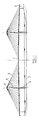
- Figure 1 est une vue en élévation d'un pont haubané auquel peut être adapté le dispositif selon la présente invention.
- Figure 2 est une coupe longitudinale d'une première réalisation d'un dispositif conforme à l'invention.
- Figure 3 est une coupe du dispositif de la figure 2 par un plan perpendiculaire au hauban.
- Figure 4 est une vue, dans une direction longitudinale, du dispositif de la figure 2.
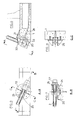
- Figure 5 est une vue, dans une direction transversale, d'une seconde réalisation de dispositif d'accrochage conforme à l'invention.
- Figure 6 est une coupe transversale partielle d'un tablier comportant le dispositif de la figure 5.
- Figure 7 est une coupe longitudinale du dispositif dans un plan incliné contenant le hauban.
- Figure 8 est une coupe du dispositif perpendiculaire à la direction du hauban.
- Figure 1 is an elevational view of a cable-stayed bridge to which the device according to the present invention can be adapted.
- Figure 2 is a longitudinal section of a first embodiment of a device according to the invention.
- Figure 3 is a section of the device of Figure 2 by a plane perpendicular to the stay.
- Figure 4 is a view, in a longitudinal direction, of the device of Figure 2.
- Figure 5 is a view, in a transverse direction, of a second embodiment of the attachment device according to the invention.
- Figure 6 is a partial cross section of an apron comprising the device of Figure 5.
- Figure 7 is a longitudinal section of the device in an inclined plane containing the shroud.
- Figure 8 is a section of the device perpendicular to the direction of the stay.
La figure 1 montre un pont, dont le tablier 1 repose à une extrémité sur des culées 2, et est soutenu par des haubans 3, qui relient des points successifs du tablier avec le sommet 4 de pylône 5 monté sur des piles 6, qui reposent sur le sol 7.Figure 1 shows a bridge, whose deck 1 rests at one end on
A la figure 2, on voit un dispositif d'accrochage selon l'invention monté sur la face supérieure, horizontale, d'un tablier 1.In FIG. 2, a hooking device according to the invention is seen mounted on the upper, horizontal face of an apron 1.
Le dispositif comprend une plaque 10, qui porte à sa partie inférieure un saillant tronconique 11, qui pénètre dans une cavité correspondante de la face supérieure du tablier 1. Sur la face supérieure de la plaque 10, des fers 12, 13, à section en T, sont fixés obliquement sur ladite plaque 11, leur direction générale faisant avec l'horizontale un angle égal à celui du hauban 3 que le dispositif est destiné à retenir. Une pièce d'accrochage 14, soudée aux fers 12 et 13, est traversée par l'extrémité du hauban 3, qui prend appui sur cette pièce 14 par l'intermédiaire d'une pièce terminale 15. Des tirants de précontrainte 16 traversent toute l'épaisseur du tablier 11, et, grâce à des vis 17, 18, serrent fortement la plaque 10 contre le tablier. Les efforts de traction exercés par le hauban 3 peuvent se décomposer en une composante verticale, qui est reprise par les tirants 16, et une composante horizontale, qui est transmise au tablier par le saillant 11 et par le frottement de la plaque 10 contre la surface horizontale d'appui prévue sur le tablier.The device comprises a
Les figures 5 à 8 montrent une autre forme de réalisation. Le tablier présente, sur son bord extérieur, ou rive, une surface d'appui 20, orientée longitudinalement, et un peu oblique par rapport à la verticale. La surface d'appui 20 est, dans l'ensemble, circulaire. Le tablier 1 étant relativement mince, il présente une surépaisseur 21 pour recevoir cette surface d'appui. Le dispositif d'accrochage proprement dit comprend une plaque 22, de forme circulaire, qui vient en appui sur la surface 20, et porte à sa partie tournée vers le tablier, une saillie tronconique 23 qui est creuse et vient se loger dans une cavité également tronconique 24 prévu au centre de la surface d'appui 20. Sur sa face opposée à la saillie 23, la plaque 22 porte des ferrures constituées de deux fers plats 25, identiques, disposées perpendiculairement à la plaque 20, et formant entre-elles une sorte de chape, entre lesquels vient se loger une pièce de support 26, contre laquelle porte une pièce d'extrémité 27 solidaire du hauban 3. La saillie creuse 23 sert de logement à la tête d'ancrage d'un câble de précontrainte 28, qui pénètre à l'intérieur du tablier 1 par un passage oblique, perpendiculaire au plan de la surface 20. Ce câble s'incurve ensuite pour devenir horizontal et traverse toute la largeur du tablier, pour venir s'ancrer sur un dispositif analogue situé sur la rive opposée du tablier.Figures 5 to 8 show another embodiment. The deck has, on its outer edge, or shore, a
On conçoit que, pour mettre en place les haubans, il faut orienter le dispositif par pivotement de la plaque autour de l'axe de la cavité 24, jusqu'à l'amener dans la bonne direction. L'inclinaison des surfaces 20 par rapport à l'horizontale est celle de tous les haubans de la même nappe de câbles qui soutiennent le bord du tablier. Il suffit, par conséquent, lors de la construction du pont, de prévoir sur le tablier des surfaces d'appui 20 identiques les unes aux autres, aux emplacements prévus, et d'orienter à chaque fois la plaque 22 pour obtenir un alignement parfait du dispositif d'accrochage avec les câbles.It is understood that, to set up the shrouds, the device must be oriented by pivoting the plate around the axis of the
Avec la disposition des figures 2 à 4, il est nécessaire de prévoir que l'orientation des ferrures 12 et 13 est modifiée pour chaque point d'accrochage. Cette complication est compensée par le fait qu'il n'est pas nécessaire d'avoir un câble de précontrainte traversant tout le tablier. Il est d'ailleurs possible de prévoir entre les ferrures 12 et 13 et la pièce d'accrochage 14, une liaison articulée, ce qui permet à ce moment là, au moins dans certaines limites, d'utiliser la même pièce pour un certain nombre de haubans.With the arrangement of Figures 2 to 4, it is necessary to provide that the orientation of the
Claims (8)
- une plaque métallique (10, 22), dont une face est conçue pour venir en appui contre une surface plane d'appui (20) du tablier (1), cette face portant au moins un saillant (11, 23) apte à pénétrer dans une cavité (24) du tablier pour empêcher un glissement relatif de la plaque et de ladite surface plane d'appui,
- des moyens d'accrochage (14, 15; 26, 27) de l'extrémité du hauban (3), ces moyens étant portés par des ferrures (12, 13; 25), solidaires de la face de la plaque opposée à celle qui est conçue pour venir en appui contre le tablier, et des câbles ou tirants de précontrainte, (16, 28), aptes à maintenir la plaque (10, 22) en appui contre la surface plane du tablier, ces câbles ou tirants prenant appui sur le côté du tablier (1) opposé à celui qui porte ladite surface plane.1. Device for attaching a stay cable (3) to a concrete deck (1) of a bridge, characterized in that it comprises:
- a metal plate (10, 22), one face of which is designed to come into abutment against a flat bearing surface (20) of the deck (1), this face carrying at least one projection (11, 23) capable of penetrating in a cavity (24) of the apron to prevent relative sliding of the plate and said flat bearing surface,
- hooking means (14, 15; 26, 27) of the end of the stay (3), these means being carried by fittings (12, 13; 25), integral with the face of the plate opposite to that which is designed to bear against the bulkhead, and prestressing cables or tie rods, (16, 28), capable of holding the plate (10, 22) bearing against the flat surface of the bulkhead, these cables or tie rods taking support on the side of the apron (1) opposite to that which carries said flat surface.
Priority Applications (1)
| Application Number | Priority Date | Filing Date | Title |
|---|---|---|---|
| AT89400311T ATE73186T1 (en) | 1988-02-05 | 1989-02-03 | DEVICES FOR CONNECTING A STAY CABLE TO A CONCRETE BRIDGE FLOOR AND BRIDGE EQUIPPED WITH THEM. |
Applications Claiming Priority (2)
| Application Number | Priority Date | Filing Date | Title |
|---|---|---|---|
| FR8801343 | 1988-02-05 | ||
| FR8801343A FR2626910B1 (en) | 1988-02-05 | 1988-02-05 | DEVICE FOR HANGING A STAY ON A CONCRETE APRON OF A BRIDGE, AND BRIDGE EQUIPPED WITH SUCH DEVICES |
Publications (2)
| Publication Number | Publication Date |
|---|---|
| EP0329516A1 true EP0329516A1 (en) | 1989-08-23 |
| EP0329516B1 EP0329516B1 (en) | 1992-03-04 |
Family
ID=9362967
Family Applications (1)
| Application Number | Title | Priority Date | Filing Date |
|---|---|---|---|
| EP89400311A Expired - Lifetime EP0329516B1 (en) | 1988-02-05 | 1989-02-03 | Device for securing a stay to a concrete bridge deck, and bridge featuring this |
Country Status (9)
| Country | Link |
|---|---|
| US (1) | US5088142A (en) |
| EP (1) | EP0329516B1 (en) |
| JP (1) | JPH02503100A (en) |
| AT (1) | ATE73186T1 (en) |
| DE (1) | DE68900887D1 (en) |
| ES (1) | ES2030278T3 (en) |
| FR (1) | FR2626910B1 (en) |
| GR (1) | GR3003968T3 (en) |
| WO (1) | WO1989007174A1 (en) |
Families Citing this family (3)
| Publication number | Priority date | Publication date | Assignee | Title |
|---|---|---|---|---|
| US7101928B1 (en) * | 1999-09-17 | 2006-09-05 | Landec Corporation | Polymeric thickeners for oil-containing compositions |
| KR20030000063A (en) * | 2001-06-22 | 2003-01-06 | 대림산업 주식회사 | Attachable anchorage block with developed shear friction and attaching method |
| CN104264584B (en) * | 2014-10-14 | 2017-01-18 | 中铁二院工程集团有限责任公司 | Combined cable-girder anchoring structure of pre-stressed concrete cable-stayed bridge top |
Citations (2)
| Publication number | Priority date | Publication date | Assignee | Title |
|---|---|---|---|---|
| US3953980A (en) * | 1975-01-13 | 1976-05-04 | Floyd William Bennett | Dock structure |
| EP0288350A1 (en) * | 1987-03-27 | 1988-10-26 | Societe Centrale D'etudes Et De Realisations Routieres- Scetauroute | Bridge consisting of a deck and its supporting means, especially a large-span cable-stayed bridge, and its construction process |
Family Cites Families (6)
| Publication number | Priority date | Publication date | Assignee | Title |
|---|---|---|---|---|
| US3414924A (en) * | 1966-11-21 | 1968-12-10 | Bethlehem Steel Corp | Bridge suspender collar |
| US3491393A (en) * | 1967-10-18 | 1970-01-27 | Bethlehem Steel Corp | Suspension bridge cable construction and support assembly |
| DE3434620A1 (en) * | 1984-09-21 | 1986-04-03 | Dyckerhoff & Widmann AG, 8000 München | SUPPORT OF A FREE TENSION LINK, PREFERABLY A CABLE ROPE OF A CABLE BRIDGE |
| FR2592666B1 (en) * | 1986-01-07 | 1988-03-11 | Sogelerg | SUPPORT SYSTEM BY FLEXIBLE CABLE WITH LOCAL BUILT-IN, ESPECIALLY FOR BRIDGE BRIDGES |
| FR2629111B1 (en) * | 1988-03-25 | 1990-11-30 | Muller Jean | APRON FOR LARGE LENGTH BRIDGE |
| FR2632805B1 (en) * | 1988-06-08 | 1990-08-24 | Bull Sa | EQUIPPED PRINTED CIRCUIT BOARD MASKING PLATE AND MANUFACTURING METHOD THEREOF |
-
1988
- 1988-02-05 FR FR8801343A patent/FR2626910B1/en not_active Expired - Lifetime
-
1989
- 1989-02-03 AT AT89400311T patent/ATE73186T1/en active
- 1989-02-03 EP EP89400311A patent/EP0329516B1/en not_active Expired - Lifetime
- 1989-02-03 JP JP1502103A patent/JPH02503100A/en active Pending
- 1989-02-03 US US07/425,201 patent/US5088142A/en not_active Expired - Fee Related
- 1989-02-03 WO PCT/FR1989/000041 patent/WO1989007174A1/en unknown
- 1989-02-03 ES ES198989400311T patent/ES2030278T3/en not_active Expired - Lifetime
- 1989-02-03 DE DE8989400311T patent/DE68900887D1/en not_active Expired - Fee Related
-
1992
- 1992-03-05 GR GR910401865T patent/GR3003968T3/el unknown
Patent Citations (2)
| Publication number | Priority date | Publication date | Assignee | Title |
|---|---|---|---|---|
| US3953980A (en) * | 1975-01-13 | 1976-05-04 | Floyd William Bennett | Dock structure |
| EP0288350A1 (en) * | 1987-03-27 | 1988-10-26 | Societe Centrale D'etudes Et De Realisations Routieres- Scetauroute | Bridge consisting of a deck and its supporting means, especially a large-span cable-stayed bridge, and its construction process |
Also Published As
| Publication number | Publication date |
|---|---|
| GR3003968T3 (en) | 1993-03-16 |
| FR2626910B1 (en) | 1990-06-29 |
| DE68900887D1 (en) | 1992-04-09 |
| JPH02503100A (en) | 1990-09-27 |
| ATE73186T1 (en) | 1992-03-15 |
| ES2030278T3 (en) | 1992-10-16 |
| EP0329516B1 (en) | 1992-03-04 |
| WO1989007174A1 (en) | 1989-08-10 |
| US5088142A (en) | 1992-02-18 |
| FR2626910A1 (en) | 1989-08-11 |
Similar Documents
| Publication | Publication Date | Title |
|---|---|---|
| EP0802145B1 (en) | Hoisting yoke | |
| EP0083289B1 (en) | Rotor wheel of a turbo jet engine comprising a device for axially and radially retaining the rotor blades on the rotor wheel | |
| FR2757602A1 (en) | CABLE SEAT AND CABLE LAYING METHOD | |
| FR2987853A1 (en) | CALIPER FOR FIXING A GUARD RAIL ON AN AMOUNT | |
| EP0329516B1 (en) | Device for securing a stay to a concrete bridge deck, and bridge featuring this | |
| FR2723876A1 (en) | DEVICE FOR CUTTING BELT | |
| FR2860013A1 (en) | Bridge for crossing e.g. river, has support structure with lifting unit that is arranged on one side of channel and has traction ropes whose one end is fixed to bay and another end is fixed to traction device | |
| FR2620468A1 (en) | DECK HEAD FOR THE CROSS CROSSING OF A PIT | |
| EP1010843B1 (en) | Device forming foot-support for stake or post, in particular for arbour or panel support and method for its closing | |
| FR2744786A1 (en) | Girder assembly for bridge or pylon | |
| EP0282416B1 (en) | Cutting machine with a cutter head movebly mounted on an arched guide oblique to its axis | |
| FR2772411A1 (en) | Protective system for falling objects | |
| EP1010840A1 (en) | Device forming foot-support for stake or post, in particular for arbour or panel support and method for its closing | |
| FR2665920A1 (en) | Prefabricated stairway made of concrete for a basement | |
| EP0433170A1 (en) | Bridge with piers bearing successive bridge-deck elements | |
| EP1647648B1 (en) | Connecting device between a corner post and two filler panels for a railing | |
| FR2806429A1 (en) | METHOD FOR REINFORCING A CARRIER CABLE WITH A SUSPENDED CIVIL ENGINEERING STRUCTURE AND CIVIL ENGINEERING STRUCTURE COMPRISING A REINFORCED CARRIER CABLE | |
| FR2778213A1 (en) | ASSEMBLY FOR REALIZING A FLANGE, FLANGE COMPRISING THIS ASSEMBLY AND CONSTRUCTION COMPRISING A MAT ASSOCIATED WITH AT LEAST ONE HAMPER BY THIS FLANGE | |
| FR2892138A1 (en) | Above-ground swimming pool of polygonal shape has timber beam walls and reinforcing uprights with lower ends of opposite uprights joined by thin connectors | |
| FR2728002A1 (en) | Guard rail structure esp. for resisting lateral forces | |
| EP3985190A1 (en) | Fastening device for a post | |
| FR2797427A1 (en) | Articulated gangway between quay and moored vessel has fixed rail on quay for sliding platform linked to swivelling platform on gangway end | |
| FR2731031A1 (en) | Method of installing handrail used e.g. for escalator, or stadium stairs | |
| FR2866360A1 (en) | Anchor for fixing stringer to ground, has two plates with shapes that cooperate with each other to ensure their connection, and rod having end that is connected to slit of one plate | |
| FR2523403A1 (en) | Convex octagonal trawl board - receives warp and arm of intrados and extrados respectively and is symmetrical w.r.t. vertical and transverse axes |
Legal Events
| Date | Code | Title | Description |
|---|---|---|---|
| PUAI | Public reference made under article 153(3) epc to a published international application that has entered the european phase |
Free format text: ORIGINAL CODE: 0009012 |
|
| AK | Designated contracting states |
Kind code of ref document: A1 Designated state(s): AT BE CH DE ES FR GB GR IT LI LU NL SE |
|
| 17P | Request for examination filed |
Effective date: 19900201 |
|
| 17Q | First examination report despatched |
Effective date: 19910708 |
|
| DIN1 | Information on inventor provided before grant (deleted) | ||
| RAP1 | Party data changed (applicant data changed or rights of an application transferred) |
Owner name: SOCIETE CENTRALE D'ETUDES ET DE REALISATIONS ROUTI |
|
| RIN1 | Information on inventor provided before grant (corrected) |
Inventor name: MULLER, JEAN |
|
| GRAA | (expected) grant |
Free format text: ORIGINAL CODE: 0009210 |
|
| AK | Designated contracting states |
Kind code of ref document: B1 Designated state(s): AT BE CH DE ES FR GB GR IT LI LU NL SE |
|
| PG25 | Lapsed in a contracting state [announced via postgrant information from national office to epo] |
Ref country code: NL Effective date: 19920304 Ref country code: AT Effective date: 19920304 |
|
| REF | Corresponds to: |
Ref document number: 73186 Country of ref document: AT Date of ref document: 19920315 Kind code of ref document: T |
|
| GBT | Gb: translation of ep patent filed (gb section 77(6)(a)/1977) | ||
| REF | Corresponds to: |
Ref document number: 68900887 Country of ref document: DE Date of ref document: 19920409 |
|
| ITF | It: translation for a ep patent filed |
Owner name: STUDIO CONS. BREVETTUALE S.R.L. |
|
| NLV1 | Nl: lapsed or annulled due to failure to fulfill the requirements of art. 29p and 29m of the patents act | ||
| REG | Reference to a national code |
Ref country code: ES Ref legal event code: FG2A Ref document number: 2030278 Country of ref document: ES Kind code of ref document: T3 |
|
| REG | Reference to a national code |
Ref country code: GR Ref legal event code: FG4A Free format text: 3003968 |
|
| PLBE | No opposition filed within time limit |
Free format text: ORIGINAL CODE: 0009261 |
|
| STAA | Information on the status of an ep patent application or granted ep patent |
Free format text: STATUS: NO OPPOSITION FILED WITHIN TIME LIMIT |
|
| 26N | No opposition filed | ||
| PGFP | Annual fee paid to national office [announced via postgrant information from national office to epo] |
Ref country code: GR Payment date: 19931231 Year of fee payment: 6 |
|
| PGFP | Annual fee paid to national office [announced via postgrant information from national office to epo] |
Ref country code: LU Payment date: 19940228 Year of fee payment: 6 |
|
| EPTA | Lu: last paid annual fee | ||
| PGFP | Annual fee paid to national office [announced via postgrant information from national office to epo] |
Ref country code: FR Payment date: 19950123 Year of fee payment: 7 |
|
| PGFP | Annual fee paid to national office [announced via postgrant information from national office to epo] |
Ref country code: GB Payment date: 19950127 Year of fee payment: 7 |
|
| EAL | Se: european patent in force in sweden |
Ref document number: 89400311.0 |
|
| PG25 | Lapsed in a contracting state [announced via postgrant information from national office to epo] |
Ref country code: LU Free format text: LAPSE BECAUSE OF NON-PAYMENT OF DUE FEES Effective date: 19950203 |
|
| PGFP | Annual fee paid to national office [announced via postgrant information from national office to epo] |
Ref country code: DE Payment date: 19950210 Year of fee payment: 7 |
|
| PGFP | Annual fee paid to national office [announced via postgrant information from national office to epo] |
Ref country code: ES Payment date: 19950216 Year of fee payment: 7 |
|
| PGFP | Annual fee paid to national office [announced via postgrant information from national office to epo] |
Ref country code: SE Payment date: 19950220 Year of fee payment: 7 |
|
| PGFP | Annual fee paid to national office [announced via postgrant information from national office to epo] |
Ref country code: CH Payment date: 19950223 Year of fee payment: 7 |
|
| PGFP | Annual fee paid to national office [announced via postgrant information from national office to epo] |
Ref country code: BE Payment date: 19950306 Year of fee payment: 7 |
|
| PG25 | Lapsed in a contracting state [announced via postgrant information from national office to epo] |
Ref country code: GR Free format text: THE PATENT HAS BEEN ANNULLED BY A DECISION OF A NATIONAL AUTHORITY Effective date: 19950831 |
|
| REG | Reference to a national code |
Ref country code: GR Ref legal event code: MM2A Free format text: 3003968 |
|
| PG25 | Lapsed in a contracting state [announced via postgrant information from national office to epo] |
Ref country code: GB Effective date: 19960203 |
|
| PG25 | Lapsed in a contracting state [announced via postgrant information from national office to epo] |
Ref country code: SE Effective date: 19960204 |
|
| PG25 | Lapsed in a contracting state [announced via postgrant information from national office to epo] |
Ref country code: ES Free format text: LAPSE BECAUSE OF NON-PAYMENT OF DUE FEES Effective date: 19960205 |
|
| PG25 | Lapsed in a contracting state [announced via postgrant information from national office to epo] |
Ref country code: LI Free format text: LAPSE BECAUSE OF NON-PAYMENT OF DUE FEES Effective date: 19960228 Ref country code: CH Free format text: LAPSE BECAUSE OF NON-PAYMENT OF DUE FEES Effective date: 19960228 Ref country code: BE Effective date: 19960228 |
|
| BERE | Be: lapsed |
Owner name: SOC. CENTRALE D'ETUDES ET DE REALISATIONS ROUTIERE Effective date: 19960228 |
|
| GBPC | Gb: european patent ceased through non-payment of renewal fee |
Effective date: 19960203 |
|
| REG | Reference to a national code |
Ref country code: CH Ref legal event code: PL |
|
| PG25 | Lapsed in a contracting state [announced via postgrant information from national office to epo] |
Ref country code: FR Effective date: 19961031 |
|
| PG25 | Lapsed in a contracting state [announced via postgrant information from national office to epo] |
Ref country code: DE Effective date: 19961101 |
|
| REG | Reference to a national code |
Ref country code: FR Ref legal event code: ST |
|
| REG | Reference to a national code |
Ref country code: ES Ref legal event code: FD2A Effective date: 19990503 |
|
| PG25 | Lapsed in a contracting state [announced via postgrant information from national office to epo] |
Ref country code: IT Free format text: LAPSE BECAUSE OF NON-PAYMENT OF DUE FEES Effective date: 20050203 |