EP0329284B1 - Forming and filling flexible plastic packaging, packaging, and assembling and packaging, articles, and transferring groups of products - Google Patents
Forming and filling flexible plastic packaging, packaging, and assembling and packaging, articles, and transferring groups of products Download PDFInfo
- Publication number
- EP0329284B1 EP0329284B1 EP89300575A EP89300575A EP0329284B1 EP 0329284 B1 EP0329284 B1 EP 0329284B1 EP 89300575 A EP89300575 A EP 89300575A EP 89300575 A EP89300575 A EP 89300575A EP 0329284 B1 EP0329284 B1 EP 0329284B1
- Authority
- EP
- European Patent Office
- Prior art keywords
- articles
- further characterised
- transfer mechanism
- operatively
- groups
- Prior art date
- Legal status (The legal status is an assumption and is not a legal conclusion. Google has not performed a legal analysis and makes no representation as to the accuracy of the status listed.)
- Expired - Lifetime
Links
Images

Classifications
-
- B—PERFORMING OPERATIONS; TRANSPORTING
- B65—CONVEYING; PACKING; STORING; HANDLING THIN OR FILAMENTARY MATERIAL
- B65B—MACHINES, APPARATUS OR DEVICES FOR, OR METHODS OF, PACKAGING ARTICLES OR MATERIALS; UNPACKING
- B65B9/00—Enclosing successive articles, or quantities of material, e.g. liquids or semiliquids, in flat, folded, or tubular webs of flexible sheet material; Subdividing filled flexible tubes to form packages
- B65B9/02—Enclosing successive articles, or quantities of material between opposed webs
- B65B9/04—Enclosing successive articles, or quantities of material between opposed webs one or both webs being formed with pockets for the reception of the articles, or of the quantities of material
-
- B—PERFORMING OPERATIONS; TRANSPORTING
- B65—CONVEYING; PACKING; STORING; HANDLING THIN OR FILAMENTARY MATERIAL
- B65B—MACHINES, APPARATUS OR DEVICES FOR, OR METHODS OF, PACKAGING ARTICLES OR MATERIALS; UNPACKING
- B65B47/00—Apparatus or devices for forming pockets or receptacles in or from sheets, blanks, or webs, comprising essentially a die into which the material is pressed or a folding die through which the material is moved
- B65B47/08—Apparatus or devices for forming pockets or receptacles in or from sheets, blanks, or webs, comprising essentially a die into which the material is pressed or a folding die through which the material is moved by application of fluid pressure
Definitions
- the invention relates to forming and filling flexible plastic packaging, and assembling and packaging, articles, and to simultaneously transferring groups of products.
- a web of plastic is advanced through a vacuum thermoformer (where the plastic web is formed to provide receptacles for receiving articles), a filling station (where articles are placed in the formed receptacles), a sealer (where a second sheet is placed over the filled receptacles and sealed to portions of the web around the receptacles to provide covers), and a cutter (where the plastic web is cut at portions between receptacles into separate packages).
- thermoforming in which a vacuum in a female mold draws heated film into the desired shape against the female mold, with or without assistance from positive pressure on the other side of the plastic
- positive male forming in which a vaccum in a male mold and positive pressure applied on the other side of the plastic draw the heated film into the desired shape against the male mold
- male plug-assisted negative forming in which a vacuum in a female mold and a mechanical male plug on the opposite side of film are used, with or without an optional sandwich heater.
- Such apparatus has been used to form both rigid and flexible receptacles, the former in general having walls that are 8 to 50 mils in thickness (depending on the plastic and application) and maintain their shape, the latter in general having walls that are less than 8 mils in thickness and readily flex and change shape.
- the differences in size and properties of rigid vis-a-vis flexible walls result in differences in the responses of the plastics to heat and force and in the types of thermoforming procedures employed.
- Flexible film thermoforming conventionally involves simple application of vacuum to easily draw the heated plastic to the mold; there often is, however, substantial stretching of the plastic, resulting in uneven reduction in wall thickness.
- Rigid wall thermoforming may very well involve procedures employing assistance from positive pressure in addition to vacuum and has also involved a two-step procedure of first providing a light vacuum to provide initial contour and thereafter providing both vacuum and pressure to force the film into the shape of the mold.
- Apparatus for providing packaged articles including a form-and-fill packaging line is known from FR-A-2 248 130.
- This document discloses a hopper from which articles are randomly discharged into flexible tubes. The articles pass down these tubes under gravity, and drop into holes in a roller. Rotation of the roller drops a row of articles into a corresponding row of receptacles. Articles from a portion of two rows of receptacles with articles are then packaged as a group.
- a form-and-fill packaging line including a vacuum thermoformer where a plastic web is formed to provide receptacles for receiving said articles, a filling station in which articles are placed in respective receptacles in said web, a transporting line being provided along which articles are arranged to pass in serial order to said filling station, and a sealer where a sheet seals closed the filled receptacles;
- said apparatus including an assembler section in which respective said articles are adapted individually to be assembled from parts thereof and from which articles so assembled are arranged to be serially discharged one-after-the-other to said transporting line, and a transfer mechanism located at said filling station, said transfer mechanism being adapted to pick up at least one group of said articles transported by said transporting line to a first location at said filling station, said articles being arranged in the or each said group in the order in which they are received at said first location, and said transfer mechanism also being adapted to deposit said group(s) of articles at a
- the transporting line includes a gate for selectively removing articles from it and directing them to a hopper for temporary storage and a reentry mechanism for causing the articles in the hopper to reenter the transporting line.
- the transporting line includes a track on which the articles are maintained in a predetermined orientation as they move along the track.
- There is a conveyor belt at the end of the track for presenting the articles at the filling station.
- the conveyor belt carries the articles in two rows to the filling station, and there are two tracks for carrying the articles to the conveyor belt.
- the articles are syringes that have wings that are supported by spaced parallel horizontal track portions and have vertically oriented bodies between the track portions during transport.
- Means are provided for inspecting articles prior to transfer in groups to receptacles in order to identify defective products and selectively remove products so that only groups containing defect-free products are transferred. Defective articles removed from the conveyor are transferred to one bin and defect-free articles are transferred to another. The transfer mechanism waits while the conveyor incrementally moves articles to the first location for transfer to the packaging line until there is a complete group of defect-free articles. Means are provided for transferring a group of products on a conveyor to a receiving station, using a second transfer mechanism. At least one of the transfer mechanisms uses separately movable product engagers to change the relative positions of the products in the groups with respect to each other (by moving the relative positions of the product engagers) prior to dropping the products off at the receiving station.
- the product engagers are vacuum engagement members provided on the ends of longitudinally extendable cross-arms.
- the ends of the cross-arms are pneumatically actuated to an extended stop position and spring-returned to a retracted position.
- the cross-arms are supported on a robot that is capable of movement along three orthogonal axes.
- the said divisional application is concerned in one aspect with a method of forming and filling flexible plastic packages comprising forming a web of plastic pulled through and processed in a thermoformer to provide formed receptacles, placing articles in said formed receptacles to provide filled receptacles, providing a cover over said filled receptacles, sealing said cover to said web around said receptacles, and cutting said web between said filled receptacles to provide separate packages, characterised in that said forming comprises, advancing a thin flexible web of plastic through said thermoformer, providing a first pressure difference on opposite sides of said plastic web when heated and positioned in a mold of said thermoformer to provide an initial contour with substantially uniform stretching of said heated, plastic web, and thereafter providing a second pressure difference which is larger than said first pressure difference and is sufficiently large to force the heated plastic web into the desired shape of a mold of said thermoformer to provide formed receptacles with a wall thickness at least equal to a predetermined minimum thickness sufficient to maintain integrity
- thermoforming flexible plastic web in a thermoformer characterised in comprising advancing a thin flexible web of plastic through said thermoformer, providing a first pressure difference on opposite sides of said plastic web when heated and positioned in a mold of said thermoformer to provide an initial contour with substantially uniform stretching of said heated, plastic web and thereafter providing a second pressure difference which is larger than said first pressure difference and is sufficiently large to force the heated web into the desired shape of a mold of said thermoformer to provide a wall thickness at least equal to a predetermined minimum thickness sufficient to maintain integrity.
- Fig. 1 is a diagrammatic plan view of form-and-fill packaging apparatus and associated transporting line according to the invention.
- Fig. 2 is a diagrammatic elevation of a robot used in the Fig. 1 apparatus to transfer syringes from a supply belt to formed receptacles.
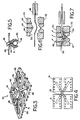
- Fig. 3 is a diagrammatic perspective view of an article pickup mechanism of the Fig. 1 apparatus.
- Fig. 4 is a diagrammatic bottom plan view of the Fig. 3 pickup mechanism.
- Fig. 5 is a diagrammatic vertical sectional view of an engagement foot of the Fig. 3 mechanism shown engaging a syringe.
- Fig. 6 is a diagrammatic vertical sectional view of a heater and portions of multiple-receptacle molds of a thermoformer of the Fig. 1 apparatus in position during an initial step of a forming operation.
- Fig. 7 is a diagrammatic vertical sectional view of a heater and portions of multiple-receptacle molds of the Fig. 1 apparatus in a later step of the forming operation.
- FIG. 1 there is shown form and fill packaging apparatus 10 used in conjunction with syringe assembler 11 and transporting line 13, for transporting assembled syringes 18 for packaging at apparatus 10.
- Form and fill apparatus 10 includes vacuum thermoformer 12, for forming web of plastic 14 advanced from supply roll 15 through it so as to provide formed receptacles 16 for receiving syringes 18 at downstream filling station 19.
- Seal and cover unit 20 is positioned to provide a cover over filled receptacles 16, and cutter 22 is positioned to cut the formed, filled, and sealed web into individual packaged products 24 containing five syringes 18 each.
- Transporting line 13 includes in-line tracks 25, 27 on which syringes 18 are transported with their wings extending outward over spaced horizontal portions of tracks 25, 27, the syringe bodies being vertically oriented in the space between the two portions of the tracks. Orienting rolls 61 capture syringes 18 in horizontal orientation and introduce them vertically into track 25. Diverter 23 splits the syringes coming from syringe assembler 11 on track 25 into two streams, one along the continuation of track 25 and one along track 27. Downstream of diverter 23 on tracks 25, 27 are chute gates 29 for selectively discharging syringes into hoppers 31.
- Each hopper 31 has an associated elevator 51, rotary disk bowl feeder 35, and orientation rolls 37 (to place syringes in vertical orientation) for returning syringes in hoppers 31 to their respective tracks 25, 27 as desired.
- Syringes are moved along tracks 25, 27 by upstream star wheel conveyors 39 and downstream star wheel conveyors 41.
- Track 25 has a one-half C end-section to discharge chute 43 to reorient syringes 18 to a horizontal position and deliver syringes 18 horizontally to the left-hand belt of infeed conveyor belt 26.
- Track 27 similarly has a one-half C end-section and associated chute 45 for delivering syringes in a horizontal manner to the right-hand belt of infeed conveyor belt 26.
- Each belt of conveyor belt 26 has troughs 28 that are appropriately spaced for pick up by robot 30 (an Adept robot) and discharge into receptacles 16.
- Visual inspection monitor 45 is along belt 26.
- two-compartment bin 49 having one compartment for good syringes and one for defective syringes and a mechanism (not shown) for selectively directing good and defective syringes to their respective compartments.
- Robot 30 and multiple pickup member 32 of loading station 19 are positioned near the junction of infeed belt 26 and the web of formed receptacles 16, to load syringes 18 from belt 26 into receptacles 16.
- Conveyor 47 and robot 45 are adjacent to the end of belt 29, carrying packaged products 24 from cutter 22.
- robot 30 includes rotatable main shaft 33, primary arm 34 connected to it, secondary arm 36 rotatably connected to arm 34, and shaft 38.
- Shaft 38 is mounted for vertical movement on arm 36 and carries, on its lower end, bracket 40, for mounting to pickup member 32.
- pickup member 32 includes flange 34, for attaching to bracket 40, and cross arms 36 secured at respective ends to four pads 88, each of which has ten rubber feet 41 in position to engage syringes 18.
- each foot 41 has a U-shaped recess 42 and vacuum passage 44, leading to recess 42 and connected to vacuum tubes 46.
- Robot 45 carries a multiple pickup member and rotatable arms (not shown) that is similar to member 32, except that its feet are shaped like suction cups, and its cross arms are longitudinally extendable.
- Molds 50, 52 include passages 54 for selectively providing vacuum or positive pressure to region 56 between them.
- web 14 is advanced from roll 15, heated at heater 48 (Figs. 6 and 7) to, e.g., about 80°C to 90°C, and thereafter advanced to position between male and female molds 50, 52. Heated web 14 is subjected to a light vacuum applied at female mold 52, causing a difference in pressure on opposite sides of web 14 that urges web 14 to begin assuming the shape of female mold 52 with uniform stretching (Fig. 6). Thereafter vacuum is applies at male mold 50 and positive pressure is applied at female mold 52 (Fig. 7), causing a larger difference in pressure (and in the opposite direction) and web 14 to move into contact with water-cooled (e.g., about 65°F) male mold 50 continuously along its surface.
- water-cooled e.g., about 65°F
- the two-step procedure has about a 3-5 second cycle, with about 1/4 to 1/2 second in the first step, depending on the plastic and thickness.
- the two-step procedure greatly reduces stretching and the resulting weakened material and provides more uniform wall thickness in the resulting formed receptacle. Thinner, less expensive stock can thus be used while maintaining desired, minimum thicknesses.
- web 14 is advanced to move a fresh portion of the web into thermoformer 12 and to move twenty formed receptacles 16 into position at filling station 19 for simultaneous filling with a group of twenty syringes 18.
- Syringes 18 are assembled at syringe assembler 11 and discharged to orienting rolls 61 one-at-a-time in horizontal orientation as they are assembled. Syringes 18 are vertically oriented at rolls 61 and received on track 25, where the syringes maintain the vertical orientation with the wings extending over spaced horizontal members of track 25. Star wheel mechanism 39 pushes syringes between its two wheels along track 25. At diverter 23 some of the syringes are diverted to track 27. The syringes continue along tracks 25, 27 and are delivered at chutes 43, 45 in horizontal orientation to the left- and right-hand rows of troughs 28, receiving an additional push at star wheels 41, 43.
- syringes 18 can be discharged and temporarily stored into hopper 31 and later incorporated back into the feed to infeed belt 26 at a time when form and fill line 10 is operating faster than assembler 11 or at a time when assembler 11 is not operating.
- the discharge of syringes into hopper 31 is controlled by chute gates 29.
- syringes When the syringes reenter tracks 25,27, they are raised by elevator 30 to rotary disk bowl feeder 35, which feeds the syringes 18 to orienting rolls 37 at which the syringes are placed in their vertical orientation with the wings on opposite sides of an opening between horizontal track members. Hoppers 31 can also be manually loaded with previously assembled syringes in the event of failure of syringe assembler 11.
- Syringes delivered to troughs 28 of infeed belt 26 are advanced toward form and fill line apparatus 10 and are scanned by inspection station 45 to determine if there are any defective syringes (for example, whether the spacing between the wings and the plunger is within specifications, and whether all parts are present).
- the left- and right-hand belts of conveyor belt 26 operate synchronously when defective parts are not detected. Twenty syringes 18 are transferred at a time by robot 30 in four groups of five.
- inspection station 45 If inspection station 45 identifies a faulty syringe, it is dropped into bin 47 along with any other syringes that would prevent transfer of a group of twenty defect-free syringes; for example, if the defective syringe was the fourth one from the front on the right-hand side of a group of twenty to be transferred, then the right-hand belt advances four increments, discharging the defective fourth syringe and the three syringes before it on the right-hand belt into the bin.
- the gate in bin 47 directs the first three defect-free syringes to one compartment and the defective fourth syringe to another.
- pickup member 32 In making the transfer of syringes 18 from belt 26 to receptacles 16, pickup member 32 is lowered into position over infeed belt 26 by vertical movement of shaft 38, and a vacuum applied to feet 41 causes engagement of syringes 18, two feet 41 engaging each syringe 18. Pickup member 32 is then raised by movement of shaft 38 and moved into the position shown in Fig. 1 by relative rotation of arms 34, 36 and rotation of primary shaft 33. Pickup member 32 is then lowered, and the vacuums are disengaged, permitting syringes 18 to fall into their respective receptacles 16. In travel of syringes 18 from assembler 11 to receptacles 16, syringes 18 maintain predetermined orientations during travel and are captured at all times.
- the filled receptacles 16 are moved to seal and cover unit 20, where a cover sheet is sealed to the portions of web 14 between and around the receptacles.
- the loaded, covered, and sealed receptacles are then vertically and horizontally cut at cutter 22 to provide individual packaged products 24 of five syringes each.
- Robot 45 (similar to robot 30) transfers sealed packaged products 24, four at a time, to four boxes 58 on conveyor 47, alternating the orientation of each layer, and extending arms 36 before releasing packaged products 24 in boxes 58 to provide spacing for boxes 58.
- conveyor 47 moves a new set of four boxes 58 into position
- Packaged products 24 can be sterilized by electron beam, ethylene oxide, or radiation sterilization and reliably maintain their integrity and sterilization, owing to the wall thickness.
- conveyor 47 alternating the orientation of each layer, and extending arms 36 before releasing packaged products 24 in boxes 58 to provide spacing for boxes 58.
- conveyor 47 moves a new set of four boxes 58 into position.
- Packaged products 24 can be sterilized by electron beam, ethylene oxide, or radiation sterilization and reliably maintain their integrity of sterilization, owing to the wall thickness.
Description
- In its various aspects, the invention relates to forming and filling flexible plastic packaging, and assembling and packaging, articles, and to simultaneously transferring groups of products.
- In form and fill packaging apparatus, a web of plastic is advanced through a vacuum thermoformer (where the plastic web is formed to provide receptacles for receiving articles), a filling station (where articles are placed in the formed receptacles), a sealer (where a second sheet is placed over the filled receptacles and sealed to portions of the web around the receptacles to provide covers), and a cutter (where the plastic web is cut at portions between receptacles into separate packages).
- In such apparatus different thermoforming methods have been employed, e.g., negative forming (in which a vacuum in a female mold draws heated film into the desired shape against the female mold, with or without assistance from positive pressure on the other side of the plastic), positive male forming (in which a vaccum in a male mold and positive pressure applied on the other side of the plastic draw the heated film into the desired shape against the male mold), and male plug-assisted negative forming (in which a vacuum in a female mold and a mechanical male plug on the opposite side of film are used, with or without an optional sandwich heater).
- Such apparatus has been used to form both rigid and flexible receptacles, the former in general having walls that are 8 to 50 mils in thickness (depending on the plastic and application) and maintain their shape, the latter in general having walls that are less than 8 mils in thickness and readily flex and change shape. The differences in size and properties of rigid vis-a-vis flexible walls result in differences in the responses of the plastics to heat and force and in the types of thermoforming procedures employed. Flexible film thermoforming conventionally involves simple application of vacuum to easily draw the heated plastic to the mold; there often is, however, substantial stretching of the plastic, resulting in uneven reduction in wall thickness. Rigid wall thermoforming may very well involve procedures employing assistance from positive pressure in addition to vacuum and has also involved a two-step procedure of first providing a light vacuum to provide initial contour and thereafter providing both vacuum and pressure to force the film into the shape of the mold.
- Apparatus for providing packaged articles, including a form-and-fill packaging line is known from FR-A-2 248 130. This document discloses a hopper from which articles are randomly discharged into flexible tubes. The articles pass down these tubes under gravity, and drop into holes in a roller. Rotation of the roller drops a row of articles into a corresponding row of receptacles. Articles from a portion of two rows of receptacles with articles are then packaged as a group.
- We provide apparatus for providing articles packaged in groups, comprising a form-and-fill packaging line including a vacuum thermoformer where a plastic web is formed to provide receptacles for receiving said articles, a filling station in which articles are placed in respective receptacles in said web, a transporting line being provided along which articles are arranged to pass in serial order to said filling station, and a sealer where a sheet seals closed the filled receptacles; said apparatus including an assembler section in which respective said articles are adapted individually to be assembled from parts thereof and from which articles so assembled are arranged to be serially discharged one-after-the-other to said transporting line, and a transfer mechanism located at said filling station, said transfer mechanism being adapted to pick up at least one group of said articles transported by said transporting line to a first location at said filling station, said articles being arranged in the or each said group in the order in which they are received at said first location, and said transfer mechanism also being adapted to deposit said group(s) of articles at a second location in(a) correspondingly arranged group(s) of said receptacles in said web; said groups in which said articles are packaged corresponding to groups in rich said articles are picked up and deposited by said transfer mechanism.
- In preferred embodiments the transporting line includes a gate for selectively removing articles from it and directing them to a hopper for temporary storage and a reentry mechanism for causing the articles in the hopper to reenter the transporting line. The transporting line includes a track on which the articles are maintained in a predetermined orientation as they move along the track. There is a conveyor belt at the end of the track for presenting the articles at the filling station. The conveyor belt carries the articles in two rows to the filling station, and there are two tracks for carrying the articles to the conveyor belt. The articles are syringes that have wings that are supported by spaced parallel horizontal track portions and have vertically oriented bodies between the track portions during transport. Means are provided for inspecting articles prior to transfer in groups to receptacles in order to identify defective products and selectively remove products so that only groups containing defect-free products are transferred. Defective articles removed from the conveyor are transferred to one bin and defect-free articles are transferred to another. The transfer mechanism waits while the conveyor incrementally moves articles to the first location for transfer to the packaging line until there is a complete group of defect-free articles. Means are provided for transferring a group of products on a conveyor to a receiving station, using a second transfer mechanism. At least one of the transfer mechanisms uses separately movable product engagers to change the relative positions of the products in the groups with respect to each other (by moving the relative positions of the product engagers) prior to dropping the products off at the receiving station. The product engagers are vacuum engagement members provided on the ends of longitudinally extendable cross-arms. The ends of the cross-arms are pneumatically actuated to an extended stop position and spring-returned to a retracted position. The cross-arms are supported on a robot that is capable of movement along three orthogonal axes.
- Reference should also be made to the text of European Patent Application 91116173.5 (EP-A 0 464 876) which was divided out of the present application.
- The said divisional application is concerned in one aspect with a method of forming and filling flexible plastic packages comprising forming a web of plastic pulled through and processed in a thermoformer to provide formed receptacles, placing articles in said formed receptacles to provide filled receptacles, providing a cover over said filled receptacles, sealing said cover to said web around said receptacles, and cutting said web between said filled receptacles to provide separate packages, characterised in that said forming comprises, advancing a thin flexible web of plastic through said thermoformer, providing a first pressure difference on opposite sides of said plastic web when heated and positioned in a mold of said thermoformer to provide an initial contour with substantially uniform stretching of said heated, plastic web, and thereafter providing a second pressure difference which is larger than said first pressure difference and is sufficiently large to force the heated plastic web into the desired shape of a mold of said thermoformer to provide formed receptacles with a wall thickness at least equal to a predetermined minimum thickness sufficient to maintain integrity of said packages.
- In an alternative aspect, thereof, the aforesaid divisional application is concerned with a method of thermoforming flexible plastic web in a thermoformer characterised in comprising advancing a thin flexible web of plastic through said thermoformer, providing a first pressure difference on opposite sides of said plastic web when heated and positioned in a mold of said thermoformer to provide an initial contour with substantially uniform stretching of said heated, plastic web and thereafter providing a second pressure difference which is larger than said first pressure difference and is sufficiently large to force the heated web into the desired shape of a mold of said thermoformer to provide a wall thickness at least equal to a predetermined minimum thickness sufficient to maintain integrity.
- The invention is described below, by way of example only with reference to the accompanying drawings in which :
- Fig. 1 is a diagrammatic plan view of form-and-fill packaging apparatus and associated transporting line according to the invention.
- Fig. 2 is a diagrammatic elevation of a robot used in the Fig. 1 apparatus to transfer syringes from a supply belt to formed receptacles.
- Fig. 3 is a diagrammatic perspective view of an article pickup mechanism of the Fig. 1 apparatus.
- Fig. 4 is a diagrammatic bottom plan view of the Fig. 3 pickup mechanism.
- Fig. 5 is a diagrammatic vertical sectional view of an engagement foot of the Fig. 3 mechanism shown engaging a syringe.
- Fig. 6 is a diagrammatic vertical sectional view of a heater and portions of multiple-receptacle molds of a thermoformer of the Fig. 1 apparatus in position during an initial step of a forming operation.
- Fig. 7 is a diagrammatic vertical sectional view of a heater and portions of multiple-receptacle molds of the Fig. 1 apparatus in a later step of the forming operation.
- Referring to Fig. 1, there is shown form and fill packaging apparatus 10 used in conjunction with syringe assembler 11 and
transporting line 13, for transporting assembledsyringes 18 for packaging at apparatus 10. - Form and fill apparatus 10 includes
vacuum thermoformer 12, for forming web ofplastic 14 advanced fromsupply roll 15 through it so as to provide formedreceptacles 16 for receivingsyringes 18 atdownstream filling station 19. Seal andcover unit 20 is positioned to provide a cover over filledreceptacles 16, andcutter 22 is positioned to cut the formed, filled, and sealed web into individual packagedproducts 24 containing fivesyringes 18 each. -
Transporting line 13 includes in-line tracks syringes 18 are transported with their wings extending outward over spaced horizontal portions oftracks Orienting rolls 61 capturesyringes 18 in horizontal orientation and introduce them vertically intotrack 25.Diverter 23 splits the syringes coming from syringe assembler 11 ontrack 25 into two streams, one along the continuation oftrack 25 and one alongtrack 27. Downstream of diverter 23 ontracks chute gates 29 for selectively discharging syringes intohoppers 31. Eachhopper 31 has an associatedelevator 51, rotarydisk bowl feeder 35, and orientation rolls 37 (to place syringes in vertical orientation) for returning syringes inhoppers 31 to theirrespective tracks tracks star wheel conveyors 39 and downstreamstar wheel conveyors 41.Track 25 has a one-half C end-section todischarge chute 43 toreorient syringes 18 to a horizontal position and deliversyringes 18 horizontally to the left-hand belt of infeedconveyor belt 26.Track 27 similarly has a one-half C end-section and associatedchute 45 for delivering syringes in a horizontal manner to the right-hand belt of infeedconveyor belt 26. Each belt ofconveyor belt 26 hastroughs 28 that are appropriately spaced for pick up by robot 30 (an Adept robot) and discharge intoreceptacles 16.Visual inspection monitor 45 is alongbelt 26. At the end ofbelt 26 is two-compartment bin 49 having one compartment for good syringes and one for defective syringes and a mechanism (not shown) for selectively directing good and defective syringes to their respective compartments. - Robot 30 and
multiple pickup member 32 ofloading station 19 are positioned near the junction ofinfeed belt 26 and the web of formedreceptacles 16, to loadsyringes 18 frombelt 26 intoreceptacles 16. Conveyor 47 androbot 45 are adjacent to the end ofbelt 29, carrying packagedproducts 24 fromcutter 22. - Referring to Fig. 2,
robot 30 includes rotatablemain shaft 33,primary arm 34 connected to it,secondary arm 36 rotatably connected toarm 34, andshaft 38. Shaft 38 is mounted for vertical movement onarm 36 and carries, on its lower end,bracket 40, for mounting topickup member 32. Referring to Figs. 2, 3 and 4,pickup member 32 includesflange 34, for attaching tobracket 40, and crossarms 36 secured at respective ends to fourpads 88, each of which has tenrubber feet 41 in position to engagesyringes 18. Referring to Fig. 5, eachfoot 41 has aU-shaped recess 42 andvacuum passage 44, leading torecess 42 and connected tovacuum tubes 46. Robot 45 carries a multiple pickup member and rotatable arms (not shown) that is similar tomember 32, except that its feet are shaped like suction cups, and its cross arms are longitudinally extendable. - Referring to Figs. 6 and 7,
sandwich heater 48 and portions of water-cooledmale mold 50 andfemale mold 52 used to form areceptacle 16 invacuum thermoformer 12 are shown. Molds 50, 52 includepassages 54 for selectively providing vacuum or positive pressure toregion 56 between them. - In forming
receptacles 16 inweb 14,web 14 is advanced fromroll 15, heated at heater 48 (Figs. 6 and 7) to, e.g., about 80°C to 90°C, and thereafter advanced to position between male andfemale molds web 14 is subjected to a light vacuum applied atfemale mold 52, causing a difference in pressure on opposite sides ofweb 14 that urgesweb 14 to begin assuming the shape offemale mold 52 with uniform stretching (Fig. 6). Thereafter vacuum is applies atmale mold 50 and positive pressure is applied at female mold 52 (Fig. 7), causing a larger difference in pressure (and in the opposite direction) andweb 14 to move into contact with water-cooled (e.g., about 65°F)male mold 50 continuously along its surface. When the plastic contacts the cooled mold, it quickly cools in the desired shape. High quality mold contact is provided by the combined vacuum and air pressure. The two-step procedure has about a 3-5 second cycle, with about 1/4 to 1/2 second in the first step, depending on the plastic and thickness. The two-step procedure greatly reduces stretching and the resulting weakened material and provides more uniform wall thickness in the resulting formed receptacle. Thinner, less expensive stock can thus be used while maintaining desired, minimum thicknesses. E.g., use of 4.5 mil K-resin (butadiene-styrene polymer) plastic web results in a minimum wall thickness of 1.5 mils inreceptacles 16, which is significantly better than the 0.75 mil minimum thickness resulting from 6.5 mil thick starting material when using a prior process. - After a group of
receptacles 14 has been formed,web 14 is advanced to move a fresh portion of the web intothermoformer 12 and to move twenty formedreceptacles 16 into position at fillingstation 19 for simultaneous filling with a group of twentysyringes 18. -
Syringes 18 are assembled at syringe assembler 11 and discharged to orientingrolls 61 one-at-a-time in horizontal orientation as they are assembled.Syringes 18 are vertically oriented atrolls 61 and received ontrack 25, where the syringes maintain the vertical orientation with the wings extending over spaced horizontal members oftrack 25.Star wheel mechanism 39 pushes syringes between its two wheels alongtrack 25. Atdiverter 23 some of the syringes are diverted to track 27. The syringes continue alongtracks chutes troughs 28, receiving an additional push atstar wheels - In the event that syringe assembler 11 works faster than form and fill apparatus 10 or there is a problem requiring temporary shutdown of line 10,
syringes 18 can be discharged and temporarily stored intohopper 31 and later incorporated back into the feed to infeedbelt 26 at a time when form and fill line 10 is operating faster than assembler 11 or at a time when assembler 11 is not operating. The discharge of syringes intohopper 31 is controlled bychute gates 29. When the syringes reentertracks elevator 30 to rotarydisk bowl feeder 35, which feeds thesyringes 18 to orientingrolls 37 at which the syringes are placed in their vertical orientation with the wings on opposite sides of an opening between horizontal track members.Hoppers 31 can also be manually loaded with previously assembled syringes in the event of failure of syringe assembler 11. - Syringes delivered to
troughs 28 ofinfeed belt 26 are advanced toward form and fill line apparatus 10 and are scanned byinspection station 45 to determine if there are any defective syringes (for example, whether the spacing between the wings and the plunger is within specifications, and whether all parts are present). The left- and right-hand belts ofconveyor belt 26 operate synchronously when defective parts are not detected. Twentysyringes 18 are transferred at a time byrobot 30 in four groups of five. Ifinspection station 45 identifies a faulty syringe, it is dropped intobin 47 along with any other syringes that would prevent transfer of a group of twenty defect-free syringes; for example, if the defective syringe was the fourth one from the front on the right-hand side of a group of twenty to be transferred, then the right-hand belt advances four increments, discharging the defective fourth syringe and the three syringes before it on the right-hand belt into the bin. The gate inbin 47 directs the first three defect-free syringes to one compartment and the defective fourth syringe to another. - In making the transfer of
syringes 18 frombelt 26 toreceptacles 16,pickup member 32 is lowered into position overinfeed belt 26 by vertical movement ofshaft 38, and a vacuum applied tofeet 41 causes engagement ofsyringes 18, twofeet 41 engaging eachsyringe 18.Pickup member 32 is then raised by movement ofshaft 38 and moved into the position shown in Fig. 1 by relative rotation ofarms primary shaft 33.Pickup member 32 is then lowered, and the vacuums are disengaged, permittingsyringes 18 to fall into theirrespective receptacles 16. In travel ofsyringes 18 from assembler 11 toreceptacles 16,syringes 18 maintain predetermined orientations during travel and are captured at all times. - As
web 14 advances, the filledreceptacles 16 are moved to seal and coverunit 20, where a cover sheet is sealed to the portions ofweb 14 between and around the receptacles. Asweb 14 advances further, the loaded, covered, and sealed receptacles are then vertically and horizontally cut atcutter 22 to provide individual packagedproducts 24 of five syringes each. Robot 45 (similar to robot 30) transfers sealed packagedproducts 24, four at a time, to fourboxes 58 onconveyor 47, alternating the orientation of each layer, and extendingarms 36 before releasing packagedproducts 24 inboxes 58 to provide spacing forboxes 58. After a set ofboxes 58 has been loaded,conveyor 47 moves a new set of fourboxes 58 into position Packagedproducts 24 can be sterilized by electron beam, ethylene oxide, or radiation sterilization and reliably maintain their integrity and sterilization, owing to the wall thickness.conveyor 47, alternating the orientation of each layer, and extendingarms 36 before releasing packagedproducts 24 inboxes 58 to provide spacing forboxes 58. After a set ofboxes 58 has been loaded,conveyor 47 moves a new set of fourboxes 58 into position.Packaged products 24 can be sterilized by electron beam, ethylene oxide, or radiation sterilization and reliably maintain their integrity of sterilization, owing to the wall thickness.
Claims (22)
- Apparatus for providing articles packaged in groups, comprising a form-and-fill packaging line including a vacuum thermoformer where a plastic web is formed to provide receptacles for receiving said articles, a filling station in which articles are placed in respective receptacles in said web, a transporting line being provided along which articles are arranged to pass in serial order to said filling station, and a sealer where a sheet seals closed the filled receptacles; said apparatus comprising an assembler section in which respective said articles are adapted individually to be assembled from parts thereof and from which articles so assembled are arranged to be serially discharged one-after-the-other to said transporting line, and a transfer mechanism located at said filling station, said transfer mechanism being adapted to pick up at least one group of said articles transported by said transporting line to a first location at said filling station, said articles being arranged in the or each said group in the order in which they are received at said first location, and said transfer mechanism also being adapted to deposit said group(s) of articles at a second location in(a) correspondingly arranged group(s) of said receptacles in said web; said groups in which said articles are packaged corresponding to groups in which said articles are picked up and deposited by said transfer mechanism.
- Apparatus according to Claim 1, further characterised in comprising a means for selectively removing articles from said transporting line, a hopper for receiving said articles when removed, and a reentry mechanism for causing the articles in the hopper to reenter the transporting line.
- Apparatus according to Claim 1 or Claim 2, further characterised in that said transporting line comprises a first track on which said articles are maintained in predetermined orientation as they move along said track.
- Apparatus according to Claim 3, further characterised in that said transporting line further comprises a conveyor belt at the end of said track for presenting said articles at said first location.
- Apparatus according to Claim 4, further characterised in comprising a diverter for selectively diverting some of said articles in said first track, a second track for receiving said articles diverted from said first track, and a loader for loading the articles on said first and second tracks into two rows on said conveyor belt.
- Apparatus according to Claim 5, further characterised in that said transfer mechanism includes means adapted for operatively engaging groups of articles simultaneously including articles from both said rows.
- Apparatus according to any of Claims 3 - 6, further characterised in comprising pushing means adapted operatively to convey articles along said track(s).
- Apparatus according to any preceding claim, further characterised in comprising article inspection means adapted for operatively identifying defective articles prior to picking up by said transfer mechanism, and article removal means adapted for operatively selectively removing inspected articles so that only groups containing defect-free articles are picked up by said transfer mechanism.
- Apparatus according to Claim 8, further characterised in that said article removal means comprises means adapted for operatively transferring defective removed articles to one bin and defect-free removed articles to another bin.
- Apparatus according to any of Claims 3 - 9, further characterised in that said articles are syringes, each having wings extending from a body, and said track(s) include(s) parallel horizontal portions, said portions being spaced from each other so as to permit passage of bodies of said syringes therebetween and to support wings of said syringes.
- Apparatus according to both Claims 8 and 10, further characterised in that said inspection means includes means adapted for operatively determining the distance from said plunger to said wings.
- Apparatus according to both Claims 8 and 10, further characterised in that said inspection means includes means adapted for operatively verifying that all parts of said syringes are present.
- Apparatus according to Claim 6 or any Claim appendant thereto further characterised in that each row is provided on a separately movable belt, and said transfer mechanism includes means adapted for operatively delaying transfer while said conveyor belt incrementally moves said articles to said first location until there is a full complement of complete groups of defect-free articles at said first location for transfer in a single operation by said transfer mechanism.
- Apparatus according to any preceding Claim, further characterised in comprising a second transfer mechanism for removing groups of packaged articles from said packaging line and placing them in boxes.
- Apparatus according to Claim 14, further characterised in that said second transfer mechanism includes engagement means adapted for operatively engaging a plurality of groups of packaged articles at a time, for operatively adjusting the relative positioning of each group with respect to the others during transfer from said packaging line to said boxes, and for operatively depositing said groups in separate boxes.
- Apparatus according to any preceding claim, further characterised in that said first transfer mechanism includes engagement means adapted for operatively engaging a plurality of groups of articles at a time, and for operatively adjusting the relative positioning of each group with respect to the others during transfer from said first location to said second location.
- Apparatus according to Claims 15 or 16, further characterised in that said engagement means comprise vacuum engagement members.
- Apparatus according to Claim 17, further characterised in that at least one said transfer mechanism comprises a plurality of longitudinally extendable arms, at least some of said vacuum engagement members being mounted on respective ones of said longitudinally extendable arms in order to change the positions of the members.
- Apparatus according to Claim 18, further characterised in that there are four said vacuum engagement members and said longitudinally extendable members form a pair of cross-arms, each vacuum engagement member being mounted at one end of said pair of cross-arms, each said end being longitudinally extendable.
- Apparatus according to Claim 19, further characterised in that said at least one transfer mechanism comprises means adapted for pneumatically extending said ends.
- Apparatus according to Claim 19, further characterised in that said at least one transfer mechanism comprises means adapted for pneumatically extending said ends to a stop position and a spring adapted to return said ends to a return position.
- Apparatus according to Claim 21, further characterised in that said at least one transfer mechanism comprise a robot that is capable of movement along three orthogonal axes and supports said cross-arms.
Applications Claiming Priority (2)
| Application Number | Priority Date | Filing Date | Title |
|---|---|---|---|
| US146038 | 1988-01-20 | ||
| US07/146,038 US4918907A (en) | 1988-01-20 | 1988-01-20 | Forming and filling flexible plastic packaging |
Related Child Applications (1)
| Application Number | Title | Priority Date | Filing Date |
|---|---|---|---|
| EP91116173.5 Division-Into | 1989-01-20 |
Publications (3)
| Publication Number | Publication Date |
|---|---|
| EP0329284A2 EP0329284A2 (en) | 1989-08-23 |
| EP0329284A3 EP0329284A3 (en) | 1989-11-15 |
| EP0329284B1 true EP0329284B1 (en) | 1992-09-30 |
Family
ID=22515620
Family Applications (2)
| Application Number | Title | Priority Date | Filing Date |
|---|---|---|---|
| EP89300575A Expired - Lifetime EP0329284B1 (en) | 1988-01-20 | 1989-01-20 | Forming and filling flexible plastic packaging, packaging, and assembling and packaging, articles, and transferring groups of products |
| EP19910116173 Withdrawn EP0464876A3 (en) | 1988-01-20 | 1989-01-20 | Forming and filling flexible plastic packaging, packaging, and assembling and packaging, articles, and transferring groups of products |
Family Applications After (1)
| Application Number | Title | Priority Date | Filing Date |
|---|---|---|---|
| EP19910116173 Withdrawn EP0464876A3 (en) | 1988-01-20 | 1989-01-20 | Forming and filling flexible plastic packaging, packaging, and assembling and packaging, articles, and transferring groups of products |
Country Status (4)
| Country | Link |
|---|---|
| US (1) | US4918907A (en) |
| EP (2) | EP0329284B1 (en) |
| JP (1) | JPH024606A (en) |
| DE (1) | DE68903005T2 (en) |
Cited By (2)
| Publication number | Priority date | Publication date | Assignee | Title |
|---|---|---|---|---|
| WO2013181018A3 (en) * | 2012-05-26 | 2015-06-18 | James R. Glidewell Dental Ceramics, Inc. | Method of fabricating high light transmission zirconia blanks for milling into natural appearance dental appliances |
| US11731312B2 (en) | 2020-01-29 | 2023-08-22 | James R. Glidewell Dental Ceramics, Inc. | Casting apparatus, cast zirconia ceramic bodies and methods for making the same |
Families Citing this family (23)
| Publication number | Priority date | Publication date | Assignee | Title |
|---|---|---|---|---|
| US4918907A (en) | 1988-01-20 | 1990-04-24 | T W Kutter Inc. | Forming and filling flexible plastic packaging |
| US5060455A (en) * | 1990-06-28 | 1991-10-29 | Ameco Corporation | Robotic case packing system and method |
| ATE114575T1 (en) * | 1990-09-04 | 1994-12-15 | Glaxo Group Ltd | METHOD AND APPARATUS FOR FILLING DENTS. |
| US5251422A (en) * | 1992-03-26 | 1993-10-12 | Prototype Equipment Corporation | Potato chip package vertical packaging machine |
| US5578331A (en) * | 1994-06-10 | 1996-11-26 | Vision Products, Inc. | Automated apparatus for preparing contact lenses for inspection and packaging |
| US5644895A (en) * | 1995-05-01 | 1997-07-08 | Johnson & Johnson Vision Products, Inc. | Packaging arrangement |
| US5623810A (en) * | 1996-03-29 | 1997-04-29 | Ethicon, Inc. | Method for making sterile suture packages |
| JPH09301315A (en) * | 1996-05-09 | 1997-11-25 | Kyowa Kikai Kk | Mechanism of permitting free selection of allowable container range at packing station |
| US5987855A (en) * | 1997-07-03 | 1999-11-23 | Ethicon, Inc. | Method of and apparatus for sealing surgical suture packages |
| DE19860577A1 (en) * | 1998-12-29 | 2000-07-06 | Zeh Karl | Process for packaging a preformed piece |
| US20030017066A1 (en) * | 2001-07-19 | 2003-01-23 | Baxter International Inc. | Apparatus, flexible bag and method for dispensing |
| US6769231B2 (en) | 2001-07-19 | 2004-08-03 | Baxter International, Inc. | Apparatus, method and flexible bag for use in manufacturing |
| US6905314B2 (en) | 2001-10-16 | 2005-06-14 | Baxter International Inc. | Pump having flexible liner and compounding apparatus having such a pump |
| JP4731767B2 (en) * | 2001-09-19 | 2011-07-27 | 株式会社ミューチュアル | Blister packaging machine film thermoforming method and apparatus |
| US7007824B2 (en) | 2003-01-24 | 2006-03-07 | Baxter International Inc. | Liquid dispenser and flexible bag therefor |
| US20040144799A1 (en) * | 2003-01-24 | 2004-07-29 | Baxter International Inc. | Liquid dispenser and flexible bag therefor |
| US20050011908A1 (en) * | 2003-07-16 | 2005-01-20 | Baxter International, Inc. | Dispenser and pressure/vacuum converting machine |
| DE102004006375A1 (en) * | 2004-02-09 | 2005-09-15 | Uhlmann Pac-Systeme Gmbh & Co Kg | Method and device for transferring products from a storage vessel into the wells of a film |
| JP4722654B2 (en) * | 2004-12-20 | 2011-07-13 | ルネサスエレクトロニクス株式会社 | Oscillator and charge pump circuit using the same |
| DE102005026986A1 (en) * | 2005-06-10 | 2006-12-14 | Robert Bosch Gmbh | Device for filling and closing containers |
| DE102006041199B4 (en) * | 2006-09-02 | 2008-05-15 | Uhlmann Pac-Systeme Gmbh & Co. Kg | Device for the transfer of ordered products into the wells of a film strip |
| CN102765591B (en) * | 2012-08-07 | 2014-04-16 | 江西科伦医疗器械制造有限公司 | Automatic material placing system of disposable sterile syringe |
| HUE051758T2 (en) * | 2018-07-26 | 2021-03-29 | Uhlmann Pac Systeme Gmbh & Co Kg | Blister package for medical products and tool for producing the blister package |
Family Cites Families (11)
| Publication number | Priority date | Publication date | Assignee | Title |
|---|---|---|---|---|
| US3441983A (en) * | 1963-09-09 | 1969-05-06 | Dow Chemical Co | Apparatus for formation of thermoplastic sheet into a cup-like container |
| US3517478A (en) * | 1967-11-17 | 1970-06-30 | Federal Cartridge Corp | Cartridge packaging machine |
| US3623596A (en) * | 1970-02-05 | 1971-11-30 | Garvey Products Corp | Accumulating table |
| DE2059461C3 (en) * | 1970-06-20 | 1974-11-21 | Giovanni Mailand Carle (Italien) | Device for treating confectionery articles, in particular sensitive chocolate articles |
| US3874143A (en) * | 1972-07-12 | 1975-04-01 | Lehigh Press | Packaging method and apparatus |
| US3942934A (en) * | 1973-10-19 | 1976-03-09 | Takeda Chemical Industries, Ltd. | Mold assembly for use in packaging machine |
| IT1145009B (en) * | 1981-01-23 | 1986-11-05 | Ima Spa | MOLD FOR "BLISTERS" PACKAGING MACHINES |
| US4514956A (en) * | 1982-03-05 | 1985-05-07 | E. I. Du Pont De Nemours And Company | Vacuum transfer apparatus for packing layers of articles in a container |
| US4569183A (en) * | 1983-02-09 | 1986-02-11 | Ptx-Pentronix, Inc. | Tray locator and loader for conveyor apparatus, and method |
| US4655026A (en) * | 1985-12-11 | 1987-04-07 | Wigoda Luis T | Pill dispensing machine |
| US4918907A (en) | 1988-01-20 | 1990-04-24 | T W Kutter Inc. | Forming and filling flexible plastic packaging |
-
1988
- 1988-01-20 US US07/146,038 patent/US4918907A/en not_active Expired - Fee Related
-
1989
- 1989-01-20 JP JP1011736A patent/JPH024606A/en active Pending
- 1989-01-20 EP EP89300575A patent/EP0329284B1/en not_active Expired - Lifetime
- 1989-01-20 EP EP19910116173 patent/EP0464876A3/en not_active Withdrawn
- 1989-01-20 DE DE8989300575T patent/DE68903005T2/en not_active Expired - Fee Related
Cited By (2)
| Publication number | Priority date | Publication date | Assignee | Title |
|---|---|---|---|---|
| WO2013181018A3 (en) * | 2012-05-26 | 2015-06-18 | James R. Glidewell Dental Ceramics, Inc. | Method of fabricating high light transmission zirconia blanks for milling into natural appearance dental appliances |
| US11731312B2 (en) | 2020-01-29 | 2023-08-22 | James R. Glidewell Dental Ceramics, Inc. | Casting apparatus, cast zirconia ceramic bodies and methods for making the same |
Also Published As
| Publication number | Publication date |
|---|---|
| EP0329284A3 (en) | 1989-11-15 |
| EP0464876A2 (en) | 1992-01-08 |
| US4918907A (en) | 1990-04-24 |
| DE68903005D1 (en) | 1992-11-05 |
| DE68903005T2 (en) | 1993-02-25 |
| EP0464876A3 (en) | 1992-05-13 |
| EP0329284A2 (en) | 1989-08-23 |
| JPH024606A (en) | 1990-01-09 |
Similar Documents
| Publication | Publication Date | Title |
|---|---|---|
| EP0329284B1 (en) | Forming and filling flexible plastic packaging, packaging, and assembling and packaging, articles, and transferring groups of products | |
| JPH11503095A (en) | Multi-pack packaging equipment | |
| US9944471B2 (en) | Device for the treatment of individual sausages | |
| US4709535A (en) | Packaging loader apparatus for sliced food products | |
| US20220073402A1 (en) | Glass manufacturing apparatus and method | |
| JPH0834413A (en) | Cutting/stacking device for foil tube package | |
| US5803702A (en) | Vision inspection system for double stacked packs | |
| US20020148203A1 (en) | Method and apparatus for packaging flexible containers | |
| US6582215B2 (en) | Automatic slug feeder for golf ball core forming apparatus | |
| JP4200283B2 (en) | Article transfer device for bread bagging machine | |
| US20230348125A1 (en) | Packing machine for horizontal and vertical packing of articles into a packing box | |
| US6397563B1 (en) | Method and device for packaging flat products | |
| EP0941929B1 (en) | Vision inspection system for double stacked packs | |
| CA2218194A1 (en) | Method and device for packaging cans or tubes | |
| US7322166B1 (en) | Apparatus for unwrapping and transporting frangible wafers for ice cream sandwiches and the like | |
| EP0186986B1 (en) | Conveyor | |
| US20210354933A1 (en) | Method and assembly for transferring products | |
| JP3708166B2 (en) | Fruit and vegetable boxing equipment | |
| JPH0710257A (en) | Conveyer | |
| JP3597549B2 (en) | Long object loading device | |
| US20230382585A1 (en) | Method and packaging machine for producing and checking lister packs | |
| US20230234740A1 (en) | Machine for packaging groups of tissue products and method for checking the conformity of layers of groups of tissue products | |
| JPS6382217A (en) | Encasing device | |
| US20090113850A1 (en) | System and method for treating flexible bags | |
| JPH1035865A (en) | Method and device for aligning and carrying-out article |
Legal Events
| Date | Code | Title | Description |
|---|---|---|---|
| PUAI | Public reference made under article 153(3) epc to a published international application that has entered the european phase |
Free format text: ORIGINAL CODE: 0009012 |
|
| AK | Designated contracting states |
Kind code of ref document: A2 Designated state(s): DE FR GB IT |
|
| PUAL | Search report despatched |
Free format text: ORIGINAL CODE: 0009013 |
|
| AK | Designated contracting states |
Kind code of ref document: A3 Designated state(s): DE FR GB IT |
|
| 17P | Request for examination filed |
Effective date: 19900515 |
|
| 17Q | First examination report despatched |
Effective date: 19910207 |
|
| ITF | It: translation for a ep patent filed |
Owner name: INVENTION S.N.C. |
|
| ITF | It: translation for a ep patent filed |
Owner name: INVENTION S.N.C. |
|
| GRAA | (expected) grant |
Free format text: ORIGINAL CODE: 0009210 |
|
| AK | Designated contracting states |
Kind code of ref document: B1 Designated state(s): DE FR GB IT |
|
| XX | Miscellaneous (additional remarks) |
Free format text: TEILANMELDUNG 91116173.5 EINGEREICHT AM 20/01/89. |
|
| REF | Corresponds to: |
Ref document number: 68903005 Country of ref document: DE Date of ref document: 19921105 |
|
| ET | Fr: translation filed | ||
| PG25 | Lapsed in a contracting state [announced via postgrant information from national office to epo] |
Ref country code: GB Effective date: 19930120 |
|
| PLBE | No opposition filed within time limit |
Free format text: ORIGINAL CODE: 0009261 |
|
| STAA | Information on the status of an ep patent application or granted ep patent |
Free format text: STATUS: NO OPPOSITION FILED WITHIN TIME LIMIT |
|
| GBPC | Gb: european patent ceased through non-payment of renewal fee |
Effective date: 19930120 |
|
| 26N | No opposition filed | ||
| PG25 | Lapsed in a contracting state [announced via postgrant information from national office to epo] |
Ref country code: FR Effective date: 19930930 |
|
| PG25 | Lapsed in a contracting state [announced via postgrant information from national office to epo] |
Ref country code: DE Effective date: 19931001 |
|
| REG | Reference to a national code |
Ref country code: FR Ref legal event code: ST |
|
| PG25 | Lapsed in a contracting state [announced via postgrant information from national office to epo] |
Ref country code: IT Free format text: LAPSE BECAUSE OF NON-PAYMENT OF DUE FEES;WARNING: LAPSES OF ITALIAN PATENTS WITH EFFECTIVE DATE BEFORE 2007 MAY HAVE OCCURRED AT ANY TIME BEFORE 2007. THE CORRECT EFFECTIVE DATE MAY BE DIFFERENT FROM THE ONE RECORDED. Effective date: 20050120 |