EP0328792A2 - Multiple clamping device - Google Patents
Multiple clamping device Download PDFInfo
- Publication number
- EP0328792A2 EP0328792A2 EP88202351A EP88202351A EP0328792A2 EP 0328792 A2 EP0328792 A2 EP 0328792A2 EP 88202351 A EP88202351 A EP 88202351A EP 88202351 A EP88202351 A EP 88202351A EP 0328792 A2 EP0328792 A2 EP 0328792A2
- Authority
- EP
- European Patent Office
- Prior art keywords
- clamping
- piece
- end piece
- axially
- jaw
- Prior art date
- Legal status (The legal status is an assumption and is not a legal conclusion. Google has not performed a legal analysis and makes no representation as to the accuracy of the status listed.)
- Granted
Links
- 238000004519 manufacturing process Methods 0.000 description 4
- 238000003754 machining Methods 0.000 description 2
- 230000004323 axial length Effects 0.000 description 1
- 230000001419 dependent effect Effects 0.000 description 1
- 238000006073 displacement reaction Methods 0.000 description 1
Images
Classifications
-
- B—PERFORMING OPERATIONS; TRANSPORTING
- B25—HAND TOOLS; PORTABLE POWER-DRIVEN TOOLS; MANIPULATORS
- B25B—TOOLS OR BENCH DEVICES NOT OTHERWISE PROVIDED FOR, FOR FASTENING, CONNECTING, DISENGAGING OR HOLDING
- B25B1/00—Vices
- B25B1/06—Arrangements for positively actuating jaws
- B25B1/08—Arrangements for positively actuating jaws using cams
-
- B—PERFORMING OPERATIONS; TRANSPORTING
- B23—MACHINE TOOLS; METAL-WORKING NOT OTHERWISE PROVIDED FOR
- B23Q—DETAILS, COMPONENTS, OR ACCESSORIES FOR MACHINE TOOLS, e.g. ARRANGEMENTS FOR COPYING OR CONTROLLING; MACHINE TOOLS IN GENERAL CHARACTERISED BY THE CONSTRUCTION OF PARTICULAR DETAILS OR COMPONENTS; COMBINATIONS OR ASSOCIATIONS OF METAL-WORKING MACHINES, NOT DIRECTED TO A PARTICULAR RESULT
- B23Q3/00—Devices holding, supporting, or positioning work or tools, of a kind normally removable from the machine
- B23Q3/02—Devices holding, supporting, or positioning work or tools, of a kind normally removable from the machine for mounting on a work-table, tool-slide, or analogous part
- B23Q3/06—Work-clamping means
- B23Q3/061—Work-clamping means adapted for holding a plurality of workpieces
-
- B—PERFORMING OPERATIONS; TRANSPORTING
- B25—HAND TOOLS; PORTABLE POWER-DRIVEN TOOLS; MANIPULATORS
- B25B—TOOLS OR BENCH DEVICES NOT OTHERWISE PROVIDED FOR, FOR FASTENING, CONNECTING, DISENGAGING OR HOLDING
- B25B1/00—Vices
- B25B1/06—Arrangements for positively actuating jaws
- B25B1/10—Arrangements for positively actuating jaws using screws
-
- B—PERFORMING OPERATIONS; TRANSPORTING
- B25—HAND TOOLS; PORTABLE POWER-DRIVEN TOOLS; MANIPULATORS
- B25B—TOOLS OR BENCH DEVICES NOT OTHERWISE PROVIDED FOR, FOR FASTENING, CONNECTING, DISENGAGING OR HOLDING
- B25B5/00—Clamps
- B25B5/06—Arrangements for positively actuating jaws
- B25B5/08—Arrangements for positively actuating jaws using cams
-
- B—PERFORMING OPERATIONS; TRANSPORTING
- B25—HAND TOOLS; PORTABLE POWER-DRIVEN TOOLS; MANIPULATORS
- B25B—TOOLS OR BENCH DEVICES NOT OTHERWISE PROVIDED FOR, FOR FASTENING, CONNECTING, DISENGAGING OR HOLDING
- B25B5/00—Clamps
- B25B5/16—Details, e.g. jaws, jaw attachments
Definitions
- clamping devices are used to manufacture machine parts for machine tools.
- clamping devices or standard-type vices are used, possibly in conjunction with special clamping jaws and various additional devices.
- Such clamping devices are, however, less suitable for the production of larger series.
- a T-nut vise in which the clamping block nuts and their pressure pieces are lined up on a pull rod located in the T-groove of the table, one end of the pull rod being provided with a guide head, while a threaded nut is arranged on the other end of the pull rod protruding from the T-slot, the tightening of which causes a displacement of the pressure pieces and sliding blocks.
- the arrangement of intermediate jaws, the sliding blocks of which are also drilled through for the passage of the pull rod allows several workpieces to be clamped at the same time. Clamping the workpieces is very time-consuming and very precise clamping is only possible to a limited extent.
- a particular advantage is that several clamping pieces can be inserted on the pair of guide axes between the rigidly mounted clamping block and the clamping end piece, so that so many workpieces can be clamped in the axial direction that the entire existing machine table length can be fully utilized, whereby if necessary, only the different long guide axes have to be replaced.
- further clamping devices of the same type can be arranged on the machine table in the longitudinal direction, parallel to the first multiple clamping device, so that the table surface can be optimally utilized.
- the machining program defined for the first workpiece can advantageously be used for all other clamped workpieces when machining similar workpieces on NC-controlled machine tools.
- the individual clamping parts 10; 20, 20 ', ...; 30 are guided over slot nuts 1 in table slots or can be clamped onto the machine table by means of the T-slot nuts 2 and the clamping screws 3, for example the clamping block 10 using two clamping screws 3 can be clamped to ensure proper mounting of workpieces 35.
- a holding jaw 11 is rigidly arranged on a base 13 on the inside face and above the entire width of the clamping bracket 10 for holding the workpiece 35.
- Each clamping piece 20, 20 ', ... is axially on the end face to the clamping bracket 10 or to the preceding clamping piece 20, 20', ... with a clamping jaw 21 designed as a clamping plate with a wedge clamping bevel 22 and with a base 13 having a recess 'Provided which is cushioned by four springs 24, preferably helical springs, and on the other hand axially connected to the clamping end piece 30 analogously to the clamping bracket 10 with the holding jaw 11 rigidly arranged thereon with the base 13.
Landscapes
- Engineering & Computer Science (AREA)
- Mechanical Engineering (AREA)
- Jigs For Machine Tools (AREA)
- Gripping On Spindles (AREA)
- Load-Engaging Elements For Cranes (AREA)
- Forklifts And Lifting Vehicles (AREA)
- Vehicle Body Suspensions (AREA)
Abstract
Eine insbesondere zum Spannen in Nuten des Maschinentisches von NC-gesteuerten Werkzeugmaschinen geeignete Mehrfach-Spannvorrichtung (5;10;20,20′,...;30) besteht aus einem Spannbock (10), mindestens einem Spannstück (20,20′,...) und einem Spann-Endstück (30) und ist mittels eines mit jeweils einer axial oben abgeplatteten Auflagefläche (6) versehenem Führungsachsenpaares (5) verbunden. Der Spannbock (10) ist auf dem Führungsachsenpaar (5) starr gelagert, bzw. die Spannstücke (20,20′,...) und das Spann-Endstück (30) längsverschiebbar einstellbar und mittels auf den Auflageflächen (6) stumpf anliegenden Arretierschrauben (7) fixierbar. Jedes Spannstück (20,20′,...) sowie das Spann-Endstück (30) ist mit einer als Keilspannschräge (22) ausgebildeten Spannbacke (21) und mit einer, eine Ausnehmung aufweisender Unterlage (13′) versehen, in welche eine schräg verlaufende Spannschraube (23) nach unten und mittels der Keilspannschräge (22) axial zum Werkstück (35) spannbar angeordnet ist. Der Spannbock (10), die Spannstücke (20,20′,...) und das Spann-Endstück (30) weisen in Axialrichtung beidseitig angeordnete Spannflächen (19,29,39) auf, so dass die Spanneinheit (5;10;20,20′,...;30) auch mittels auf die Spannflächen (19,29,39) angreifenden Spannbriden (4) mittels Spannelementen (9) mit den in den Tischnuten geführten T-Nutensteinen auf dem Maschinentisch fixierbar ist. 
Description
Die vorliegende Erfindung betrifft eine Mehrfach-Spannvorrichtung für zu bearbeitende Werkstücke gemäss dem Oberbegriff des Patentanspruches 1.The present invention relates to a multiple clamping device for workpieces to be machined according to the preamble of
Zur Fertigung von Maschinenteilen kommen bei Werkzeugmaschinen die verschiedenartigsten Spannmittel zum Einsatz Für kleine und relativ einfache Werkstücke benutzt man Spannstücke oder spannstockartige Normvorrichtungen, gegebenenfalls in Verbindung mit Sonderspannbacken und diversen Zusatzgeräten. Für die Fertigung grösserer Serien sind derartige Spannmittel jedoch weniger geeignet.A wide variety of clamping devices are used to manufacture machine parts for machine tools. For small and relatively simple workpieces, clamping devices or standard-type vices are used, possibly in conjunction with special clamping jaws and various additional devices. Such clamping devices are, however, less suitable for the production of larger series.
Für Werkstücke, die sich wegen ihrer Grösse und Form im üblichen Spannstock nicht einspannen lassen, müssen dem Werkstück entsprechend angepasste, aufwendige Sonderspannvorrichtungen hergestellt werden.For workpieces that cannot be clamped in the usual vise due to their size and shape, complex, complex special clamping devices have to be produced that are adapted to the workpiece.
An Werkzeugmaschinen, insbesondere für NC-gesteuerte Maschinen, werden zum mittelbaren oder unmittelbaren Aufspannen der Werkstücke und der Spannvorrichtungen Spannschrauben verwendet, die in T-förmige bzw.schwalbenschwanzförmige Nuten der Maschinentische eingeschoben werden.On machine tools, in particular for NC-controlled machines, clamping screws are used for the indirect or direct clamping of the workpieces and the clamping devices, which are inserted into T-shaped or dovetail-shaped grooves on the machine tables.
Bei einer verstellbaren Spannvorrichtung zum Spannen von verschiedenartigen Werkstücken gemäss dem deutschen Gebrauchsmuster DE-GM 1 983 371 kann entweder ein Werkstück als Einzelspannung von beiden Seiten mit den Spannblöcken oder zwei Werkstücke als Doppelspannung jeweils zwischen den Spannblöcken und ein in den T-Nuten der Grundplatte fixiertes, höhenverstellbares Mittelstück gespannt werden. Ein Nachteil besteht insbesondere darin, dass die Spannvorrichtung für mehrere Werkstücke nicht erweitert werden kann.In the case of an adjustable clamping device for clamping different types of workpieces according to the German utility model DE-GM 1 983 371, either one workpiece can be used as a single clamping from both sides with the clamping blocks or two workpieces as double clamping between the clamping blocks and a height-adjustable middle piece fixed in the T-slots of the base plate. A particular disadvantage is that the clamping device cannot be expanded for several workpieces.
Weiterhin ist gemäss dem deutschen Gebrauchsmuster DE-GM 1 815 274 ein T-Nutenschraubenstock bekannt, bei dem die Spannbackennutsteine sowie deren Druckstücke auf einer in T-Nut des Tisches befindliche Zugstange aufgereiht sind, wobei das eine Ende der Zugstange mit einem Führungskopf versehen ist, während an dem aus der T-Nut herausragenden anderen Ende der Zugstange eine Gewindemutter angeordnet ist, deren Anziehen eine Verschiebung der Druckstücke und Nutensteine bewirkt. Durch die Anordnung von Zwischenbacken,deren Nutensteine für die Durchführung der Zugstange ebenfalls durchbohrt sind, lassen sich mit einer Aufspannung mehrere Werkstücke gleichzeitig spannen. Das Spannen der Werkstücke ist sehr zeitaufwendig und ein sehr genaues Einspannen nur bedingt möglich.Furthermore, according to the German utility model DE-GM 1 815 274, a T-nut vise is known in which the clamping block nuts and their pressure pieces are lined up on a pull rod located in the T-groove of the table, one end of the pull rod being provided with a guide head, while a threaded nut is arranged on the other end of the pull rod protruding from the T-slot, the tightening of which causes a displacement of the pressure pieces and sliding blocks. The arrangement of intermediate jaws, the sliding blocks of which are also drilled through for the passage of the pull rod, allows several workpieces to be clamped at the same time. Clamping the workpieces is very time-consuming and very precise clamping is only possible to a limited extent.
Bei der Fertigung von grösseren Serien können in begrenztem Ausmass besonders geformte und angepasste Spannmittel auf dem Maschinentisch zum Einsatz kommen, so dass beispielsweise drei Werkstücke gleichzeitig eingespannt werden können. Ein Nachteil dabei besteht insbesondere darin, dass besondere Spannmittel einen grossen Platzbedarf erfordern, sowie lange Einrichtzeiten und längere Verlustzeiten für den Werkzeugwechsel unvermeidbar sind.When producing larger series, specially shaped and adapted clamping devices can be used on the machine table to a limited extent, so that, for example, three workpieces can be clamped simultaneously. A disadvantage here is in particular that special clamping devices require a large amount of space and that long set-up times and longer loss times are unavoidable for the tool change.
Ein gemeinsamer Nachteil all dieser Spannmittel kann auch darin gesehen werden, dass die Maschinentischfläche in der Regel nicht optimal ausgenützt werden kann.A common disadvantage of all these clamping devices can also can be seen in the fact that the machine table surface can usually not be optimally used.
Es ist daher Aufgabe der Erfindung, eine Spannvorrichtung zu schaffen, welche universell zur Fertigung grösserer Werkstückserien geeignet ist und insbesondere für NC-gesteuerte Werkzeugmaschinen verwendbar ist, und welche die Nachteile des Bekannten nicht aufweist. Dabei soll besonders Wert gelegt werden auf ein sehr genaues und ein schnelles Aufspannen mehrerer Werkstücke zur gleichzeitigen Bearbeitung ohne besondere Zusatzgeräte und ohne andere Hilfsmittel, und wobei stets eine optimale Ausnützung der Maschinentischfläche in axialer, radialer und schräger Richtung ermöglicht wird.It is therefore an object of the invention to provide a clamping device which is universally suitable for producing larger series of workpieces and can be used in particular for NC-controlled machine tools and which does not have the disadvantages of the known. Particular emphasis should be placed on a very precise and fast clamping of several workpieces for simultaneous machining without special additional devices and without other aids, and always making optimum use of the machine table surface in the axial, radial and oblique direction.
Die vorgenannte Aufgabe wird erfindungsgemäss durch die kennzeichnenden Merkmale des Patentanspruches 1 gelöst. Weitere vorteilhafte Ausbildungsmöglichkeiten des Erfindungsgegenstandes gehen aus den abhängigen Ansprüchen 2 bis 8 hervor.The above object is achieved according to the invention by the characterizing features of
Der Vorteil der Erfindung besteht insbesondere in der universellen Einsatzmöglichkeit der Mehrfach-Spannvorrichtung, die ohne weitere Hilfsmittel einfach an unterschiedliche Formen und Grössen der Werkstücke anpassbar ist.The advantage of the invention consists in particular in the universal application of the multiple clamping device, which can be easily adapted to different shapes and sizes of the workpieces without further aids.
Ein besonderer Vorteil besteht darin, dass auf das Führungsachsenpaar zwischen dem starr gelagerten Spannbock und dem Spann-Endstück mehrere Spannstücke eingesetzt werden können, so dass in axialer Richtung soviel Werkstücke eingespannt werden können, dass die gesamt vorhandene Maschinentischlänge voll ausgenützt werden kann, wobei erforderlichenfalls lediglich die verschieden langen Führungsachsen ausgewechselt werden müssen. Auf dem Maschinentisch können je nach Grösse und Form der zu berabeitenden Werkstücke in Längsrichtung, parallel zur ersten Mehrfach-Spannvorrichtung, weitere Spannvorrichtungen derselben Art angeordnet werden, so dass die Tischfläche optimal ausgenützt werden kann.A particular advantage is that several clamping pieces can be inserted on the pair of guide axes between the rigidly mounted clamping block and the clamping end piece, so that so many workpieces can be clamped in the axial direction that the entire existing machine table length can be fully utilized, whereby if necessary, only the different long guide axes have to be replaced. Depending on the size and shape of the workpieces to be machined, further clamping devices of the same type can be arranged on the machine table in the longitudinal direction, parallel to the first multiple clamping device, so that the table surface can be optimally utilized.
Durch das einfache und schnelle Aufspannen der erfindungsgemässen Vorrichtungen werden die Einricht- und Verlustzeiten, verbunden mit dem erforderlichen Werkzeugwechsel, wesentlich herabgesetzt.Due to the simple and quick clamping of the devices according to the invention, the set-up and loss times associated with the required tool change are significantly reduced.
Dadurch, dass die Spannstücke und das Spann-Endstück auf dem Führungsachsenpaar verschiebbar und mit einer Genauigkeit von 1/100 mm fixierbar sind und dass jedes Spannstück stirnseitig einmal eine für eine O-Punkt-Verschiebung starr angeordnete Haltebacke und auf der entgegengesetzten Stirnseite eine abgefederte Spannbacke aufweist, kann in vorteilhafter Weise bei der Bearbeitung von gleichartigen Werkstücken auf NC-gesteuerten Werkzeugmaschinen das für das erste Werkstück festgelegte Bearbeitungsprogramm für alle übrigen eingespannten Werkstücke benützt werden.The fact that the clamping pieces and the clamping end piece can be moved on the pair of guide axes and can be fixed with an accuracy of 1/100 mm and that each clamping piece has a holding jaw rigidly arranged for an O-point shift on the face side and a spring-loaded clamping jaw on the opposite end has, the machining program defined for the first workpiece can advantageously be used for all other clamped workpieces when machining similar workpieces on NC-controlled machine tools.
Für kompliziertere Werkstücke können zum Aufspannen derselben mindestens zwei parallel zueinander und radial zum Maschinentisch angeordnete Mehrfach-Spannvorrichtungen kombiniert werden, ohne dass Sonderspannvorrichtungen entwickelt und hergestellt werden müssen.For more complicated workpieces, at least two multiple clamping devices arranged parallel to one another and radially to the machine table can be combined to clamp them without having to develop and manufacture special clamping devices.
Dadurch, dass die aus Spannbock, Spannstücken und Spann-Endstück bestehende Spanneinheit zusätzlich beidseitig angeordnete Spannflächen aufweist, kann die Aufspannung am Maschinentisch mittels auf die Spannflächen angreifenden Spannbriden auch in jeder zum Maschienntisch schrägen Position erfolgen.Due to the fact that the clamping unit consisting of the clamping block, clamping pieces and clamping end piece also has clamping surfaces arranged on both sides, the clamping on the machine table can also be carried out in any position inclined to the machine table by means of clamping brackets acting on the clamping surfaces.
In der Zeichnung ist ein Ausführungsbeispiel des Erfindungsgegenstandes dargestellt.In the drawing, an embodiment of the subject of the invention is shown.
Es zeigen
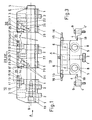
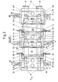
- Fig.1 einen Längsschnitt durch eine erfindungsgemässe Mehrfach-Spannvorrichtung,
- Fig.2 einen Grundriss der Spannvorrichtung gemäss Fig.1, und
- Fig.3 eine Stirnansicht der Spannvorrichtung gemäss der Pfeile A in den Fig.1 und 2 .
- 1 shows a longitudinal section through a multiple clamping device according to the invention,
- 2 shows a plan view of the clamping device according to FIG. 1, and
- 3 shows an end view of the tensioning device according to arrows A in FIGS. 1 and 2.
Gleiche Teile des Erfindungsgegenstandes sind in den Figuren mit denselben Bezugszeichen versehen.Identical parts of the subject matter of the invention are provided with the same reference symbols in the figures.
Fig.1, 2 und 3 zeigen in verschiedenen Ansichten eine Mehrfach-Spannvorrichtung, die aus einem Spannbock 10, mindestens einem Spannstück 20,20′,... und einem Spann-Endstück 30 besteht und zusammen mit einem Führungsachsenpaar 5 , eine Spanneinheit 5;10;20,20′,...;30 bildet. Der Spannbock 10 wird auf einem (nicht dargestellten) Maschinentisch fest gelagert und mittels je einer Befestigungsschraube 8 werden die beiden austauschbar ausgebildeten Führungsachsen 5 gehalten. Die Spannstücke 20,20′,... bzw. das Spann-Endstück 30 sind über das Führungsachsenpaar 5 längsverschiebbar einstellbar, wobei die Führungsachsen 5 über deren Gesamtlänge nach oben hin eine abgeflachte Auflagefläche 6 aufweisen. Die Spannstücke 20,20′,... und das Spann-Endstück 30 sind mittels Arretierschrauben 7 durch Angreifen an die abgeflachten Teile 6 der Führungsachsen 5 fixierbar ausgebildet.Fig. 1, 2 and 3 show in different views a multiple clamping device, which consists of a
Die Führungsachsen 5 können entsprechend der axialen Länge der Werkzeugmaschine ausgetauscht werden, so dass die Spanneinheit 5;10;20,20′,...;30 unabhängig von der Länge des Maschinentisches optimal einsetzbar ist.The
Die einzelnen Spannteile 10;20,20′,...;30 sind über Nutensteine 1 in Tischnuten geführt bzw. können mittels der T-Nutensteine 2 und der Spannschrauben 3 auf den Maschinentisch aufgespannt werden, wobei beispielsweise der Spannbock 10 mittels zwei Spannschrauben 3 aufgespannt werden kann, um eine einwandfreie Halterung von Werkstücken 35 zu gewährleisten.The
Innenstirnseitig und oberhalb der gesamten Breite des Spannbockes 10 ist zur Halterung des Werkstückes 35 eine Haltebacke 11 auf einer Unterlage 13 starr angeordnet. Jedes Spannstück 20,20′,... ist einmal stirnseitig axial zum Spannbock 10 bzw. zum vorhergehenden Spannstück 20,20′,... mit einer als Spannplatte mit einer Keilspannschräge 22 ausgebildeten Spannbacke 21 und mit einer, eine Ausnehmung aufweisenden Unterlage 13′ versehen, die durch vier Federn 24, vorzugsweise Wendelfedern, abgefedert ist, und zum anderen stirnseitig axial zum Spann-Endstück 30 analog zum Spannbock 10 mit daran starr angeordneter Haltebacke 11 mit der Unterlage 13 verbunden. Die Federn 24 der Spannbacken 21 erleichtern ein genaues Einspannen und Ausspannen der fertig bearbeiteten Werkstücke 35. Das Spann-Endstück 30 weist innenstirnseitig axial zum letzten Spannstück 20,20′,... ebenfalls die abgefederte Spannbacke 21 mit der mit einer Ausnehmung versehenen Unterlage 13′ auf. Die starren Haltebacken 11 sind durch Schrauben 12 - der Uebersichtlichkeit halber nur durch Schraubenachsen angedeutet - am Spannbockkörper 10 bzw. am Spannstück-Körper 20,20′,..., sowie die Unterlagen 13, bzw.13′ durch Schrauben 14 - angedeutet wie vorstehend - jeweils an der Haltebacke 11 bzw. an der Spannbacke 21 befestigt.A
Die abgefederten Spannbacken 21 sind durch schräg nach unten verlaufende Spannschrauben 23 und durch die Keilspannschräge 22 axial zum Werkstück 35 spannbar. Der Spannbock 10 und die Spannstücke 20,20′,... weisen beidseitig des Führungspaares 5 je einen Anschlaghalter 15 mit radial verstellbaren Anschlägen 16 auf, die vorzugsweise als Stifte ausgebildet sind und zur Einstellung der Werkstücke 35 in radialer Richtung dienen.The sprung
Zwischen der als Spannplatte keilförmig ausgebildeten Spannbacke 21 und dem Spannstück-Körper 20,20′,... bzw. dem Spann-Endstück-Körper 30 ist jeweils ein O-Ring 25 angeordnet, so dass eine Reinhaltung der Spanneinheit 5;10;20,20′,...;30 auch während des Betriebes gewährleistet ist.Between the wedge-shaped
Durch die wählbare Länge der Führungsachsen 5 kann die Spanneinheit 5;10;20,20′,...;30 jeweils der gesamten zur Verfügung stehenden Tischlänge der Werkzeugmaschine angepasst werden. Je nach Grösse und Form der zu bearbeitenden Werkstücke 35 können zusätzliche Mehrfach-Spannvorrichtungen 5;10;20,20′,...;30 parallel zueinander und radial zum Maschinentisch angeordnet werden, so dass dessen optimale Ausnützung stets gewährleistet ist.Due to the selectable length of the
Der Spannbock 10, die Spannstücke 20,20′,... und das Spann-Endstück 30 sind derart ausgebildet, dass auch eine zum Maschinentisch beliebige Schrägaufspannung möglich ist, indem jedes dieser Spannteile 10;20,20′,...;30 in Axialrichtung beidseitig Spannflächen 19,29,39 aufweist. Mittels auf die Spannflächen 19,29,39 angreifenden Spannbriden 4 ist die Spanneinheit 5;10;20,20′,...;30 durch Schlitze 4′ der Spannbriden 4 geführte Spannelemente 9, beispielsweise durch Schraubenmuttern, mit den in den Tischnuten geführten T-Nutensteinen auf dem Maschinentisch fixierbar.The
In den Fig.1 bis 3 sind sowohl die Spannschrauben 3 als auch die Spannelemente 9 mit den Spannbriden 4 dargestellt. In der Regel ist jede Spanneinheit 5;10;20,20′,...;30 entweder mittels Spannschrauben 3 oder mittels auf die Spannflächen 19,29,39 angreifenden Spannbriden 4 mit den in den Tischnuten geführten T-Nutensteinen 2 fixierbar. Bei besonderen Werkstückformen ist jedoch auch von Vorteil die Fixierung der Spanneinheit 5;10;20,20′,...;30 kombiniert teilweise mit Spannschrauben 3 und teilweise mittels Spannbriden 4 mit Spanelementen 9 vorzunehmen, wodurch eine Anfertigung von kostenaufwendigen Sonderspannmitteln vermieden wird.1 to 3, both the
- 1 Nutensteine1 sliding blocks
- 2 T-Nutensteine2 T-nuts
- 3 Spannschrauben, vertikal verlaufende3 clamping screws, vertically running
- 4 Spannbriden4 clamps
- 4′ Schlitze4 ′ slots
- 5 Führungsachsenpaar5 pair of guide axes
- 6 Auflageflächen6 contact surfaces
- 7 Arretierschrauben7 locking screws
- 8 Befestigungsschrauben8 fastening screws
- 9 Spannelemente, z.B. Schraubenmuttern9 clamping elements, e.g. Nuts
- 10 Spannbock10 clamp
- 11 Haltebacken11 holding jaws
- 12 Schrauben (nur durch Schraubenachsen angedeutet)12 screws (only indicated by screw axes)
- 13,13′ Unterlagen13,13 ′ documents
- 14 Schrauben (nur durch Schraubenachsen angedeutet)14 screws (only indicated by screw axes)
- 15 Anschlaghalter15 stop bracket
- 16 Anschläge, vorzugsweise Stifte16 stops, preferably pins
- 1717th
- 1818th
- 19 Spannflächen, ebene, zum Spannen des Spannbockes mittels Spannbriden19 clamping surfaces, flat, for clamping the clamp using clamps
- 20,20′,... Spannstücke (dargestellt nur 20)20.20 ′, ... clamping pieces (only 20 shown)
- 21 Spannbacken21 jaws
- 22 Keilspannschrägen22 tapered bevels
- 23 Spannschrauben, schräg verlaufende23 tensioning screws, inclined
- 24 Federn, vorzugsweise Wendelfedern24 springs, preferably helical springs
- 25 0-Ring25 0-ring
- 2626
- 2727th
- 2828
- 29 Spannflächen, ebene, zum Spannen der Spannstücke mittels Spannbriden29 clamping surfaces, flat, for clamping the clamping pieces using clamping clips
-
30 Spann-Endstück 5;10;20,20′,...;30 Spanneinheit30 clamping
end piece 5; 10; 20.20 ′, ...; 30 clamping unit - 35 Werkstücke (strichliert angedeutet)35 workpieces (indicated by dashed lines)
- 39 Spannflächen, ebene, zum Spannen des Spann-Endstückes mittels Spannbriden39 clamping surfaces, flat, for clamping the clamping end piece using clamping clips
Claims (8)
Priority Applications (1)
| Application Number | Priority Date | Filing Date | Title |
|---|---|---|---|
| AT88202351T ATE97050T1 (en) | 1988-01-05 | 1988-10-21 | MULTIPLE CLAMPING DEVICE. |
Applications Claiming Priority (2)
| Application Number | Priority Date | Filing Date | Title |
|---|---|---|---|
| CH17/88 | 1988-01-05 | ||
| CH1788 | 1988-01-05 |
Publications (3)
| Publication Number | Publication Date |
|---|---|
| EP0328792A2 true EP0328792A2 (en) | 1989-08-23 |
| EP0328792A3 EP0328792A3 (en) | 1990-05-30 |
| EP0328792B1 EP0328792B1 (en) | 1993-11-10 |
Family
ID=4177509
Family Applications (1)
| Application Number | Title | Priority Date | Filing Date |
|---|---|---|---|
| EP88202351A Expired - Lifetime EP0328792B1 (en) | 1988-01-05 | 1988-10-21 | Multiple clamping device |
Country Status (5)
| Country | Link |
|---|---|
| US (1) | US4930760A (en) |
| EP (1) | EP0328792B1 (en) |
| JP (1) | JP2704420B2 (en) |
| AT (1) | ATE97050T1 (en) |
| DE (3) | DE8816776U1 (en) |
Cited By (7)
| Publication number | Priority date | Publication date | Assignee | Title |
|---|---|---|---|---|
| GB2245202A (en) * | 1990-06-19 | 1992-01-02 | Mituo Izumi | A vice |
| GB2247423A (en) * | 1990-08-30 | 1992-03-04 | Rationella Maski Ingf | Multiple workpiece clamping apparatus |
| FR2689429A1 (en) * | 1992-04-06 | 1993-10-08 | Evard Precision Sa | Modular clamping vice - has fluted base rail supporting complementary supports, carrying jaws, which can be indexed along rail |
| WO1993019892A1 (en) * | 1992-03-30 | 1993-10-14 | Werkzeug- Und Apparatebau Mosig Heinz | Multiple workpiece holding fixture |
| US5280893A (en) * | 1990-08-30 | 1994-01-25 | Roland Sixtensson | Fixture for holding one or more articles |
| EP1043124A1 (en) * | 1999-04-09 | 2000-10-11 | Guido Hofer Machinentechnik | Device for clamping workpieces |
| WO2017092975A1 (en) * | 2015-12-03 | 2017-06-08 | Röthlisberger Oskar | Apparatus for clamping a plurality of workpieces on an indexing attachment of a machine tool |
Families Citing this family (20)
| Publication number | Priority date | Publication date | Assignee | Title |
|---|---|---|---|---|
| US5324013A (en) * | 1993-01-05 | 1994-06-28 | Marino Michael L | Clamping mechanism |
| CN102649233A (en) * | 2012-04-28 | 2012-08-29 | 苏州金牛精密机械有限公司 | Length machining rapid clamp for batch small work pieces |
| US9300003B2 (en) * | 2013-08-05 | 2016-03-29 | Lg Chem, Ltd. | Meandering correction apparatus for electrode assembly |
| US9636801B1 (en) * | 2013-10-30 | 2017-05-02 | Glacern Machine Tools, LLC | Vise system having modular mechanism and method of manufacture thereof |
| US10882161B2 (en) * | 2014-01-22 | 2021-01-05 | Timothy Hopey | Floating jaw assembly for use with machinist vises |
| CN104589105A (en) * | 2015-01-20 | 2015-05-06 | 优德精密工业(昆山)股份有限公司 | Bushing edge trimming machining tool and machining method |
| US9687913B1 (en) | 2016-11-03 | 2017-06-27 | Lawrence D. Smith | I. D. collet |
| CN107297696A (en) * | 2017-06-30 | 2017-10-27 | 苏州惠琪特电子科技有限公司 | A kind of bearing block fixture |
| CN107457591A (en) * | 2017-08-10 | 2017-12-12 | 广东长盈精密技术有限公司 | Fixture and CNC processing equipment provided with the fixture |
| CN108972060A (en) * | 2018-08-24 | 2018-12-11 | 安徽铭海通科技有限公司 | A kind of fixture for handware processing |
| CN108972061A (en) * | 2018-08-27 | 2018-12-11 | 芜湖文青机械设备设计有限公司 | A kind of automation fixture |
| CN109227174B (en) * | 2018-11-12 | 2024-06-18 | 杰纬特智能制造(苏州)有限公司 | CNC (computerized numerical control) multi-piece integrated machining combined clamp and clamping method |
| CN109514308A (en) * | 2018-12-29 | 2019-03-26 | 河南卫华重型机械股份有限公司 | A kind of long narrow workpiece Milling Process tooling |
| CN211414440U (en) * | 2019-11-04 | 2020-09-04 | 森海汽车部件(昆山)有限公司 | A CNC quick positioning fixture |
| CN112045461A (en) * | 2020-08-21 | 2020-12-08 | 江南工业集团有限公司 | Control surface milling device capable of clamping multiple control pieces and control surface milling method |
| CN112276783A (en) * | 2020-11-11 | 2021-01-29 | 上汽通用汽车有限公司 | Cylinder hole honing clamping device |
| CN112296716B (en) * | 2020-11-24 | 2024-09-03 | 锦州华一精工有限公司 | Claw utmost point final forging mould blank processing frock |
| CN112975788A (en) * | 2021-04-01 | 2021-06-18 | 周亮 | Clamping tool for medical treatment with adjustable clamping jaw convenient to use |
| CN113086626B (en) * | 2021-04-19 | 2023-01-17 | 苏州磐岩精密机械有限公司 | Synchronous clamping and loosening mechanism |
| WO2024132192A1 (en) * | 2022-12-22 | 2024-06-27 | Sew-Eurodrive Gmbh & Co. Kg | Holding device for holding a workpiece to be machined |
Family Cites Families (14)
| Publication number | Priority date | Publication date | Assignee | Title |
|---|---|---|---|---|
| US2511843A (en) * | 1950-06-20 | Screw-actuated vise jaw quickly | ||
| US2662433A (en) * | 1950-02-08 | 1953-12-15 | Caroline A Braun | Device for simultaneously clamping and releasing plural workpieces |
| DE1846198U (en) * | 1961-10-18 | 1962-02-01 | Lorenz Maier | MACHINE VICE. |
| DE1283169B (en) * | 1964-09-25 | 1968-11-14 | Franz Arnold | Machine vice with deep clamping jaws |
| AT291708B (en) * | 1967-12-21 | 1971-07-26 | Avesta Jernverks Ab | Welding electrode for electric arc welding |
| DE1983371U (en) * | 1968-02-05 | 1968-04-11 | Julius Paersch | ADJUSTABLE CLAMPING DEVICE FOR MACHINING VARIOUS WORKPIECE SIZES, IN PARTICULAR FOR FACE MILLING. |
| DE2453249C3 (en) * | 1974-11-09 | 1981-03-19 | Hörmann, Georg, 8948 Mindelheim | Machine vise |
| US4066250A (en) * | 1976-12-08 | 1978-01-03 | Campbell James B | Ski clamping apparatus |
| US4241906A (en) * | 1979-11-13 | 1980-12-30 | Cole Duane S | Ski vise |
| US4341375A (en) * | 1981-05-04 | 1982-07-27 | Mario Romanin | Dual vise for skis and the like |
| JPS58126140U (en) * | 1982-02-19 | 1983-08-27 | 相生精機株式会社 | Screw tightening inclined surface boost type clamp |
| US4445678A (en) * | 1982-05-24 | 1984-05-01 | George Irwin S | Precision aligned split V-block |
| DE8333285U1 (en) * | 1983-11-19 | 1984-02-23 | Meissner, Horst, 7000 Stuttgart | DEVICE FOR QUICKLY CLAMPING SKIS OF DIFFERENT WIDTH |
| US4643411A (en) * | 1985-08-23 | 1987-02-17 | Mitsuo Izumi | Vise for clamping two works |
-
1988
- 1988-02-11 DE DE8816776U patent/DE8816776U1/en not_active Expired - Lifetime
- 1988-02-11 DE DE3804270A patent/DE3804270A1/en not_active Withdrawn
- 1988-10-21 AT AT88202351T patent/ATE97050T1/en not_active IP Right Cessation
- 1988-10-21 EP EP88202351A patent/EP0328792B1/en not_active Expired - Lifetime
- 1988-10-21 DE DE88202351T patent/DE3885602D1/en not_active Expired - Fee Related
- 1988-12-28 JP JP63329533A patent/JP2704420B2/en not_active Expired - Lifetime
-
1989
- 1989-01-05 US US07/293,336 patent/US4930760A/en not_active Expired - Fee Related
Cited By (11)
| Publication number | Priority date | Publication date | Assignee | Title |
|---|---|---|---|---|
| GB2245202A (en) * | 1990-06-19 | 1992-01-02 | Mituo Izumi | A vice |
| DE4120002A1 (en) * | 1990-06-19 | 1992-01-02 | Mitsuo Izumi | VICE |
| GB2245202B (en) * | 1990-06-19 | 1994-03-23 | Mituo Izumi | A vice |
| GB2247423A (en) * | 1990-08-30 | 1992-03-04 | Rationella Maski Ingf | Multiple workpiece clamping apparatus |
| FR2666267A1 (en) * | 1990-08-30 | 1992-03-06 | Rationella Maski Ingf | FASTENING FOR THE TIGHTENING OF MULTIPLE WORKPIECES FOR MACHINING. |
| US5280893A (en) * | 1990-08-30 | 1994-01-25 | Roland Sixtensson | Fixture for holding one or more articles |
| GB2247423B (en) * | 1990-08-30 | 1994-09-28 | Rationella Maski Ingf | Apparatus for the clamping of a plurality of workpieces |
| WO1993019892A1 (en) * | 1992-03-30 | 1993-10-14 | Werkzeug- Und Apparatebau Mosig Heinz | Multiple workpiece holding fixture |
| FR2689429A1 (en) * | 1992-04-06 | 1993-10-08 | Evard Precision Sa | Modular clamping vice - has fluted base rail supporting complementary supports, carrying jaws, which can be indexed along rail |
| EP1043124A1 (en) * | 1999-04-09 | 2000-10-11 | Guido Hofer Machinentechnik | Device for clamping workpieces |
| WO2017092975A1 (en) * | 2015-12-03 | 2017-06-08 | Röthlisberger Oskar | Apparatus for clamping a plurality of workpieces on an indexing attachment of a machine tool |
Also Published As
| Publication number | Publication date |
|---|---|
| JPH01216735A (en) | 1989-08-30 |
| ATE97050T1 (en) | 1993-11-15 |
| US4930760A (en) | 1990-06-05 |
| JP2704420B2 (en) | 1998-01-26 |
| DE3885602D1 (en) | 1993-12-16 |
| EP0328792B1 (en) | 1993-11-10 |
| DE3804270A1 (en) | 1989-07-13 |
| DE8816776U1 (en) | 1991-01-24 |
| EP0328792A3 (en) | 1990-05-30 |
Similar Documents
| Publication | Publication Date | Title |
|---|---|---|
| EP0328792A2 (en) | Multiple clamping device | |
| DE69737933T2 (en) | DOUBLE ADJUSTABLE SCREW | |
| EP0742081B1 (en) | Universal precision vice for a machine tool | |
| DE69212871T2 (en) | Jig | |
| EP0149429A2 (en) | Apparatus for holding a work piece in a desired spatial position | |
| DD240859A5 (en) | MACHINE VICE | |
| EP0901884B1 (en) | Clamping device, specially vice | |
| EP0121134B1 (en) | Multipurpose clamping tool for processing workpieces, in particular wooden ones | |
| DE3211224C1 (en) | Clamping device for the workpiece on a machine for processing flat workpieces by cutting | |
| DE102018007186B4 (en) | Clamping jaw system | |
| DE2620658C2 (en) | Clamping device for the mutual clamping of workpieces | |
| DE326105C (en) | Clamping device for metalworking machines | |
| DE3201738A1 (en) | Machining table for DIY enthusiasts | |
| DE835876C (en) | For holding workpieces etc. Like. Specific facility | |
| DE469099C (en) | Clamping device for serial processing of metal parts | |
| DE202006011245U1 (en) | Clamping system e.g. for tool machines, has two or four facing, prism shaped clamping parts arranged in narrow clamping area over entire workpiece length | |
| DE2323054C3 (en) | Device for fastening grooved plates or the like for receiving control cams on machine tools or on presetting devices | |
| DE19839879A1 (en) | Multiple tensioning device for tensioning workpieces to be machined on a NC-machine | |
| DE1179879B (en) | Device for the simultaneous clamping of several similar and equally large workpieces | |
| DE828943C (en) | Jaws for a clamping device for workpieces | |
| DE1477457B2 (en) | DEVICE FOR ADJUSTING FOUR STEEL TOOLS IN A LATHE | |
| DE936784C (en) | Face milling cutter with exchangeable cutting tools | |
| DE302789C (en) | ||
| DE2033390C3 (en) | Adjustment device for tools of lathes | |
| DE3044290C2 (en) | Workbench |
Legal Events
| Date | Code | Title | Description |
|---|---|---|---|
| PUAI | Public reference made under article 153(3) epc to a published international application that has entered the european phase |
Free format text: ORIGINAL CODE: 0009012 |
|
| AK | Designated contracting states |
Kind code of ref document: A2 Designated state(s): AT BE CH DE ES FR GB GR IT LI LU NL SE |
|
| RBV | Designated contracting states (corrected) |
Designated state(s): AT BE CH DE ES FR GB IT LI NL SE |
|
| PUAL | Search report despatched |
Free format text: ORIGINAL CODE: 0009013 |
|
| AK | Designated contracting states |
Kind code of ref document: A3 Designated state(s): AT BE CH DE ES FR GB IT LI NL SE |
|
| 17P | Request for examination filed |
Effective date: 19900924 |
|
| 17Q | First examination report despatched |
Effective date: 19910924 |
|
| GRAA | (expected) grant |
Free format text: ORIGINAL CODE: 0009210 |
|
| AK | Designated contracting states |
Kind code of ref document: B1 Designated state(s): AT BE CH DE ES FR GB IT LI NL SE |
|
| PG25 | Lapsed in a contracting state [announced via postgrant information from national office to epo] |
Ref country code: SE Effective date: 19931110 Ref country code: NL Effective date: 19931110 Ref country code: ES Free format text: THE PATENT HAS BEEN ANNULLED BY A DECISION OF A NATIONAL AUTHORITY Effective date: 19931110 Ref country code: BE Effective date: 19931110 |
|
| REF | Corresponds to: |
Ref document number: 97050 Country of ref document: AT Date of ref document: 19931115 Kind code of ref document: T |
|
| REF | Corresponds to: |
Ref document number: 3885602 Country of ref document: DE Date of ref document: 19931216 |
|
| ITF | It: translation for a ep patent filed | ||
| GBT | Gb: translation of ep patent filed (gb section 77(6)(a)/1977) |
Effective date: 19940119 |
|
| ET | Fr: translation filed | ||
| NLV1 | Nl: lapsed or annulled due to failure to fulfill the requirements of art. 29p and 29m of the patents act | ||
| PLBE | No opposition filed within time limit |
Free format text: ORIGINAL CODE: 0009261 |
|
| STAA | Information on the status of an ep patent application or granted ep patent |
Free format text: STATUS: NO OPPOSITION FILED WITHIN TIME LIMIT |
|
| 26N | No opposition filed | ||
| PGFP | Annual fee paid to national office [announced via postgrant information from national office to epo] |
Ref country code: FR Payment date: 19961024 Year of fee payment: 9 |
|
| PGFP | Annual fee paid to national office [announced via postgrant information from national office to epo] |
Ref country code: CH Payment date: 19961025 Year of fee payment: 9 |
|
| PGFP | Annual fee paid to national office [announced via postgrant information from national office to epo] |
Ref country code: DE Payment date: 19961026 Year of fee payment: 9 |
|
| PGFP | Annual fee paid to national office [announced via postgrant information from national office to epo] |
Ref country code: GB Payment date: 19961028 Year of fee payment: 9 |
|
| PGFP | Annual fee paid to national office [announced via postgrant information from national office to epo] |
Ref country code: AT Payment date: 19961031 Year of fee payment: 9 |
|
| PG25 | Lapsed in a contracting state [announced via postgrant information from national office to epo] |
Ref country code: GB Free format text: LAPSE BECAUSE OF NON-PAYMENT OF DUE FEES Effective date: 19971021 Ref country code: AT Free format text: LAPSE BECAUSE OF NON-PAYMENT OF DUE FEES Effective date: 19971021 |
|
| PG25 | Lapsed in a contracting state [announced via postgrant information from national office to epo] |
Ref country code: LI Free format text: LAPSE BECAUSE OF NON-PAYMENT OF DUE FEES Effective date: 19971031 Ref country code: FR Free format text: THE PATENT HAS BEEN ANNULLED BY A DECISION OF A NATIONAL AUTHORITY Effective date: 19971031 Ref country code: CH Free format text: LAPSE BECAUSE OF NON-PAYMENT OF DUE FEES Effective date: 19971031 |
|
| GBPC | Gb: european patent ceased through non-payment of renewal fee |
Effective date: 19971021 |
|
| REG | Reference to a national code |
Ref country code: CH Ref legal event code: PL |
|
| PG25 | Lapsed in a contracting state [announced via postgrant information from national office to epo] |
Ref country code: DE Free format text: LAPSE BECAUSE OF NON-PAYMENT OF DUE FEES Effective date: 19980701 |
|
| REG | Reference to a national code |
Ref country code: FR Ref legal event code: ST |
|
| PG25 | Lapsed in a contracting state [announced via postgrant information from national office to epo] |
Ref country code: IT Free format text: LAPSE BECAUSE OF NON-PAYMENT OF DUE FEES;WARNING: LAPSES OF ITALIAN PATENTS WITH EFFECTIVE DATE BEFORE 2007 MAY HAVE OCCURRED AT ANY TIME BEFORE 2007. THE CORRECT EFFECTIVE DATE MAY BE DIFFERENT FROM THE ONE RECORDED. Effective date: 20051021 |