EP0328647B1 - Roll crusher and method of crushing using the same - Google Patents
Roll crusher and method of crushing using the same Download PDFInfo
- Publication number
- EP0328647B1 EP0328647B1 EP88903931A EP88903931A EP0328647B1 EP 0328647 B1 EP0328647 B1 EP 0328647B1 EP 88903931 A EP88903931 A EP 88903931A EP 88903931 A EP88903931 A EP 88903931A EP 0328647 B1 EP0328647 B1 EP 0328647B1
- Authority
- EP
- European Patent Office
- Prior art keywords
- roll
- rolls
- crushing
- follower
- crushing chamber
- Prior art date
- Legal status (The legal status is an assumption and is not a legal conclusion. Google has not performed a legal analysis and makes no representation as to the accuracy of the status listed.)
- Expired - Lifetime
Links
Images



Classifications
-
- B—PERFORMING OPERATIONS; TRANSPORTING
- B02—CRUSHING, PULVERISING, OR DISINTEGRATING; PREPARATORY TREATMENT OF GRAIN FOR MILLING
- B02C—CRUSHING, PULVERISING, OR DISINTEGRATING IN GENERAL; MILLING GRAIN
- B02C4/00—Crushing or disintegrating by roller mills
- B02C4/28—Details
- B02C4/30—Shape or construction of rollers
-
- B—PERFORMING OPERATIONS; TRANSPORTING
- B02—CRUSHING, PULVERISING, OR DISINTEGRATING; PREPARATORY TREATMENT OF GRAIN FOR MILLING
- B02C—CRUSHING, PULVERISING, OR DISINTEGRATING IN GENERAL; MILLING GRAIN
- B02C4/00—Crushing or disintegrating by roller mills
- B02C4/02—Crushing or disintegrating by roller mills with two or more rollers
-
- B—PERFORMING OPERATIONS; TRANSPORTING
- B02—CRUSHING, PULVERISING, OR DISINTEGRATING; PREPARATORY TREATMENT OF GRAIN FOR MILLING
- B02C—CRUSHING, PULVERISING, OR DISINTEGRATING IN GENERAL; MILLING GRAIN
- B02C4/00—Crushing or disintegrating by roller mills
- B02C4/28—Details
- B02C4/283—Lateral sealing shields
-
- B—PERFORMING OPERATIONS; TRANSPORTING
- B02—CRUSHING, PULVERISING, OR DISINTEGRATING; PREPARATORY TREATMENT OF GRAIN FOR MILLING
- B02C—CRUSHING, PULVERISING, OR DISINTEGRATING IN GENERAL; MILLING GRAIN
- B02C4/00—Crushing or disintegrating by roller mills
- B02C4/28—Details
- B02C4/32—Adjusting, applying pressure to, or controlling the distance between, milling members
-
- B—PERFORMING OPERATIONS; TRANSPORTING
- B02—CRUSHING, PULVERISING, OR DISINTEGRATING; PREPARATORY TREATMENT OF GRAIN FOR MILLING
- B02C—CRUSHING, PULVERISING, OR DISINTEGRATING IN GENERAL; MILLING GRAIN
- B02C4/00—Crushing or disintegrating by roller mills
- B02C4/28—Details
- B02C4/42—Driving mechanisms; Roller speed control
-
- G—PHYSICS
- G03—PHOTOGRAPHY; CINEMATOGRAPHY; ANALOGOUS TECHNIQUES USING WAVES OTHER THAN OPTICAL WAVES; ELECTROGRAPHY; HOLOGRAPHY
- G03G—ELECTROGRAPHY; ELECTROPHOTOGRAPHY; MAGNETOGRAPHY
- G03G5/00—Recording-members for original recording by exposure, e.g. to light, to heat or to electrons; Manufacture thereof; Selection of materials therefor
- G03G5/02—Charge-receiving layers
- G03G5/04—Photoconductive layers; Charge-generation layers or charge-transporting layers; Additives therefor; Binders therefor
- G03G5/08—Photoconductive layers; Charge-generation layers or charge-transporting layers; Additives therefor; Binders therefor characterised by the photoconductive material being inorganic
- G03G5/082—Photoconductive layers; Charge-generation layers or charge-transporting layers; Additives therefor; Binders therefor characterised by the photoconductive material being inorganic and not being incorporated in a bonding material, e.g. vacuum deposited
- G03G5/08214—Silicon-based
- G03G5/08264—Silicon-based comprising seven or more silicon-based layers
Definitions
- the invention relates to a roll crusher for crushing rocks and ores, etc.
- US-A-3 497 321 discloses a machine for densifying and aggregating fine-granular mineral salt material in a rolling mill.
- the material is passed through the gap between two rollers, which are rotating in opposite direction.
- a hopper chute for supplying the material to be aggregated to the rollers a number of downwardly extending rods or tubes is supported, the lower ends of which terminate above the narrowest spot of the roller gap. Due to this construction and the dimension of the gap by the rolling operation highly densified material in the form of longitudinal strips with intermediate strips of non-densified fine-granular material are produced.
- JP-Y1-35-22688 discloses a flour mill having a rotating roll and an interlocking roll, interlocking with said rotating roll through a pair of reduction gears.
- Said reduction gear is rotatably supported by a shaft of said interlocking roll and comprises a clutch disposed between said reduction gear and said shaft of said interlocking roll. Whether or not the clutch is on or off the interlocking roll and the rotating roll are rotating with the same or different speeds, having different effects on the flour to be ground.
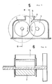
- the type of roll crusher has a crushing chamber 6 (a region indicated by chain line) as shown in Figs. 7a and 7b, whose longitudinal side faces 6a and 6b are formed respectively by the outer surfaces of the pair of rolls 2 and 3, and whose end faces 6c and 6d coincide with the openings formed in between the end faces 2a and 2b as well as 3a and 3b of said pair of respective rolls 2 and 3.
- the crushing chamber shown is an example for explanation, therefore not necessarily limited to the shape, but varying to a convenient space region depending on crushing condition.
- some roll crusher according to the prior art is provided with side plates called cheek plates to prevent crushed stock from flowing out from the end openings 6c and 6d of the crushing chamber 6.
- this type of roll crusher has no capability sufficient to prevent material being crushed from being pushed out of the crushing chamber 6 through the lower end portions of the end openings 6c and 6d (higher pressure applied on material to be crushed here), thus resulting in higher pressure applied on the rolls 2 and 3 at the roll center, and in lower pressure at both ends.
- JP-Y1-29 76 94 a comparable construction is disclosed in JP-Y1-29 76 94.
- This document refers to a guide made of bamboo for kneading vinyl.
- This guide is used in a kneading machine and comprises plates made of bamboo having a large number of bamboo strips. The plates are overlapped and adhered with each other so that the string of each bamboo strip crosses at an angle of 10° to 15° to the side edge of the guide.
- roll clearance is adjusted to be equal to or smaller than the particle size of desired products.
- Crushing mechanism according to the prior art may be described as follows. A clearance between a pair of opposing rolls 2 and 3, that is, crushing clearance S is smaller than particle diameter F of feed material to be crushed, and equal to or smaller than the particle diameter P of desirable products. Particles of material to be crushed are subjected to a continuously increasing compressive load and are eventually broken from the time when they come into contact with the surfaces of the pair of the opposing rolls to the time when they pass between the closest positions of the two opposing rolls.
- the roll crusher according to the prior art has a small crushing clearance S, thus limiting the throughput capacity of feed material through the crushing chamber, resulting in a low productivity of products.
- the smaller the particle size of desirable products the smaller the crushing clearance, thus further restricting the productivity.
- the object of the invention is to provide a uniform longitudinal (axial direction of rolls) pressure distribution in the crushing chamber for a high compression crushing effect and for prevention of partial wear of rolls in the axial direction thereof.
- the invention provides a roll crusher according the preamble of claim 1, being characterized by flanges fixed to the end surfaces of either roll for rotation with the roll, having a radius at least a crushing clearance between the rolls larger than that of the roll, and disposed to block end openings of aforesaid crushing chamber, as well as by stationary block members disposed to block an area of the end openings of aforesaid crushing chamber other than the area blocked by aforesaid flanges, and to prevent material to be crushed from flowing out of the end openings of the crushing chamber.
- a preferred embodiment of the invention provides a roll crusher, in which a pair of rolls facing each other is provided, feed material is supplied into a space formed in between these two rolls or a crushing chamber, and the feed material to be crushed is compressed for crushing while being rolled up with aforesaid pair of rolls, being characterized by one roll of aforesaid pair of rolls or a driver roll being power driven for rotation, and the other roll or a follower roll being rotated freely or at least together with the driver roll through the material rolled up in between the rolls while the material being crushed.
- Figs. 1 and 2 show an example of a roll crusher according to the invention.
- the same members as the roll crusher according to the prior art shown in Fig. 5 are given by the same numerals.
- the differences of a roll crusher according to the invention from the roll crusher according to the prior art are: block members or cheek plates 11 which prevent feed material to be crushed from flowing out of a crushing chamber 6 by blocking end surface openings 6c and 6d in the crushing chamber 6 (Fig. 7b), and flanges 12 which prevent the feed material to be crushed from being pushed out of the crushing chamber 6 through lower end portions under high pressure applied to the feed material to be crushed in the end surface openings 6c and 6d.
- the flanges 12 are fixed to end faces of one roll 3 for rotating together with the roll 3.
- the radius of the flange 12 is at least a crushing clearance in between the rolls larger than that of the roll 3. Because the flange 12 rotates integrally with the roll 3, there is little relative dislocation thereof to feed material to be compressed and crushed in between the rolls 2 and 3 under high pressure. As a result, there is little wear on the flange 12, permitting preservation of the function of the flange 12 to maintain the axially uniform pressure applied to the rolls 2 and 3 even under the progress of the wear of the rolls 2 and 3 after long service, thus preventing partial wear of the rolls 2 and 3, and maintaining a desirable interparticle crushing effect.
- a fixed plate 7 and a slide gate 8 are provided in a supply port 5 of feed material.
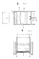
- a rod 9 is connected to the slide gate 8 as shown in Fig. 3.
- the movement of the rod 9 as shown in Arrow AA' can adjust the spacing between the fixed plate 7 and the slide gate 8, which in turn adjusts the amount of material to be fed into the crushing chamber from the supply port 5.
- the leading edge of the slide gate 8 is curved so that the section of the supply port 5 is wider in the end portions than the middle portion, which is to compensate short supply of material to the side wall portions of the supply port 5 (that is, both end portions of the crushing chamber 6) due to friction and to supply feed material uniformly over the length of the crushing chamber 6.
- the longitudinal length L of the supply port 5, as shown in Figs. 3 and 4 is designed essentially equal to the spacing between both flanges 12 of the roll 3 and slightly longer than the axial length L' of the roll 2. This, together with the curvature of the leading edge of the slide gate 8 as described above, is to supply feed material uniformly over the length of the rolls 2 and 3.
- a roll crusher shown in Fig. 1 uses the less worn flanges 12 to prevent feed material from being pushed out of the crushing chamber 6 in the axial direction of the rolls 2 and 3 by the compression force of the rolls 2 and 3, thus resulting in a uniform distribution of the pressure applied to the rolls 2 and 3 as well as of the compression force of particles of material to be crushed acting on each other, over the whole area of the longitudinal direction (roll axial direction) for a long period of service. As a result, partial wear of the rolls can be prevented for long, thus maintaining a desirable interparticle crushing effect.
- Fig. 9 shows a driving device to drive for rotation of particularly a pair of rolls 2 and 3.
- the roll 3 on the right side of the drawing is supported on a frame 1 with bearings BE1 and connected to a drive power such as the output shaft of a motor 10 through a coupling 19.
- the motor 10 drives the roll 3 for counterclockwise rotation in Fig. 1.
- the roll 2 on the left side of the drawing is supported with bearings BE2 rotatably (can be rotated freely).
- the relative positions of the rolls can be varied, that is, the rolls is brought closer or removed away, in order to adjust particle size of crushed products or to compensate wear of the rolls 2 and 3 to maintain a constant clearance of the rolls.
- the bearing BE2 supporting the follower roll 2 according to the invention is so fixed to the frame 1 that the bearing BE2 can be moved as shown by Arrow AA'.
- the roll 2 is rotating freely without any motor or other driving means provided, the movement of the bearing BE2 or the roll 2 is easily made, thus permitting a simple adjustment of crushing clearance of rolls.
- Fig. 10 shows another exampel of the driving device for the rolls 2 and 3.
- the same members as those shown in Fig. 9 are given by the same numerals.
- the follower roll 2 is connected to the driver roll 3 through a gear train 20, which transmits the rotational force of the driver roll 3 to the follower roll 2.
- the gear train 20 consists of, for instance, four gears 21, 22, 23 and 24 meshing with each other as shown in Fig. 11, and further a one-way clutch 25 is provided between the last gear 24 and the shaft 2a of the follower roll 2.
- the gear train 20 is so designed that the follower roll 2 rotates at a speed at least 5% slower than the driver roll 3.
- the one-way clutch 25 is installed to transmit the clockwise rotation of the last gear 24 (Fig. 11) to the roll shaft 2a, but not to transmit the adverse rotation.
- the motor 10 rotates the driver roll 3 counterclockwise in Fig. 11, at this time the follower roll 2 rotates clockwise at a speed at least 5% slower because of the gear train 20.
- the material to be crushed are rolled up in between the rolls 2 and 3 which have started rotation.
- the interference of the material adds up the rotation speed of the follower roll 2 nearly to that of the driver roll 3, then the one-way clutch 25 functions to allow the free rotation of the follower roll 2 without restricted by the rotation of the last gear 24 or the driver roll 3.
- each gear in the gear train 20 makes so-called racing.
- the gear train 20 intends only to transmit rotation during no load or light load, and only races during crushing. Therefore, it does not be required to transmit large torque and to have much strength, thus reducing additional cost.
- the position of the roll 2 can be shifted by rocking the idle gears 22 and 23 about the roll shaft 3a as shown by Arrow EE'.
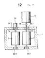
- Fig. 12 shows a further different embodiment for the driving device, in which the follower roll 2 of the embodiment in Fig. 9 is provided with an auxiliary motor 30 to drive.
- the auxiliary motor 30 can be turned ON or OFF as required by a controller (not shown). Switching the auxiliary motor 30 OFF allows the follower roll 2 to be rotated freely.
- a clutch can be introduced between the auxiliary motor 30 and the follower roll 2. ON or OFF of the clutch can switch the follower roll 2 to be rotated by the auxiliary motor 30 or freely.
- the rotational speed of the follower roll 2 by the auxiliary motor 30 may be the same as that of the driver roll 3 by the motor 10. Both speeds are not necessary the same, but, as in the case of Fig. 10, the follower roll 2 may be driven by the auxiliary motor 30 through a one-way clutch so that the rotation speed of the follower roll 2 is at least 5% slower than that of the driver roll 3.
- the auxiliary motor 30 When the rolls 2 and 3 are rotating under no load or light load, the auxiliary motor 30 is switched ON to rotate the follower roll 2, at this time, the driver roll 3 has already been driven by the motor 10. Under this condition, feed material is supplied in between the rolls 2 and 3, and crushing starts. Once crushing starts, the auxiliary motor 30 is turned OFF, and since then the follower roll 2 is brought into free rotation or rotating while following the driver roll 3 through material being crushed. Further crushing operation is performed under this conditions.
- the auxiliary motor 30 is energized to rotate the follower roll 2, but since this rotation does not require large torque, a very inexpensive motor can be used for the auxiliary motor 30, thus contributing no noticeable increase in cost. Therefore, as compared with the case when the rolls are independently driven, cost is lowered.
Landscapes
- Engineering & Computer Science (AREA)
- Food Science & Technology (AREA)
- Chemical & Material Sciences (AREA)
- Inorganic Chemistry (AREA)
- Physics & Mathematics (AREA)
- General Physics & Mathematics (AREA)
- Crushing And Grinding (AREA)
Abstract
Description
- The invention relates to a roll crusher for crushing rocks and ores, etc.
- US-A-3 497 321 discloses a machine for densifying and aggregating fine-granular mineral salt material in a rolling mill. The material is passed through the gap between two rollers, which are rotating in opposite direction. In a hopper chute for supplying the material to be aggregated to the rollers a number of downwardly extending rods or tubes is supported, the lower ends of which terminate above the narrowest spot of the roller gap. Due to this construction and the dimension of the gap by the rolling operation highly densified material in the form of longitudinal strips with intermediate strips of non-densified fine-granular material are produced.
- JP-Y1-35-22688 discloses a flour mill having a rotating roll and an interlocking roll, interlocking with said rotating roll through a pair of reduction gears. Said reduction gear is rotatably supported by a shaft of said interlocking roll and comprises a clutch disposed between said reduction gear and said shaft of said interlocking roll. Whether or not the clutch is on or off the interlocking roll and the rotating roll are rotating with the same or different speeds, having different effects on the flour to be ground.
- There has been known another type of roll crusher, as shown in Figs. 5 and 6, in which a pair of
rolls supply port 5 into the crushingchamber 6, that is, a space formed in between the pair of rolls, and the feed material supplied is crushed by compression while being rolled with said pair ofrolls - The type of roll crusher has a crushing chamber 6 (a region indicated by chain line) as shown in Figs. 7a and 7b, whose longitudinal side faces 6a and 6b are formed respectively by the outer surfaces of the pair of
rolls end faces respective rolls - On the other hand, some roll crusher according to the prior art is provided with side plates called cheek plates to prevent crushed stock from flowing out from the
end openings chamber 6. During the process of crushing by therolls chamber 6 through the lower end portions of theend openings rolls - Concerning such roll crushers with cheek plates, a comparable construction is disclosed in JP-Y1-29 76 94. This document refers to a guide made of bamboo for kneading vinyl. This guide is used in a kneading machine and comprises plates made of bamboo having a large number of bamboo strips. The plates are overlapped and adhered with each other so that the string of each bamboo strip crosses at an angle of 10° to 15° to the side edge of the guide.
- Repeated crushing with aforementioned different pressures distributed on the rollers may cause partial wear of the
rolls - Heretofore, in crushing rocks or ores by the roll crusher, to have a large crushing ratio, roll clearance is adjusted to be equal to or smaller than the particle size of desired products. Particularly for fine particle products, to have a large fraction of fine particles in crushed products, it was common for roll clearance to be adjusted to about 1/2 particle size of desired products. Crushing mechanism according to the prior art may be described as follows. A clearance between a pair of
opposing rolls - As stated above, the roll crusher according to the prior art has a small crushing clearance S, thus limiting the throughput capacity of feed material through the crushing chamber, resulting in a low productivity of products. Especially, the smaller the particle size of desirable products, the smaller the crushing clearance, thus further restricting the productivity.
- And, because feed material to be crushed is pressed by the
roll - The object of the invention is to provide a uniform longitudinal (axial direction of rolls) pressure distribution in the crushing chamber for a high compression crushing effect and for prevention of partial wear of rolls in the axial direction thereof.
- To achieve the object of the invention, the invention provides a roll crusher according the preamble of
claim 1, being characterized by flanges fixed to the end surfaces of either roll for rotation with the roll, having a radius at least a crushing clearance between the rolls larger than that of the roll, and disposed to block end openings of aforesaid crushing chamber, as well as by stationary block members disposed to block an area of the end openings of aforesaid crushing chamber other than the area blocked by aforesaid flanges, and to prevent material to be crushed from flowing out of the end openings of the crushing chamber. - To achieve a simplified mechanism for driving the rolls at reduced cost, a preferred embodiment of the invention provides a roll crusher, in which a pair of rolls facing each other is provided, feed material is supplied into a space formed in between these two rolls or a crushing chamber, and the feed material to be crushed is compressed for crushing while being rolled up with aforesaid pair of rolls, being characterized by one roll of aforesaid pair of rolls or a driver roll being power driven for rotation, and the other roll or a follower roll being rotated freely or at least together with the driver roll through the material rolled up in between the rolls while the material being crushed.
-
- Fig. 1 is a sectional side view of an embodiment according to the invention;
- Fig. 2 is a sectional plan view of Fig. 1 taken along line II-II;
- Fig. 3 is a top view of the roll crusher as shown in Fig. 1;
- Fig. 4 is a sectional view of Fig. 1 taken along line IV-IV;
- Figs. 5 and 6 are sectional views of the roll crusher according to the prior art;
- Figs. 7a and 7b are perspective views showing the crushing chamber;
- Fig. 8 is a view showing partial wear of rolls in the roll axial direction;
- Fig. 9 is a sectional view showing an example of the roll driving device;
- Fig. 10 is a sectional view showing another example of the roll driving device;
- Fig. 11 is a view showing the gear train for use in the device in Fig. 10; and
- Fig. 12 is a sectional view showing other example of the roll driving device.
- Figs. 1 and 2 show an example of a roll crusher according to the invention. In these drawings, the same members as the roll crusher according to the prior art shown in Fig. 5 are given by the same numerals. The differences of a roll crusher according to the invention from the roll crusher according to the prior art are: block members or
cheek plates 11 which prevent feed material to be crushed from flowing out of a crushingchamber 6 by blockingend surface openings flanges 12 which prevent the feed material to be crushed from being pushed out of the crushingchamber 6 through lower end portions under high pressure applied to the feed material to be crushed in theend surface openings flanges 12 are fixed to end faces of oneroll 3 for rotating together with theroll 3. The radius of theflange 12 is at least a crushing clearance in between the rolls larger than that of theroll 3. Because theflange 12 rotates integrally with theroll 3, there is little relative dislocation thereof to feed material to be compressed and crushed in between therolls flange 12, permitting preservation of the function of theflange 12 to maintain the axially uniform pressure applied to therolls rolls rolls - A
fixed plate 7 and aslide gate 8 are provided in asupply port 5 of feed material. Arod 9 is connected to theslide gate 8 as shown in Fig. 3. The movement of therod 9 as shown in Arrow AA' can adjust the spacing between thefixed plate 7 and theslide gate 8, which in turn adjusts the amount of material to be fed into the crushing chamber from thesupply port 5. The leading edge of theslide gate 8 is curved so that the section of thesupply port 5 is wider in the end portions than the middle portion, which is to compensate short supply of material to the side wall portions of the supply port 5 (that is, both end portions of the crushing chamber 6) due to friction and to supply feed material uniformly over the length of the crushingchamber 6. - The longitudinal length L of the
supply port 5, as shown in Figs. 3 and 4, is designed essentially equal to the spacing between bothflanges 12 of theroll 3 and slightly longer than the axial length L' of theroll 2. This, together with the curvature of the leading edge of theslide gate 8 as described above, is to supply feed material uniformly over the length of therolls - Sign BE in Fig. 2 is bearings for supporting the
rolls - A roll crusher shown in Fig. 1 uses the less
worn flanges 12 to prevent feed material from being pushed out of the crushingchamber 6 in the axial direction of therolls rolls rolls - Fig. 9 shows a driving device to drive for rotation of particularly a pair of
rolls roll 3 on the right side of the drawing is supported on aframe 1 with bearings BE1 and connected to a drive power such as the output shaft of amotor 10 through acoupling 19. Themotor 10 drives theroll 3 for counterclockwise rotation in Fig. 1. Theroll 2 on the left side of the drawing is supported with bearings BE2 rotatably (can be rotated freely). - In crushing, first one
roll 3 is rotated by themotor 10 counterclockwise in the Fig. 1. Then theother roll 2 is rotated clockwise in the drawing through the material being crushed in the crushingchamber 6. As a result, the stock is broken while being rolled up in between therolls follower roll 2 follows the drivingroll 3 and rotates at a nearly same speed as the drivingroll 3, crushing is positively performed without any trouble. Here, only one driving power is used for therolls - Incidentally, it is desirable that with a roll crusher the relative positions of the rolls can be varied, that is, the rolls is brought closer or removed away, in order to adjust particle size of crushed products or to compensate wear of the
rolls follower roll 2 according to the invention is so fixed to theframe 1 that the bearing BE2 can be moved as shown by Arrow AA'. In this case, because theroll 2 is rotating freely without any motor or other driving means provided, the movement of the bearing BE2 or theroll 2 is easily made, thus permitting a simple adjustment of crushing clearance of rolls. - Fig. 10 shows another exampel of the driving device for the
rolls - The
follower roll 2 is connected to thedriver roll 3 through agear train 20, which transmits the rotational force of thedriver roll 3 to thefollower roll 2. Thegear train 20 consists of, for instance, fourgears last gear 24 and theshaft 2a of thefollower roll 2. Thegear train 20 is so designed that thefollower roll 2 rotates at a speed at least 5% slower than thedriver roll 3. The one-way clutch 25 is installed to transmit the clockwise rotation of the last gear 24 (Fig. 11) to theroll shaft 2a, but not to transmit the adverse rotation. - In crushing, first, the
motor 10 rotates thedriver roll 3 counterclockwise in Fig. 11, at this time thefollower roll 2 rotates clockwise at a speed at least 5% slower because of thegear train 20. Supplied in between therolls rolls follower roll 2 nearly to that of thedriver roll 3, then the one-way clutch 25 functions to allow the free rotation of thefollower roll 2 without restricted by the rotation of thelast gear 24 or thedriver roll 3. At that time, each gear in thegear train 20 makes so-called racing. - With the embodiment in Fig. 9, because the
follower roll 2 does not rotate together with thedriver roll 3 at first, it may happen that, when entering feed material includes coarser particles, the coarser particles cannot be nipped, in other words, effective "nip angle" (the maximum nipping angle which allows crushing in between rolls) becomes smaller. On the contrary, with the embodiment in Fig. 10, in which thefollower roll 2 rotates at a lower speed from the beginning, there is no such chance as stated above. - Besides, the
gear train 20 intends only to transmit rotation during no load or light load, and only races during crushing. Therefore, it does not be required to transmit large torque and to have much strength, thus reducing additional cost. - As described above, it is desirable that at least one of the
rolls roll 2 can be shifted by rocking theidle gears roll shaft 3a as shown by Arrow EE'. - Fig. 12 shows a further different embodiment for the driving device, in which the
follower roll 2 of the embodiment in Fig. 9 is provided with anauxiliary motor 30 to drive. Theauxiliary motor 30 can be turned ON or OFF as required by a controller (not shown). Switching theauxiliary motor 30 OFF allows thefollower roll 2 to be rotated freely. Alternatively, a clutch can be introduced between theauxiliary motor 30 and thefollower roll 2. ON or OFF of the clutch can switch thefollower roll 2 to be rotated by theauxiliary motor 30 or freely. The rotational speed of thefollower roll 2 by theauxiliary motor 30 may be the same as that of thedriver roll 3 by themotor 10. Both speeds are not necessary the same, but, as in the case of Fig. 10, thefollower roll 2 may be driven by theauxiliary motor 30 through a one-way clutch so that the rotation speed of thefollower roll 2 is at least 5% slower than that of thedriver roll 3. - When the
rolls auxiliary motor 30 is switched ON to rotate thefollower roll 2, at this time, thedriver roll 3 has already been driven by themotor 10. Under this condition, feed material is supplied in between therolls auxiliary motor 30 is turned OFF, and since then thefollower roll 2 is brought into free rotation or rotating while following thedriver roll 3 through material being crushed. Further crushing operation is performed under this conditions. - As stated above, under no load or light load, the
auxiliary motor 30 is energized to rotate thefollower roll 2, but since this rotation does not require large torque, a very inexpensive motor can be used for theauxiliary motor 30, thus contributing no noticeable increase in cost. Therefore, as compared with the case when the rolls are independently driven, cost is lowered. - At the same time, since the
follower roll 2 is rotated beforehand under no load, as with the case in the device shown in Fig. 10, coarse particles of feed material can be crushed, in other words, a large effective nip angle can be maintained.
Claims (10)
- A roll crusher having a pair of rolls (2,3) facing each other, in which feed material to be crushed is fed into a space or a crushing chamber (6) formed in between these rolls (2,3), the pair of said rolls (2,3) rolls up the material to compress and crush, and blocking members (11) are fixedly disposed above and along the axial direction of said rolls (2,3) to block regions in the end openings (6c,6d) of said crushing chamber (6) characterized by
flanges (12) fixed to the end surfaces of one or the other of said rolls (2,3) for rotation together with said roll (2,3), and having a radius at least a crushing clearance larger than that of said roll (2,3) to block end openings of said crushing chamber (6), and
the blocking members (11) disposed to block regions in the end openings (6c,6d) of said crushing chamber (6) other than those covered by said flanges (12), and fixedly disposed to prevent feed material from flowing out of the end openings (6c,6d) of said crushing chamber (6). - A roll crusher as claimed in claim 1, wherein a feed opening (5) is provided to supply said feed material, and the length (L) in the roll axis direction of said feed opening (5) is essentially equal to the inside spacing of said blocking members (11).
- A roll crusher as claimed in claim 1 or claim 2, wherein an opening area for at least a part of the feed passage to feed said material can be adjusted.
- A roll crusher as claimed in one of claims 1 to 3, wherein at least some fractions of the passage to feed said material are wide in regions corresponding to the end portions of said crushing chamber (6) and narrow in the region corresponding to the center.
- A roll crusher as claimed in one of claims 1 to 4, in which the pair of said rolls (2,3) rolls up feed material to crush, comprising:
a driver roll (3), one of the pair of said rolls, being driven for rotation, and
a follower roll (2), the other roll, rotating freely put together with said driver roll (3) through the material rolled up in between said rolls at least while crushing is effected. - A roll crusher as claimed in claim 5, wherein said follower roll (2) is driven for rotation during no load or light load before crushing.
- A roll crusher as claimed in claim 6, wherein power transmission means (20) is provided in between said driver and follower rolls (3,2), and said follower roll (2) is rotated beforehand by transmitting the rotation of the said driver roll to said follower roll through said power transmission means (20).
- A roll crusher as claimed in claim 7, wherein said power transmission means (20) has a gear train (20) transmitting reduced rotation of said driver roll (3) to said follower roll (2), and a one-way clutch (25) disposed in between said gear train (20) and said follower roll (2) to transmit only a rotation toward a direction as involving feed material to said follower roll (2).
- A roll crusher as claimed in claim 6, wherein a small capacity of auxiliary motor (30) is provided to rotate said follower roll (2) beforehand.
- A roll crusher as claimed in claim 9, wherein a rotation speed of said follower roll (2) driven by said auxiliary motor (30) is slower than that of said driver roll (3), and a one-way clutch (25) is provided to transmit only a rotation toward a direction as involving feed material to said follower roll (2).
Priority Applications (1)
| Application Number | Priority Date | Filing Date | Title |
|---|---|---|---|
| EP92114046A EP0514953B1 (en) | 1987-04-28 | 1988-04-27 | Roll crusher and crushing method in use for the roll crusher |
Applications Claiming Priority (4)
| Application Number | Priority Date | Filing Date | Title |
|---|---|---|---|
| JP62103320A JPS63270556A (en) | 1987-04-28 | 1987-04-28 | Roll crusher |
| JP103321/87 | 1987-04-28 | ||
| JP103320/87 | 1987-04-28 | ||
| JP62103321A JPS63270555A (en) | 1987-04-28 | 1987-04-28 | Roll crusher |
Related Child Applications (2)
| Application Number | Title | Priority Date | Filing Date |
|---|---|---|---|
| EP92114046A Division-Into EP0514953B1 (en) | 1987-04-28 | 1988-04-27 | Roll crusher and crushing method in use for the roll crusher |
| EP92114046.3 Division-Into | 1992-08-18 |
Publications (3)
| Publication Number | Publication Date |
|---|---|
| EP0328647A1 EP0328647A1 (en) | 1989-08-23 |
| EP0328647A4 EP0328647A4 (en) | 1990-06-27 |
| EP0328647B1 true EP0328647B1 (en) | 1993-11-03 |
Family
ID=26443962
Family Applications (2)
| Application Number | Title | Priority Date | Filing Date |
|---|---|---|---|
| EP92114046A Expired - Lifetime EP0514953B1 (en) | 1987-04-28 | 1988-04-27 | Roll crusher and crushing method in use for the roll crusher |
| EP88903931A Expired - Lifetime EP0328647B1 (en) | 1987-04-28 | 1988-04-27 | Roll crusher and method of crushing using the same |
Family Applications Before (1)
| Application Number | Title | Priority Date | Filing Date |
|---|---|---|---|
| EP92114046A Expired - Lifetime EP0514953B1 (en) | 1987-04-28 | 1988-04-27 | Roll crusher and crushing method in use for the roll crusher |
Country Status (6)
| Country | Link |
|---|---|
| US (1) | US5088651A (en) |
| EP (2) | EP0514953B1 (en) |
| KR (1) | KR920003077B1 (en) |
| AU (2) | AU604324B2 (en) |
| DE (2) | DE3855619T2 (en) |
| WO (1) | WO1988008330A1 (en) |
Cited By (1)
| Publication number | Priority date | Publication date | Assignee | Title |
|---|---|---|---|---|
| WO2026068488A1 (en) * | 2024-09-25 | 2026-04-02 | Khd Humboldt Wedag Gmbh | Gate valve for a high-pressure roller press |
Families Citing this family (30)
| Publication number | Priority date | Publication date | Assignee | Title |
|---|---|---|---|---|
| EP0514953B1 (en) * | 1987-04-28 | 1996-10-16 | Nittetsu Mining Co., Ltd. | Roll crusher and crushing method in use for the roll crusher |
| FR2648366B2 (en) * | 1987-09-17 | 1994-06-03 | Fives Cail Babcock | PROCESS OF FINE GRINDING OF MINERALS AND CRUSHER FOR THE IMPLEMENTATION OF THIS PROCESS |
| US5054701A (en) * | 1989-06-20 | 1991-10-08 | Fives-Cail Babcock | Milling process and apparatus |
| US5027491A (en) * | 1990-08-16 | 1991-07-02 | Mclanahan Corporation | Roller |
| WO1993013858A1 (en) * | 1992-01-20 | 1993-07-22 | Eco Italia S.A.S. Di Basile Rodolfo & C. | Roller device for crumbling stripes of carcasses of worn tires |
| DE19637275A1 (en) * | 1996-09-13 | 1998-03-19 | Deutz Ag | Two-roller machine, in particular roller press for pressure treatment of granular goods |
| FR2759610B1 (en) | 1997-02-19 | 1999-04-16 | Fcb | METHOD AND INSTALLATION FOR REDUCING CRUDE MATERIAL INTO PIECES TO GRAIN MATERIAL ACCORDING TO A GIVEN GRANULOMETRIC DISTRIBUTION |
| FI116523B (en) * | 2004-09-07 | 2005-12-15 | Uniglass Engineering Oy | Method and apparatus for heating glass plate |
| US20060255197A1 (en) * | 2005-05-13 | 2006-11-16 | Mcivor Robert E | End closures |
| RU2498854C2 (en) * | 2008-07-02 | 2013-11-20 | Бюлер Аг | Method of flour production from grain, roll mill, application of roll mill, zigzag sieving machine and its application |
| EP2196559A1 (en) | 2008-12-15 | 2010-06-16 | ALSTOM Technology Ltd | Thermal barrier coating system, components coated therewith and method for applying a thermal barrier coating system to components |
| DE102011000748A1 (en) | 2011-02-15 | 2012-08-16 | Thyssenkrupp Polysius Ag | Roll mill and method for operating a roll mill |
| CN202137006U (en) * | 2011-05-09 | 2012-02-08 | 成都利君实业股份有限公司 | Roller of rolling machine |
| US8708264B2 (en) | 2012-04-20 | 2014-04-29 | Metso Minerals (Sweden) Ab | Roller crusher having at least one roller comprising a flange |
| DK2756886T3 (en) * | 2012-04-20 | 2017-09-25 | Metso Minerals (Sweden) Ab | Roll crusher with at least one roller comprising a flange. |
| US8695907B2 (en) * | 2012-04-20 | 2014-04-15 | Metso Minerals Industries, Inc. | Roller crusher with cheek plates |
| AU2013203833C1 (en) * | 2012-04-20 | 2015-09-24 | Metso Usa Inc. | Roller crusher having at least one roller comprising a flange |
| NZ703866A (en) * | 2012-07-19 | 2016-05-27 | Adamis Pharmaceuticals Corp | Powder feeding apparatus |
| US9205431B2 (en) | 2013-03-14 | 2015-12-08 | Joy Mm Delaware, Inc. | Variable speed motor drive for industrial machine |
| CN103599825A (en) * | 2013-11-30 | 2014-02-26 | 山东瑞泰新材料科技有限公司 | Crushing apparatus for spectral graphite electrode |
| CN103657788B (en) * | 2014-01-06 | 2015-02-18 | 江苏鹏飞集团股份有限公司 | Roller for roller press and roll system for roller press |
| CN104941720A (en) * | 2015-06-16 | 2015-09-30 | 顾广才 | Sawtooth crusher for ceramic production |
| CN106010776A (en) * | 2016-07-18 | 2016-10-12 | 海南大学 | Millerator for oil palm shells |
| ES2755484T3 (en) * | 2017-05-09 | 2020-04-22 | Buehler Ag | Feed and feed roller mill with one gear |
| CN108160195B (en) * | 2018-01-25 | 2024-01-26 | 宁夏天地奔牛实业集团有限公司 | Vertical double-roller crusher for underground coal mine |
| US11077446B2 (en) * | 2018-10-01 | 2021-08-03 | Metso Outotec USA Inc. | Startup sequence for roller crusher |
| US10857539B2 (en) * | 2018-10-17 | 2020-12-08 | General Mills Inc. | Apparatus and method for variable sizing of particulates |
| CN112936637B (en) * | 2021-01-29 | 2022-08-30 | 贵州大众橡胶有限公司 | Automobile rubber diaphragm processing device |
| FI131248B1 (en) | 2022-09-23 | 2025-01-08 | Aimo Kortteen Konepaja Oy | Roller mill and method for using a roller mill |
| FI131249B1 (en) | 2022-09-28 | 2025-01-08 | Aimo Kortteen Konepaja Oy | Roller mill and operating method for a roller mill |
Family Cites Families (17)
| Publication number | Priority date | Publication date | Assignee | Title |
|---|---|---|---|---|
| US198605A (en) * | 1877-12-25 | M achines | ||
| US942865A (en) * | 1909-03-17 | 1909-12-07 | August H Petersen | Grinding or pulverizing machine. |
| US1014383A (en) * | 1911-02-25 | 1912-01-09 | Jeremiah S Frazee | Crushing-rolls. |
| US2306427A (en) * | 1941-01-08 | 1942-12-29 | Julius B Christman | Gravel treating device |
| DE895094C (en) * | 1949-06-30 | 1954-01-18 | Zuendapp Werke G M B H | Roller mill for grinding grain and other grainy substances |
| DE1567974A1 (en) * | 1965-05-22 | 1970-10-22 | Kloeckner Humboldt Deutz Ag | Rolling mill for compacting and making pieces of fine-grain potash and / or rock salts |
| DE1757093C3 (en) * | 1968-03-29 | 1978-10-19 | Alpine Ag, 8900 Augsburg | Roller mill for fine grinding |
| JPS54145061A (en) * | 1978-05-02 | 1979-11-12 | Godo Seitetsu | Roll for crusher of aggregate consisting of pulverulent body |
| JPS5761547A (en) * | 1980-09-30 | 1982-04-14 | Matsushita Electric Works Ltd | Building material panel |
| US4377260A (en) * | 1980-10-24 | 1983-03-22 | Huffman Jon W | Roller mill drive |
| DE3302176A1 (en) * | 1983-01-24 | 1984-07-26 | Klöckner-Humboldt-Deutz AG, 5000 Köln | METHOD AND SYSTEM FOR CONTINUOUS PRESSURE REDUCTION OF SPROEDEN GROUND MATERIAL |
| DE3305339A1 (en) * | 1983-02-17 | 1984-08-23 | Klöckner-Humboldt-Deutz AG, 5000 Köln | METHOD AND DEVICE FOR CONTINUOUS PRESSURE REDUCTION SPROEDEN GROSSGUTES |
| IN167322B (en) * | 1985-06-26 | 1990-10-06 | Hitachi Shipbuilding Eng Co | |
| JPS62140946A (en) * | 1985-12-11 | 1987-06-24 | Nippon Seimitsu Kogyo Kk | Sheet feeding device |
| JPS62140946U (en) * | 1986-02-25 | 1987-09-05 | ||
| EP0514953B1 (en) * | 1987-04-28 | 1996-10-16 | Nittetsu Mining Co., Ltd. | Roll crusher and crushing method in use for the roll crusher |
| DE3731934A1 (en) * | 1987-09-23 | 1989-04-13 | Kloeckner Humboldt Deutz Ag | TWO-ROLLING MACHINE LIKE A ROLLING PRESS |
-
1988
- 1988-04-27 EP EP92114046A patent/EP0514953B1/en not_active Expired - Lifetime
- 1988-04-27 WO PCT/JP1988/000416 patent/WO1988008330A1/en not_active Ceased
- 1988-04-27 EP EP88903931A patent/EP0328647B1/en not_active Expired - Lifetime
- 1988-04-27 KR KR1019880701466A patent/KR920003077B1/en not_active Expired
- 1988-04-27 AU AU16895/88A patent/AU604324B2/en not_active Ceased
- 1988-04-27 DE DE3855619T patent/DE3855619T2/en not_active Expired - Fee Related
- 1988-04-27 DE DE88903931T patent/DE3885442T2/en not_active Expired - Fee Related
-
1990
- 1990-09-14 AU AU62539/90A patent/AU632621B2/en not_active Ceased
- 1990-09-28 US US07/590,562 patent/US5088651A/en not_active Expired - Lifetime
Cited By (1)
| Publication number | Priority date | Publication date | Assignee | Title |
|---|---|---|---|---|
| WO2026068488A1 (en) * | 2024-09-25 | 2026-04-02 | Khd Humboldt Wedag Gmbh | Gate valve for a high-pressure roller press |
Also Published As
| Publication number | Publication date |
|---|---|
| KR890700399A (en) | 1989-04-24 |
| EP0328647A4 (en) | 1990-06-27 |
| US5088651A (en) | 1992-02-18 |
| DE3855619T2 (en) | 1997-03-06 |
| AU6253990A (en) | 1990-12-13 |
| DE3885442T2 (en) | 1994-04-14 |
| EP0514953B1 (en) | 1996-10-16 |
| EP0514953A2 (en) | 1992-11-25 |
| KR920003077B1 (en) | 1992-04-13 |
| AU632621B2 (en) | 1993-01-07 |
| EP0328647A1 (en) | 1989-08-23 |
| EP0514953A3 (en) | 1993-04-14 |
| DE3855619D1 (en) | 1996-11-21 |
| DE3885442D1 (en) | 1993-12-09 |
| AU604324B2 (en) | 1990-12-13 |
| AU1689588A (en) | 1988-12-02 |
| WO1988008330A1 (en) | 1988-11-03 |
Similar Documents
| Publication | Publication Date | Title |
|---|---|---|
| US5088651A (en) | Roll crusher and crushing method in use for the roll crusher | |
| EP2207619B1 (en) | Method of, and apparatus for, the preliminary grinding and finishing of mineral and non-mineral materials | |
| US4703897A (en) | Method and apparatus for continuous pressure comminution of brittle grinding stock | |
| CA2315164C (en) | Method and device for fine grinding mineral and non-mineral substances | |
| US5205494A (en) | Grinding process and mill for carrying out this process | |
| US5054701A (en) | Milling process and apparatus | |
| US4905910A (en) | Double roll machine such as, for example, a roll press | |
| US1014383A (en) | Crushing-rolls. | |
| UA128117C2 (en) | Startup sequence for roller crusher | |
| US2959364A (en) | Comminution apparatus | |
| KR20090031028A (en) | Compact grinder | |
| CN220048315U (en) | Crushing device capable of conducting secondary crushing | |
| JP3379672B2 (en) | Roll machine | |
| US3199798A (en) | Crushers | |
| RU2036006C1 (en) | Pressing crusher | |
| US20010001670A1 (en) | Briquet forming machine and feeder system therefor | |
| US2738135A (en) | Roller mill with worm gear drive, operable through a range of adjustment positions of the rollers | |
| KR920010350B1 (en) | Crushing method using roll crusher and roll crusher | |
| CN108339606A (en) | Multistage roller grinding device for ground cereal | |
| EP1035923A1 (en) | Roller mill | |
| CN220737720U (en) | Quick pre-crushing device for graphite production | |
| JPS62241556A (en) | Crusher | |
| CN221287996U (en) | Heavy metal pulverizer | |
| US2834674A (en) | Method of making strip | |
| JPH0215557Y2 (en) |
Legal Events
| Date | Code | Title | Description |
|---|---|---|---|
| PUAI | Public reference made under article 153(3) epc to a published international application that has entered the european phase |
Free format text: ORIGINAL CODE: 0009012 |
|
| 17P | Request for examination filed |
Effective date: 19881214 |
|
| AK | Designated contracting states |
Kind code of ref document: A1 Designated state(s): BE DE FR GB IT NL |
|
| A4 | Supplementary search report drawn up and despatched |
Effective date: 19900627 |
|
| 17Q | First examination report despatched |
Effective date: 19910917 |
|
| GRAA | (expected) grant |
Free format text: ORIGINAL CODE: 0009210 |
|
| AK | Designated contracting states |
Kind code of ref document: B1 Designated state(s): BE DE FR GB IT NL |
|
| XX | Miscellaneous (additional remarks) |
Free format text: TEILANMELDUNG 92114046.3 EINGEREICHT AM 27/04/88. |
|
| ET | Fr: translation filed | ||
| REF | Corresponds to: |
Ref document number: 3885442 Country of ref document: DE Date of ref document: 19931209 |
|
| ITF | It: translation for a ep patent filed | ||
| PLBE | No opposition filed within time limit |
Free format text: ORIGINAL CODE: 0009261 |
|
| STAA | Information on the status of an ep patent application or granted ep patent |
Free format text: STATUS: NO OPPOSITION FILED WITHIN TIME LIMIT |
|
| 26N | No opposition filed | ||
| PGFP | Annual fee paid to national office [announced via postgrant information from national office to epo] |
Ref country code: FR Payment date: 20010409 Year of fee payment: 14 |
|
| PGFP | Annual fee paid to national office [announced via postgrant information from national office to epo] |
Ref country code: GB Payment date: 20010425 Year of fee payment: 14 |
|
| PGFP | Annual fee paid to national office [announced via postgrant information from national office to epo] |
Ref country code: NL Payment date: 20010430 Year of fee payment: 14 |
|
| PGFP | Annual fee paid to national office [announced via postgrant information from national office to epo] |
Ref country code: BE Payment date: 20010625 Year of fee payment: 14 |
|
| REG | Reference to a national code |
Ref country code: GB Ref legal event code: IF02 |
|
| PG25 | Lapsed in a contracting state [announced via postgrant information from national office to epo] |
Ref country code: GB Free format text: LAPSE BECAUSE OF NON-PAYMENT OF DUE FEES Effective date: 20020427 |
|
| PG25 | Lapsed in a contracting state [announced via postgrant information from national office to epo] |
Ref country code: BE Free format text: LAPSE BECAUSE OF NON-PAYMENT OF DUE FEES Effective date: 20020430 |
|
| PG25 | Lapsed in a contracting state [announced via postgrant information from national office to epo] |
Ref country code: NL Free format text: LAPSE BECAUSE OF NON-PAYMENT OF DUE FEES Effective date: 20021101 |
|
| GBPC | Gb: european patent ceased through non-payment of renewal fee |
Effective date: 20020427 |
|
| PG25 | Lapsed in a contracting state [announced via postgrant information from national office to epo] |
Ref country code: FR Free format text: LAPSE BECAUSE OF NON-PAYMENT OF DUE FEES Effective date: 20021231 |
|
| NLV4 | Nl: lapsed or anulled due to non-payment of the annual fee |
Effective date: 20021101 |
|
| REG | Reference to a national code |
Ref country code: FR Ref legal event code: ST |
|
| PGFP | Annual fee paid to national office [announced via postgrant information from national office to epo] |
Ref country code: DE Payment date: 20030508 Year of fee payment: 16 |
|
| PG25 | Lapsed in a contracting state [announced via postgrant information from national office to epo] |
Ref country code: DE Free format text: LAPSE BECAUSE OF NON-PAYMENT OF DUE FEES Effective date: 20041103 |
|
| PG25 | Lapsed in a contracting state [announced via postgrant information from national office to epo] |
Ref country code: IT Free format text: LAPSE BECAUSE OF NON-PAYMENT OF DUE FEES;WARNING: LAPSES OF ITALIAN PATENTS WITH EFFECTIVE DATE BEFORE 2007 MAY HAVE OCCURRED AT ANY TIME BEFORE 2007. THE CORRECT EFFECTIVE DATE MAY BE DIFFERENT FROM THE ONE RECORDED. Effective date: 20050427 |