EP0328162A2 - Überwachungsgerät für parentale Infusionen und Verfahren zur Überwachung eines eine Flüssigkeit paranteral zuführenden Systems - Google Patents
Überwachungsgerät für parentale Infusionen und Verfahren zur Überwachung eines eine Flüssigkeit paranteral zuführenden Systems Download PDFInfo
- Publication number
- EP0328162A2 EP0328162A2 EP89105436A EP89105436A EP0328162A2 EP 0328162 A2 EP0328162 A2 EP 0328162A2 EP 89105436 A EP89105436 A EP 89105436A EP 89105436 A EP89105436 A EP 89105436A EP 0328162 A2 EP0328162 A2 EP 0328162A2
- Authority
- EP
- European Patent Office
- Prior art keywords
- fluid
- signal
- pressure
- patient
- pressure signal
- Prior art date
- Legal status (The legal status is an assumption and is not a legal conclusion. Google has not performed a legal analysis and makes no representation as to the accuracy of the status listed.)
- Granted
Links
Images

Classifications
-
- A—HUMAN NECESSITIES
- A61—MEDICAL OR VETERINARY SCIENCE; HYGIENE
- A61M—DEVICES FOR INTRODUCING MEDIA INTO, OR ONTO, THE BODY; DEVICES FOR TRANSDUCING BODY MEDIA OR FOR TAKING MEDIA FROM THE BODY; DEVICES FOR PRODUCING OR ENDING SLEEP OR STUPOR
- A61M5/00—Devices for bringing media into the body in a subcutaneous, intra-vascular or intramuscular way; Accessories therefor, e.g. filling or cleaning devices, arm-rests
- A61M5/14—Infusion devices, e.g. infusing by gravity; Blood infusion; Accessories therefor
- A61M5/168—Means for controlling media flow to the body or for metering media to the body, e.g. drip meters, counters ; Monitoring media flow to the body
- A61M5/16831—Monitoring, detecting, signalling or eliminating infusion flow anomalies
- A61M5/16854—Monitoring, detecting, signalling or eliminating infusion flow anomalies by monitoring line pressure
- A61M5/16859—Evaluation of pressure response, e.g. to an applied pulse
Definitions
- This invention relates generally to systems for administering parenteral fluids to a patient, and, more particularly, to systems of this type having an infusion apparatus for infusing the fluid into the patient's vascular system.
- Systems of this particular type have enjoyed widespread usage in hospitals for administering parenteral fluids at precise rates.
- the systems are useful for both venous and arterial infusions and typically include an infusion pump and an associated controlling device for pumping the parenteral fluid through a fluid tube and needle to the patient's vein or artery.
- One known prior technique for detecting fluid infiltrations is to monitor the patient's skin temperature in the vicinity of the needle. Since the parenteral fluid is ordinarily cooler than the patient's body temperature, and since the fluid is not carried away as rapidly when an infiltration occurs, an infiltration will ordinarily create a temperature drop in the vicinity of the needle. Thus, whenever a drop in skin temperature is detected, it is deduced that an infiltration is occurring. This technique is not believed to have proven completely satisfactorily in all circumstances, such as, for example, when the parenteral fluid has a temperature substantially the same as that of the patient's blood.
- Still another prior technique for detecting infiltrations and other fault conditions is used in a parenteral administration system that regulates flow rate using a pinch valve located in the fluid tube, between a drop chamber and the patient.
- the pinch valve is controllably adjusted in order to maintain the frequency of fluid drops into the drop chamber at a selected value. If the limits of the pinch valve are exceeded in attempting to maintain the selected drop frequency, it is deduced that a fault condition is present. Operator intervention is still required, however, in order to determine the particular type of fault condition, e.g., an infiltration, that is present.
- the present invention is embodied in a fault detection apparatus, amd related method, for use with a parenteral administration system of the type having an infusion device for infusing a parenteral fluid through a fluid tube and needle to a patient's vascular system.
- the apparatus includes pressure transducer means for monitoring the pressure of the fluid in the fluid tube and producing a corresponding pressure signal.
- the apparatus further includes automatic fault detection means for qualitatively evaluating the pressure signal to determine when the fluid tube is not in proper fluid communication with the patient's vascular system, and for producing a corresponding alarm signal. This frees hospital personnel to perform other tasks without the need for repeatedly monitoring the status of the parenteral administration system.
- the fault detection means is adapted for use with a parenteral administration system that includes a pulsing-type infusion device for administering the parenteral fluid to a patient's venous system.
- the fault detection means produces the alarm signal whenever it detects an infiltration of the fluid into body tissue separate from the venous system.
- the fault detection means analyzes the pressure signal following each infusion pulse to detect impedance changes distal to the needle. Specifically, the fault detection means detects an infiltration by determining if the pressure signal ever fails to return to its steady state level within a predetermined time duration following each infusion pulse.
- the fault detection means high-pass filters the pressure signal and compares the filtered pressure signal with a prescribed threshold. The alarm signal is produced whenever the filtered pressure signal exceeds the threshold for longer than a prescribed time period following each infusion pulse.
- the fault detection means detects infiltrations whenever the infusion device is infusing fluid at a relatively high rate, e.g., 40 ml per hour.
- the fault detection means includes pressure change means for determining if the pressure signal ever increases by more than a particular amount during a predetermined time duration.
- This pressure change means preferably includes means for sampling the pressure signal at spaced intervals of time, along with means for comparing the current pressure signal sample with with previous pressure signal sample, to determine if the pressure signal has increased by more than the prescribed amount during the interval between samples.
- the pressure change means is preferably enabled only after pressure derivative means has determined that the instantaneous rate of change of the pressure signal exceeds a prescribed level.
- Two other embodiments of the fault detection means of the invention are adapted for use when the parenteral administration system administers the parenteral fluid to a patient's arterial system.
- the fault detection means low-pass filters the pressure signal to remove the effects of the patient's heartbeats and compares the filtered pressure signal with a predetermined threshold. An alarm signal is produced whenever the signal drops below the threshold.
- the fault detection means high-pass filters the pressure signal to pass only the signal components attributable to the patient's heartbeats. An alarm signal is produced whenever a dropout in the heartbeat pulses is detected.
- Yet another embodiment of the fault detection means detects an open line or air bubble in the fluid tube connection between the pulsing-type infusion device and the patient.
- the configuration is underdamped and the pressure signal has a ringing characteristic following each infusion pulse.
- the fault detection means detects this ringing by analyzing the pressure signal following each infusion pulse, to measure impedance changes distal to the needle.
- the fault detection means determines, after each infusion pulse, if the ac pressure signal (i.e., high-pass filtered pressure signal) drops below a prescribed negative pressure threshold.
- This threshold is preferivelyably a prescribed negative fraction of the peak positive ac pressure signal occurring immediately after each infusion pulse.
- the fault detection means includes several of the embodiments described above, for detecting venous and arterial infiltrations and open lines.
- Appropriate switching circuitry enables operation of either the venous or the arterial infiltration circuit, depending on the use to which the system is being made.
- the alarm is actuated when any of the various circuits detects a fault.
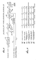
- fault detection circuitry 10 for use in a system for administering a parenteral fluid to the vascular system of a patient 11.
- the system includes a conventional infusion pump 13 and associated pump controlling device 15 for pumping the parenteral fluid through a fluid tube 17 and needle 19 to the patient.
- the pump is preferably of the peristaltic type, which pumps the fluid in a cyclic fashion.
- One such suitable pump and an associated controller for controlling its speed are described in a copending and commonly-assigned application for U.S. Patent, Serial No. 06/281,848, filed July 9, 1981, in the names of Stephen H. O'Leary et al. and entitled "Method and Apparatus for Fluid Flow Control.”
- the pump controlling device 15 outputs a motor step signal for coupling on line 21 to the infusion pump 13.
- the signal is a sequence of pulses, each of which increments the pump by one step, to infuse a predetermined volume of parenteral fluid to the patient 11.
- the parenteral administration system further includes a pressure transducer 23 and an associated amplifier 25 for monitoring the fluid pressure in the fluid tube 17 and producing a corresponding pressure signal for output on line 27.
- the fault detection circuitry 10 evaluates the pressure signal on line 27 to detect certain characteristic patterns indicative of an improper fluid communication between the fluid tube 17 and the patient's vascular system. An alarm 29 is actuated if the circuitry detects such a condition.
- Such fault conditions include infiltrations of the fluid into body tissue other than the patient's vascular system, as well as a complete dislodging of the needle 19 from the patient 11 or a leak or air bubble in the fluid tube. In this way, a proper administration of the parenteral fluid can be ensured without the need for frequent monitoring or testing by hospital personnel.
- the fault detection circuitry 10 includes a low infusion rate venous infiltration detector 31 for detecting infiltrations when the infusion pump 13 is pumping parenteral fluid into the patient's venous system at a relatively low rate, and a high infusion rate venous infiltration detector 33 for detecting infiltrations when the pump is pumping fluid into the venous system at a relatively high rate.
- the fault detection circuitry further includes an arterial infiltration detector 35 for detecting infiltrations when the pump is pumping fluid into the patient's arterial system, and an open line detector 37 for detecting when there is a leak of some kind or an air bubble in the fluid connection between the pump and the patient 11.
- the system further includes a mode switch 39 for indicating whether the system is intended to administer parenteral fluid to the patient's venous system or arterial system.
- the system also includes an infusion rate detector circuit 41, operable whenever the switch indicates that the system is pumping fluid into the patient's venous system to indicate whether the fluid is being pumped at a relatively high rate or a relatively low rate.
- the switch 39 and detector circuit 41 are used to enable operation of the appropriate venous infiltration detector circuit 31 or 33 or arterial infiltration detector circuit 35, depending on the system's operating mode.
- the mode switch 39 is a single-pole, double-throw switch having its middle terminal connected directly to ground and its two remaining terminals connected through separate resistors 43 to a positive voltage.
- the binary signals present on these two terminals are therefore opposite in phase to each other.
- One such signal is defined to be an arterial enable signal and the other is defined to be a venous enable signal.
- the arterial enable signal is coupled on line 45 directly to the arterial infiltration detector circuit 35, and the venous enable signal is coupled on line 47 to the infusion rate detector 41.
- the infusion rate detector circuit relays the venous enable signal to either the low infusion rate venous infiltration detector 31 or the high infusion rate venous infiltration detector 33, depending on the infusion rate being effected by the infusion pump 13.
- the infusion rate detector circuit 41 includes a frequency discriminator 49 for monitoring the motor step signal present on line 21 and producing an output signal having a voltage level generally proportional to the motor step signal's frequency.
- This output signal is coupled on line 51 to the positive input terminal of a comparator 53, which compares it with a selected reference level coupled on its negative input terminal.
- the reference level is supplied on line 55 from the wiper of a potentiometer 57, whose remaining two terminals are connected between ground and a positive supply voltage. If the discriminator output signal exceeds the threshold, indicating that the infusion pump 13 is pumping at a relatively high rate (e.g., above about 40 ml per hour), the comparator outputs a positive voltage level. On the other hand, if the discriminator output signal does not exceed the threshold, indicating that the pump is pumping at a relatively low rate, the comparator outputs a low voltage level signal.
- the signal output by the comparator 53 is coupled on line 59 to a first AND gate 61 for ANDing with the venous enable signal supplied on line 47 from the mode switch 39. This produces a high infusion rate venous enable signal for coupling on line 63 to the high infusion rate venous infiltration detector 33.
- the detector 33 is thereby enabled to detect infiltrations whenever a venous infusion is selected by the mode switch and the infusion rate exceeds the prescribed threshold.
- the signal output by the comparator 53 of the infusion rate detector 41 is also coupled on line 59 to a NOT gate 65, for inversion and coupling in turn on line 67 to a second AND gate 69, where it is ANDed with the same venous enable signal present on line 47.
- the resulting low infusion rate venous enable signal is coupled on line 71 to the low infusion rate venous infiltration detector 31. This detector 31 is thereby enabled whenever a venous infusion is selected by the mode switch 39 and the infusion rate does not exceed the prescribed threshold.
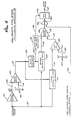
- FIG. 2 there is shown a simplified schematic diagram of the low infusion rate venous infiltration detector 31.
- This circuit monitors the pressure signal supplied on line 27 from the amplifier 25, to detect a characteristic pattern indicative of an occlusion or infiltration of fluid into the patient's body tissue separate from his venous system. When the circuit detects such a condition, it outputs an alarm signal for coupling on line 73 to the alarm 29. Basically, the circuit determines that an occlusion or an infiltration has occurred whenever the pressure signal fails to return to its nominal value within a prescribed time duration following each of the successive pumping pulses of the infusion pump 13.
- the low infusion rate venous infiltration detector 31 includes a 0.1 Hz high-pass filter 75 for filtering the pressure signal supplied on line 27, to produce a filtered pressure signal for output on line 77.
- the pressure signal which is depicted in FIG. 3(c), normally includes a series of positive pressure pulses, each with an exponentially-decaying tail, as a result of the successive motor steps of the infusion pump 13.
- a comparator 79 compares the filtered pressure signal with a selected positive voltage threshold supplied on line 81 from the wiper of a potentiometer 83.
- the other two terminals of the potentiometer are connected between ground and a positive potential. If the filtered pressure signal has a voltage level exceeding the threshold, the comparator outputs a positive signal on line 85 as shown in FIG. 3(d).
- the threshold is preferably selected to be about 30 percent of the pulse's peak value. Typically, the threshold is about four to six cm H2O.
- the detector 31 further includes a monostable multivibrator or one-shot 87 and a flip-flop 89 for sampling the signal output by the comparator 79 about 0.2 seconds after each pulse of the motor step signal (FIG. 3(a)).
- the motor step signal is supplied on line 21 to the one-shot, which produces a corresponding sequence of pulses, (FIG. 3(b)), each having a dura tion of about 0.2 seconds.
- This one shot signal is coupled on line 91 to the clock input terminal of the flip-flop, which samples the pressure derivative signal at the trailing edge of each pulse. If the comparator output signal is still a positive value at this time, the flip-flop outputs a positive signal as well.
- the signal output by the flip-flop 89 is coupled on line 93 to one input terminal of an AND gate 94, which ANDs the signal with the low infusion rate venous enable signal supplied on line 71. It will be recalled that this enable signal indicates that the parenteral administration system is intended to be administering fluid to the patient's venous system at a relatively low rate. If both inputs to the AND gate are a positive value, it is deduced that an infiltration is occurring and the AND gate outputs a trigger signal for coupling on line 95 to a latch 96, which, in turn, produces an alarm signal for coupling on line 73 to the alarm 29 (FIG. 1).
- the pressure signal (FIG. 3(c)) returns to its nominal value relatively quickly after each pulse of the motor step signal (FIG. 3(a)). As a result, the pressure signal does not exceed the threshold and the comparator output signal (FIG. 3(d)) is at a low level at the successive sample times. The detector circuit 31 therefore does not produce an alarm signal.
- the pressure signal (FIG. 3(e)) has a relatively long decay time. This apparently occurs because of an inability of the body tissue to dissipate rapidly each infusion of parenteral fluid. Because of the long decay time, the comparator output signal (FIG. 3(f)) is still at a high level at the time it is sampled by the flip-flop 89. An alarm signal is therefore produced on line 73.
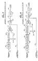
- FIG. 4 there is shown a simplified schematic diagram of the high infusion rate venous infiltration detector 33 of FIG. 1.
- this circuit monitors the pressure signal supplied on line 27 to determine if the pressure in the fluid tube 17 ever increases by more than a selected amount during a predetermined time period. It makes this determination only after the instantaneous rate of change of pressure first exceeds a prescribed level, e.g., 30 cm H2O per second. A positive pressure slope less than this lower threshold can occur during normal situations. A positive pressure slope greater than about 250 cm H2O per second can indicate a downstream occlusion, but is treated by the detector circuit as though it were an infiltration.
- a prescribed level e.g. 30 cm H2O per second.
- the detector circuit samples the pressure signal immediately and again approximately four seconds later. If the second sample exceeds the first by more than a prescribed amount, e.g., 75 cm H2O it is deduced that an infiltration is occurring. An alarm signal is then output on line 97 for coupling to the alarm 29 (FIG. 1).
- the detector circuit 33 of FIG. 4 is suitable for use in detecting infiltrations when the parenteral administration system is administering fluids at rates above about 40 ml per hour.
- the low infusion rate venous infiltration detector 31 of FIG. 2 could also function properly at such infusion rates, but would ordinarily require the momentary disabling of the infusion pump 13 each time it seeks to detect an infiltration. This is because the successive pulses of the infusion pump would then be occurring less than 0.2 seconds apart, which is the nominal sample delay time required by the circuit.
- the high infusion rate venous infiltration detector 33 includes a differentiator 99 for producing a pressure derivative signal, along with a comparator 103 for comparing the pressure derivative signal with a threshold corresponding to 30 cm H2O per second.
- the pressure signal is input to the differentiator on line 27, and the pressure derivative signal is output by the differentiator on line 105 for coupling to the comparator's positive input terminal.
- the comparator's negative input terminal is coupled on line 111 to the wiper of a potentiometer 113.
- the remaining two terminals of the potentiometer are connected to ground and a positive supply voltage, so the voltage present at the wiper of the potentiometer represents a selected positive voltage threshold.
- the comparator produces a positive-valued trigger signal whenever the pressure derivative signal exceeds the threshold.
- the detector circuit 33 of FIG. 4 further includes first and second sample and hold circuits 121 and 123 and a four second monostable multivibrator or one-shot 125.
- the trigger signal produced by the comparator 103 is coupled on line 117 to both the first sample and hold circuit and the one-shot.
- the first sample and hold circuit samples the pressure signal supplied on line 27 and the one-shot simultaneously initiates a four second output pulse that is in a low state.
- the one-shot output signal is coupled on line 129 to the second sample and hold circuit, whereupon four seconds later it likewise samples the pressure signal.
- the signal output by the first sample and hold circuit 121 is coupled on line 131 to a summer 133, for summing with a selected positive voltage level supplied on line 135 from a potentiometer 137. This voltage level represents the minimum amount by which the pressure signal must increase during a four second period for an infiltration to be detected.
- a comparator 139 compares the summer output signal with the signal output by the second sample and hold circuit 123.
- the summer output signal is coupled on line 141 to the comparator's negative input terminal, and the second sample and hold circuit output signal is coupled on line 143 to the comparator's positive input terminal. If the sample and hold signal exceeds the summer signal, it is deduced that the pressure in the fluid tube 17 has increased by more than the prescribed amount (75 cm H2O) during the preceeding four second period and that an infiltration has therefore occurred.
- This signal output by the comparator 139 is coupled on line 145 to an AND gate 147, for ANDing with the high infusion rate venous enable signal supplied on line 63 from the infusion rate detector circuit 41 (FIG. 1). If both AND gate input signals are high, the AND gate produces a high signal for coupling on line 153 to the data input terminal of a flip-flop 155.
- a clock pulse signal for clocking the flip-flop occurs shortly after the end of the four second period, at which time the comparator and AND gate output signals have stabilized.
- This clock pulse signal which is coupled to the flip-flop's clock terminal on line 149, is produced by a clock pulse one-shot 151 in response to the one-shot pulse supplied on line 129 from the four second one-shot 125.
- the flip-flop in turn produces the alarm signal for output on line 97.
- FIG. 5 there is shown a simplified schematic diagram of one embodiment of the arterial infiltration detector 35 of FIG. 1.
- the circuit compares the mean pressure signal, which should correspond to the patient's mean arterial pressure, to a prescribed positive threshold, preferably about 60 cm of water, and outputs an alarm signal on line 157 whenever the signal drops below the threshold.
- the arterial infiltration detector 35 of FIG. 5 includes a 0.1 Hz low-pass filter 159 and a comparator 161.
- the filter filters the pressure signal supplied on line 27 to produce a mean arterial pressure signal for coupling on line 163 to the comparator's negative input terminal.
- the prescribed positive threshold is coupled to the comparator's positive input terminal on line 165 from the wiper of a potentiometer 167.
- the mean arterial pressure signal will exceed the threshold selected by the potentiometer and the comparator will output a signal having a negative level.
- the mean arterial pressure signal will not exceed the threshold and the comparator will output a signal having a positive level.
- a bandwidth of about 0.1 Hz is preferred for the low-pass filter, to substantially remove the effects of the patient's heartbeats.
- the signal output by the comparator 161 is coupled on line 169 to an AND gate 171, for ANDing with the arterial enable signal supplied on line 45. If both signals are at a positive level, then the AND gate likewise outputs a positive level signal.
- This AND gate output signal is coupled on line 173 to a latch 175, which produces the alarm signal for output on line 157.
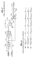
- FIG. 6 there is shown a simplified schematic diagram of an alternative embodiment of the arterial infiltration detector 35 of FIG. 1.
- infiltrations into the patient's body tissue separate from his arterial system are detected by monitoring the pressure signal to detect dropouts in the pressure variations caused by the patient's heartbeat.
- the arterial infiltration detector 35 of FIG. 6 includes a 0.1 Hz high-pass filter 177, a level detector with hysteresis 179, a frequency discriminator 181 and a comparator 183.
- the high-pass filter filters the pressure signal supplied on line 27 to remove its dc level and pass only the successive pulses representative of the patient's heartbeats.
- the heartbeat pulses are present in the pressure signal whenever the fluid tube 17 and the needle 19 (FIG. 1) are coupled directly to the patient's arterial system.
- the high-pass filtered signal is coupled on line 185 to the level detector, which converts the signal to a corresponding pulse sequence signal.
- the level detector detects only pulses having a magnitude of at least about 15 cm H2O.
- the pulse sequence produced by the level detector is coupled on line 185 to the frequency discriminator, which produces an output signal having a level proportional to the frequency of its input signal.
- the heartbeats will be represented in the pressure signal and the frequency discriminator 181 will output a relatively high voltage level signal.
- the heartbeats will not be represented in the pressure signal and the frequency discriminator will output a relatively low level signal.
- the discriminator output signal is coupled on line 187 to the negative input terminal of the comparator 183, which compares it with a selected positive reference level supplied to its positive input terminal on line 189 from a potentiometer 191.
- a selected positive reference level supplied to its positive input terminal on line 189 from a potentiometer 191.
- the comparator outputs a positive voltage level.
- the reference level preferably corresponds to a pulse frequency of about 15 beats per minute.
- the signal output by the comparator 183 is coupled on line 193 to an AND gate 195, where it is ANDed with the arterial enable signal supplied on line 45. If both signals are at a positive level, it is deduced that an arterial infiltration has occurred and the AND gate outputs a corresponding signal for coupling on line 197 to a latch 199. The latch, in turn, outputs the alarm signal for coupling on line 157 to the alarm 29 (FIG. 1).
- FIG. 7 A simplified schematic diagram of the open line detector circuit 37 is depicted in FIG. 7. This circuit monitors the pressure signal supplied on line 27 to detect a fluid leakage, i.e., an open line or an air bubble in the fluid tube 17 between the infusion pump 13 and the patient 11. If the circuit detects such a condition, it outputs an alarm signal for coupling on line 201 to the alarm 29.
- a fluid leakage i.e., an open line or an air bubble in the fluid tube 17 between the infusion pump 13 and the patient 11. If the circuit detects such a condition, it outputs an alarm signal for coupling on line 201 to the alarm 29.
- the pressure signal (FIG. 8(b)) reflects an overdamped or critically damped condition.
- the signal includes a positive pressure pulse immediately following each pulse of the motor step signal (FIG. 8(a)), with each pulse having an exponentially-decaying tail as the patient's vein or artery carries away the small volume of fluid being infused.
- the pressure signal (FIG. 8(c)) reflects an underdamped condition.
- Each pulse of the motor step signal results in an initial increase in fluid pressure, followed immediately thereafter by a momentary decrease in pressure to a level less than the level before the pulse occurred.
- the open line detector 37 detects the occurrence of an open line condition by detecting an underdamped characteristic in the pressure signal, i.e., an overshoot or ringing in the pressure signal following each pulse of the motor step signal. More particularly, the open line detector includes a 3 Hz high-pass filter 203 and a positive peak detector and hold circuit 205.
- the high-pass filter filters the pressure signal supplied on line 27, to remove its dc level but pass the frequencies associated with the successive steps of the infusion pump 13.
- the filtered signal is coupled on line 209 to the peak detector and hold circuit, which outputs a level equal to the signal's positive peak.
- the peak detector circuit which is reset by each pulse in the motor step signal supplied on line 21, can include for example, a series-connected diode followed by a capacitor to ground.
- the signal output by the positive peak detector and hold circuit 205 is coupled on line 211 to an amplifier 213 for amplification by a prescribed fractional amount, e.g., negative two-thirds.
- This amplified signal serves as a threshold to which the high-pass filtered pressure signal is compared in a comparator 215. If the filtered signal is ever more negative than the threshold, it is deduced that there is substantial ringing occurring in the pressure signal and that an open line condition is therefore present.
- the signal output by the amplifier 213 is coupled on line 217 to the comparator's positive input terminal and the high-pass filtered pressure signal is coupled on line 209 to the compara tor's negative input terminal.
- the resulting comparator output signal is coupled on line 219 to a latch 221, which produces the alarm signal for coupling on line 201 to the alarm 29.
- the alarm 29 is responsive to any of the four alarm signals coupled to it on lines 73, 97, 157 and 201 from the fault detection circuitry 10. It includes a four-input OR gate that OR's together the four signals and actuates a visual or audible indicator whenever any of the signals is high. It further includes a switch for use in selectively clearing the latches or flip-flops at the output stage of each detector in the fault detection circuitry.
- the present invention provides an improved apparatus and related method for detecting fault conditions such as an infiltration or an open line in a parenteral administration system.
- the apparatus is particularly adapted for use with a system of the type that includes a pulsing infusion pump for incrementally pumping a parenteral fluid through a fluid tube and needle to a patient's vascular system.
- the apparatus monitors the pressure in the fluid tube to detect characteristic patterns indicative of infiltrations of the fluid into the patient's body tissue separate from either his venous system or arterial system, as well as an open line or air bubble in the fluid coupling between the infusion pump and the patient.
- fault detection circuitry 10 and the infusion rate detector 41 described above can be implemented in both hard nonethelessware and software.
Priority Applications (1)
| Application Number | Priority Date | Filing Date | Title |
|---|---|---|---|
| EP19890105436 EP0328162B1 (de) | 1983-04-11 | 1984-04-10 | Überwachungsgerät für parentale Infusionen und Verfahren zur Überwachung eines eine Flüssigkeit paranteral zuführenden Systems |
Applications Claiming Priority (3)
| Application Number | Priority Date | Filing Date | Title |
|---|---|---|---|
| US483903 | 1983-04-11 | ||
| US06/483,903 US4534756A (en) | 1983-04-11 | 1983-04-11 | Fault detection apparatus and method for parenteral infusion system |
| EP19890105436 EP0328162B1 (de) | 1983-04-11 | 1984-04-10 | Überwachungsgerät für parentale Infusionen und Verfahren zur Überwachung eines eine Flüssigkeit paranteral zuführenden Systems |
Related Parent Applications (1)
| Application Number | Title | Priority Date | Filing Date |
|---|---|---|---|
| EP84103975.3 Division | 1984-04-10 |
Publications (3)
| Publication Number | Publication Date |
|---|---|
| EP0328162A2 true EP0328162A2 (de) | 1989-08-16 |
| EP0328162A3 EP0328162A3 (en) | 1989-10-25 |
| EP0328162B1 EP0328162B1 (de) | 1993-02-10 |
Family
ID=26120015
Family Applications (1)
| Application Number | Title | Priority Date | Filing Date |
|---|---|---|---|
| EP19890105436 Expired - Lifetime EP0328162B1 (de) | 1983-04-11 | 1984-04-10 | Überwachungsgerät für parentale Infusionen und Verfahren zur Überwachung eines eine Flüssigkeit paranteral zuführenden Systems |
Country Status (1)
| Country | Link |
|---|---|
| EP (1) | EP0328162B1 (de) |
Cited By (27)
| Publication number | Priority date | Publication date | Assignee | Title |
|---|---|---|---|---|
| US5059171A (en) * | 1990-06-21 | 1991-10-22 | Boc Health Care, Inc. | Bubble detection system |
| WO1997010013A1 (en) * | 1995-09-12 | 1997-03-20 | Gambro Ab | Method and arrangement for detecting the condition of a blood vessel access |
| US5695473A (en) * | 1994-07-27 | 1997-12-09 | Sims Deltec, Inc. | Occlusion detection system for an infusion pump |
| WO1998020918A1 (en) * | 1996-11-13 | 1998-05-22 | Cobe Laboratories, Inc. | Method and apparatus for occlusion monitoring using pressure waveform analysis |
| DE19734002C1 (de) * | 1997-08-06 | 1998-09-17 | Fresenius Medical Care De Gmbh | Verfahren zur Überwachung eines Gefäßzuganges während einer Dialysebehandlung und Vorrichtung zur Dialysebehandlung mit einer Einrichtung zur Überwachung eines Gefäßzuganges |
| DE19739099C1 (de) * | 1997-09-06 | 1999-01-28 | Fresenius Medical Care De Gmbh | Verfahren zur Überwachung eines Gefäßzuganges während einer extrakorporalen Blutbehandlung und Vorrichtung zur extrakorporalen Blutbehandlung mit einer Einrichtung zur Überwachung eines Gefäßzuganges |
| US7052480B2 (en) | 2002-04-10 | 2006-05-30 | Baxter International Inc. | Access disconnection systems and methods |
| WO2008121581A1 (en) * | 2007-03-30 | 2008-10-09 | Medtronic, Inc. | Catheter malfunction determinations using physiologic pressure |
| EP2030643A1 (de) * | 2006-04-06 | 2009-03-04 | Medtronic, Inc. | Systeme und Verfahren zur Erkennung von Katheter-Fehlfunktionen per Druckmessung |
| WO2009036866A2 (de) * | 2007-09-18 | 2009-03-26 | Fresenius Medical Care Deutschland Gmbh | Verfahren zur überprüfung und/oder überwachung der korrekten funktion einer zugabevorrichtung |
| WO2010046728A1 (en) * | 2008-10-22 | 2010-04-29 | Debiotech S.A. | Mems fluid pump with integrated pressure sensor for dysfunction detection |
| US20100137777A1 (en) * | 2007-05-04 | 2010-06-03 | Pascal Kopperschmidt | Method and device for monitoring a blood treatment unit of an extracorporeal blood treatment device |
| DE102009007806A1 (de) * | 2009-02-06 | 2010-08-12 | Fresenius Medical Care Deutschland Gmbh | Vorrichtung und Verfahren zur Schwingungsanregung wenigstens eines Abschnitts einer Gefäßzugangseinrichtung zu deren Überwachung |
| WO2013002846A1 (en) * | 2011-06-27 | 2013-01-03 | Medtronic, Inc. | Devices and methods for detecting catheter complications |
| CN103727021A (zh) * | 2008-10-22 | 2014-04-16 | 生物技术公司 | 用于检测输注组件中的至少一个功能异常的方法 |
| EP2519276B1 (de) | 2009-12-28 | 2015-03-18 | Gambro Lundia AB | Steuerung eines geräts für den flüssigkeitstransfer zu und/oder von einer person |
| US9138536B2 (en) | 2008-04-01 | 2015-09-22 | Gambro Lundia Ab | Apparatus and a method for monitoring a vascular access |
| US9612182B2 (en) | 2009-12-28 | 2017-04-04 | Gambro Lundia Ab | Method and device for detecting a fault condition |
| US9632018B2 (en) | 2009-12-28 | 2017-04-25 | Gambro Lundia Ab | Method and device for monitoring the integrity of a connection system |
| US9740829B2 (en) | 2006-08-03 | 2017-08-22 | Smiths Medical Asd, Inc. | Interface for medical infusion pump |
| US10155082B2 (en) | 2002-04-10 | 2018-12-18 | Baxter International Inc. | Enhanced signal detection for access disconnection systems |
| US10220132B2 (en) | 2014-12-19 | 2019-03-05 | Fenwal, Inc. | Biological fluid flow control apparatus and method |
| US10357620B2 (en) | 2003-10-02 | 2019-07-23 | Medtronic, Inc. | Determining catheter status |
| US10437963B2 (en) | 2006-08-03 | 2019-10-08 | Smiths Medical Asd, Inc. | Interface for medical infusion pump |
| US10682460B2 (en) | 2013-01-28 | 2020-06-16 | Smiths Medical Asd, Inc. | Medication safety devices and methods |
| US10726100B2 (en) | 2008-05-02 | 2020-07-28 | Tandem Diabetes Care, Inc. | Display for pump |
| US11077240B2 (en) | 2015-06-25 | 2021-08-03 | Gambro Lundia Ab | Detection of a disruption of a fluid connection between two fluid containing systems |
Families Citing this family (12)
| Publication number | Priority date | Publication date | Assignee | Title |
|---|---|---|---|---|
| US6241704B1 (en) | 1901-11-22 | 2001-06-05 | Sims Deltec, Inc. | Drug pump systems and methods |
| US6077055A (en) * | 1998-12-03 | 2000-06-20 | Sims Deltec, Inc. | Pump system including cassette sensor and occlusion sensor |
| US8504179B2 (en) | 2002-02-28 | 2013-08-06 | Smiths Medical Asd, Inc. | Programmable medical infusion pump |
| US8250483B2 (en) | 2002-02-28 | 2012-08-21 | Smiths Medical Asd, Inc. | Programmable medical infusion pump displaying a banner |
| US20040254513A1 (en) | 2002-04-10 | 2004-12-16 | Sherwin Shang | Conductive polymer materials and applications thereof including monitoring and providing effective therapy |
| US9033920B2 (en) | 2003-10-02 | 2015-05-19 | Medtronic, Inc. | Determining catheter status |
| US7320676B2 (en) | 2003-10-02 | 2008-01-22 | Medtronic, Inc. | Pressure sensing in implantable medical devices |
| US8029454B2 (en) | 2003-11-05 | 2011-10-04 | Baxter International Inc. | High convection home hemodialysis/hemofiltration and sorbent system |
| US8954336B2 (en) | 2004-02-23 | 2015-02-10 | Smiths Medical Asd, Inc. | Server for medical device |
| US8858526B2 (en) | 2006-08-03 | 2014-10-14 | Smiths Medical Asd, Inc. | Interface for medical infusion pump |
| US8435206B2 (en) | 2006-08-03 | 2013-05-07 | Smiths Medical Asd, Inc. | Interface for medical infusion pump |
| US8114043B2 (en) | 2008-07-25 | 2012-02-14 | Baxter International Inc. | Electromagnetic induction access disconnect sensor |
Citations (4)
| Publication number | Priority date | Publication date | Assignee | Title |
|---|---|---|---|---|
| FR2091101A5 (de) * | 1970-05-04 | 1972-01-14 | Danske Sukkerfab | |
| US3690318A (en) * | 1970-04-16 | 1972-09-12 | Bourns Inc | Apparatus for parenteral fluid infusion provided with variable flow control means |
| US4392847A (en) * | 1979-01-08 | 1983-07-12 | Whitney Douglass G | Injection and monitoring system |
| EP0096849A2 (de) * | 1982-06-11 | 1983-12-28 | Ivac Corporation | Infusionssystem mit Druckkontrolle |
-
1984
- 1984-04-10 EP EP19890105436 patent/EP0328162B1/de not_active Expired - Lifetime
Patent Citations (4)
| Publication number | Priority date | Publication date | Assignee | Title |
|---|---|---|---|---|
| US3690318A (en) * | 1970-04-16 | 1972-09-12 | Bourns Inc | Apparatus for parenteral fluid infusion provided with variable flow control means |
| FR2091101A5 (de) * | 1970-05-04 | 1972-01-14 | Danske Sukkerfab | |
| US4392847A (en) * | 1979-01-08 | 1983-07-12 | Whitney Douglass G | Injection and monitoring system |
| EP0096849A2 (de) * | 1982-06-11 | 1983-12-28 | Ivac Corporation | Infusionssystem mit Druckkontrolle |
Cited By (48)
| Publication number | Priority date | Publication date | Assignee | Title |
|---|---|---|---|---|
| EP0462405A1 (de) * | 1990-06-21 | 1991-12-27 | The Boc Group, Inc. | Luftblasendetektor |
| US5059171A (en) * | 1990-06-21 | 1991-10-22 | Boc Health Care, Inc. | Bubble detection system |
| US5935106A (en) * | 1994-07-27 | 1999-08-10 | Sims Deltec, Inc. | Occlusion detection system for an infusion pump |
| US5695473A (en) * | 1994-07-27 | 1997-12-09 | Sims Deltec, Inc. | Occlusion detection system for an infusion pump |
| WO1997010013A1 (en) * | 1995-09-12 | 1997-03-20 | Gambro Ab | Method and arrangement for detecting the condition of a blood vessel access |
| US6090048A (en) * | 1995-09-12 | 2000-07-18 | Gambro Ab | Method and arrangement for detecting the condition of a blood vessel access |
| US5906589A (en) * | 1996-11-13 | 1999-05-25 | Cobe Laboratories, Inc. | Method and apparatus for occlusion monitoring using pressure waveform analysis |
| WO1998020918A1 (en) * | 1996-11-13 | 1998-05-22 | Cobe Laboratories, Inc. | Method and apparatus for occlusion monitoring using pressure waveform analysis |
| US6077443A (en) * | 1997-08-06 | 2000-06-20 | Fresenius Medical Care Deutschland Gmbh | Method and device for monitoring a vascular access during a dialysis treatment |
| DE19734002C1 (de) * | 1997-08-06 | 1998-09-17 | Fresenius Medical Care De Gmbh | Verfahren zur Überwachung eines Gefäßzuganges während einer Dialysebehandlung und Vorrichtung zur Dialysebehandlung mit einer Einrichtung zur Überwachung eines Gefäßzuganges |
| DE19739099C1 (de) * | 1997-09-06 | 1999-01-28 | Fresenius Medical Care De Gmbh | Verfahren zur Überwachung eines Gefäßzuganges während einer extrakorporalen Blutbehandlung und Vorrichtung zur extrakorporalen Blutbehandlung mit einer Einrichtung zur Überwachung eines Gefäßzuganges |
| WO1999012588A1 (de) | 1997-09-06 | 1999-03-18 | Fresenius Medical Care Deutschland Gmbh | Verfahren und vorrichtung zur überwachung eines gefässzuganges während einer extrakorporalen blutbehandlung |
| US7052480B2 (en) | 2002-04-10 | 2006-05-30 | Baxter International Inc. | Access disconnection systems and methods |
| US10155082B2 (en) | 2002-04-10 | 2018-12-18 | Baxter International Inc. | Enhanced signal detection for access disconnection systems |
| US10357620B2 (en) | 2003-10-02 | 2019-07-23 | Medtronic, Inc. | Determining catheter status |
| US8317770B2 (en) | 2006-04-06 | 2012-11-27 | Medtronic, Inc. | Systems and methods of identifying catheter malfunctions using pressure sensing |
| EP2030643A1 (de) * | 2006-04-06 | 2009-03-04 | Medtronic, Inc. | Systeme und Verfahren zur Erkennung von Katheter-Fehlfunktionen per Druckmessung |
| US10255408B2 (en) | 2006-08-03 | 2019-04-09 | Smiths Medical Asd, Inc. | Interface for medical infusion pump |
| US10437963B2 (en) | 2006-08-03 | 2019-10-08 | Smiths Medical Asd, Inc. | Interface for medical infusion pump |
| US9740829B2 (en) | 2006-08-03 | 2017-08-22 | Smiths Medical Asd, Inc. | Interface for medical infusion pump |
| US8323244B2 (en) | 2007-03-30 | 2012-12-04 | Medtronic, Inc. | Catheter malfunction determinations using physiologic pressure |
| WO2008121581A1 (en) * | 2007-03-30 | 2008-10-09 | Medtronic, Inc. | Catheter malfunction determinations using physiologic pressure |
| US8574183B2 (en) * | 2007-05-04 | 2013-11-05 | Fresenius Medical Care Deutschland Gmbh | Method and device for monitoring a blood treatment unit of an extracorporeal blood treatment device |
| US20100137777A1 (en) * | 2007-05-04 | 2010-06-03 | Pascal Kopperschmidt | Method and device for monitoring a blood treatment unit of an extracorporeal blood treatment device |
| US20100204633A1 (en) * | 2007-09-18 | 2010-08-12 | Pascal Kopperschmidt | Method for verifying and/or monitoring the correct function of a supply device |
| US8715215B2 (en) | 2007-09-18 | 2014-05-06 | Fresenius Medical Care Deutschland Gmbh | Method for verifying and/or monitoring the correct function of a supply device |
| WO2009036866A3 (de) * | 2007-09-18 | 2009-07-16 | Fresenius Medical Care De Gmbh | Verfahren zur überprüfung und/oder überwachung der korrekten funktion einer zugabevorrichtung |
| WO2009036866A2 (de) * | 2007-09-18 | 2009-03-26 | Fresenius Medical Care Deutschland Gmbh | Verfahren zur überprüfung und/oder überwachung der korrekten funktion einer zugabevorrichtung |
| US9138536B2 (en) | 2008-04-01 | 2015-09-22 | Gambro Lundia Ab | Apparatus and a method for monitoring a vascular access |
| US10726100B2 (en) | 2008-05-02 | 2020-07-28 | Tandem Diabetes Care, Inc. | Display for pump |
| US11488549B2 (en) | 2008-05-02 | 2022-11-01 | Tandem Diabetes Care, Inc. | Display for pump |
| US11580918B2 (en) | 2008-05-02 | 2023-02-14 | Tandem Diabetes Care, Inc. | Display for pump |
| RU2484851C2 (ru) * | 2008-10-22 | 2013-06-20 | Дебиотех С.А. | Жидкостный насос, выполненный в виде мэмс, с встроенным датчиком давления для обнаружения нарушений функционирования |
| WO2010046728A1 (en) * | 2008-10-22 | 2010-04-29 | Debiotech S.A. | Mems fluid pump with integrated pressure sensor for dysfunction detection |
| US9192720B2 (en) | 2008-10-22 | 2015-11-24 | Debiotech S.A. | MEMS fluid pump with integrated pressure sensor for dysfunction detection |
| CN103727021A (zh) * | 2008-10-22 | 2014-04-16 | 生物技术公司 | 用于检测输注组件中的至少一个功能异常的方法 |
| DE102009007806B4 (de) * | 2009-02-06 | 2014-06-05 | Fresenius Medical Care Deutschland Gmbh | Vorrichtung zur Schwingungsanregung wenigstens eines Abschnitts einer Gefäßzugangseinrichtung zu deren Überwachung |
| US9782532B2 (en) | 2009-02-06 | 2017-10-10 | Fresenius Medical Care Deutschland Gmbh | Apparatus and method for the vibratory stimulation of at least one portion of a vascular access device for its monitoring |
| US10098999B2 (en) | 2009-02-06 | 2018-10-16 | Fresenius Medical Care Deutschland Gmbh | Apparatus and method for the vibratory stimulation of at least one portion of a vascular access device for its monitoring |
| DE102009007806A1 (de) * | 2009-02-06 | 2010-08-12 | Fresenius Medical Care Deutschland Gmbh | Vorrichtung und Verfahren zur Schwingungsanregung wenigstens eines Abschnitts einer Gefäßzugangseinrichtung zu deren Überwachung |
| EP2519276B1 (de) | 2009-12-28 | 2015-03-18 | Gambro Lundia AB | Steuerung eines geräts für den flüssigkeitstransfer zu und/oder von einer person |
| US9632018B2 (en) | 2009-12-28 | 2017-04-25 | Gambro Lundia Ab | Method and device for monitoring the integrity of a connection system |
| US9612182B2 (en) | 2009-12-28 | 2017-04-04 | Gambro Lundia Ab | Method and device for detecting a fault condition |
| WO2013002846A1 (en) * | 2011-06-27 | 2013-01-03 | Medtronic, Inc. | Devices and methods for detecting catheter complications |
| US10682460B2 (en) | 2013-01-28 | 2020-06-16 | Smiths Medical Asd, Inc. | Medication safety devices and methods |
| US10881784B2 (en) | 2013-01-28 | 2021-01-05 | Smiths Medical Asd, Inc. | Medication safety devices and methods |
| US10220132B2 (en) | 2014-12-19 | 2019-03-05 | Fenwal, Inc. | Biological fluid flow control apparatus and method |
| US11077240B2 (en) | 2015-06-25 | 2021-08-03 | Gambro Lundia Ab | Detection of a disruption of a fluid connection between two fluid containing systems |
Also Published As
| Publication number | Publication date |
|---|---|
| EP0328162B1 (de) | 1993-02-10 |
| EP0328162A3 (en) | 1989-10-25 |
Similar Documents
| Publication | Publication Date | Title |
|---|---|---|
| US4534756A (en) | Fault detection apparatus and method for parenteral infusion system | |
| EP0328162A2 (de) | Überwachungsgerät für parentale Infusionen und Verfahren zur Überwachung eines eine Flüssigkeit paranteral zuführenden Systems | |
| EP0328163A2 (de) | Überwachungsgerät für parenterale Infusion und Verfahren zur Überwachung eines solches Gerätes | |
| JP2699191B2 (ja) | 自動浸潤検知システムおよび方法 | |
| JP3262336B2 (ja) | 血液の化学的性質をモニタする装置 | |
| EP0361793B1 (de) | Ein in-line-Infiltrationsdetektionsgerät und Methode | |
| US4460355A (en) | Fluid pressure monitoring system | |
| US5423743A (en) | Cannula position detection | |
| CA2268176C (en) | Safety monitoring apparatus for a patient care system | |
| US4743228A (en) | Fluid flow monitoring method and system | |
| DE69634546T2 (de) | Methode und vorrichtung zur aufzeichnung des zustandes eines blutgefässzugangs | |
| EP0248633B1 (de) | Feststellung von Durchflussstörungen bei der parenterale Infusion | |
| EP1339315B1 (de) | Gerät für die blutentnahme und infusion mit einem druckregler | |
| CA2551820C (en) | Medication safety enhancement for secondary infusion | |
| US5423746A (en) | Method and apparatus for infiltration detection during administration of intravenous fluids | |
| US6077443A (en) | Method and device for monitoring a vascular access during a dialysis treatment | |
| US7004924B1 (en) | Methods, systems, and kits for the extracorporeal processing of blood | |
| US20090043240A1 (en) | Method and apparatus for blood transport using a pressure controller in measurement of blood characteristics | |
| JP2010502408A (ja) | 体外血液処理における患者への連結特に血管への連結を監視するための装置と方法 | |
| JPH0425023B2 (de) | ||
| JP2005065888A (ja) | 血管アクセス監視方法および医療装置 | |
| JPS6462B2 (de) | ||
| JPS6066756A (ja) | 低流量持続点滴・輸血装置 |
Legal Events
| Date | Code | Title | Description |
|---|---|---|---|
| PUAI | Public reference made under article 153(3) epc to a published international application that has entered the european phase |
Free format text: ORIGINAL CODE: 0009012 |
|
| 17P | Request for examination filed |
Effective date: 19890328 |
|
| AC | Divisional application: reference to earlier application |
Ref document number: 121931 Country of ref document: EP |
|
| AK | Designated contracting states |
Kind code of ref document: A2 Designated state(s): CH DE FR GB LI |
|
| PUAL | Search report despatched |
Free format text: ORIGINAL CODE: 0009013 |
|
| AK | Designated contracting states |
Kind code of ref document: A3 Designated state(s): CH DE FR GB LI |
|
| 17Q | First examination report despatched |
Effective date: 19910128 |
|
| GRAA | (expected) grant |
Free format text: ORIGINAL CODE: 0009210 |
|
| AC | Divisional application: reference to earlier application |
Ref document number: 121931 Country of ref document: EP |
|
| AK | Designated contracting states |
Kind code of ref document: B1 Designated state(s): CH DE FR GB LI |
|
| REF | Corresponds to: |
Ref document number: 3486071 Country of ref document: DE Date of ref document: 19930325 |
|
| ET | Fr: translation filed | ||
| PLBE | No opposition filed within time limit |
Free format text: ORIGINAL CODE: 0009261 |
|
| STAA | Information on the status of an ep patent application or granted ep patent |
Free format text: STATUS: NO OPPOSITION FILED WITHIN TIME LIMIT |
|
| 26N | No opposition filed | ||
| REG | Reference to a national code |
Ref country code: CH Ref legal event code: PFA Free format text: IVAC CORPORATION TRANSFER- IVAC MEDICAL SYSTEMS, INC. |
|
| REG | Reference to a national code |
Ref country code: FR Ref legal event code: CD Ref country code: FR Ref legal event code: CA |
|
| REG | Reference to a national code |
Ref country code: GB Ref legal event code: 732E |
|
| REG | Reference to a national code |
Ref country code: FR Ref legal event code: TP Ref country code: FR Ref legal event code: CD |
|
| REG | Reference to a national code |
Ref country code: CH Ref legal event code: PFA Free format text: IVAC MEDICAL SYSTEMS, INC. TRANSFER- IVAC HOLDINGS, INC. * IVAC HOLDINGS, INC. TRANSFER- ALARIS MEDICAL SYSTEMS, INC. (A DELAWARE CORPORATION) |
|
| REG | Reference to a national code |
Ref country code: GB Ref legal event code: IF02 |
|
| PGFP | Annual fee paid to national office [announced via postgrant information from national office to epo] |
Ref country code: GB Payment date: 20030402 Year of fee payment: 20 |
|
| PGFP | Annual fee paid to national office [announced via postgrant information from national office to epo] |
Ref country code: FR Payment date: 20030418 Year of fee payment: 20 |
|
| PGFP | Annual fee paid to national office [announced via postgrant information from national office to epo] |
Ref country code: CH Payment date: 20030422 Year of fee payment: 20 |
|
| PGFP | Annual fee paid to national office [announced via postgrant information from national office to epo] |
Ref country code: DE Payment date: 20030430 Year of fee payment: 20 |
|
| REG | Reference to a national code |
Ref country code: GB Ref legal event code: 732E |
|
| PG25 | Lapsed in a contracting state [announced via postgrant information from national office to epo] |
Ref country code: LI Free format text: LAPSE BECAUSE OF EXPIRATION OF PROTECTION Effective date: 20040409 Ref country code: GB Free format text: LAPSE BECAUSE OF EXPIRATION OF PROTECTION Effective date: 20040409 Ref country code: CH Free format text: LAPSE BECAUSE OF EXPIRATION OF PROTECTION Effective date: 20040409 |
|
| REG | Reference to a national code |
Ref country code: CH Ref legal event code: PL |
|
| REG | Reference to a national code |
Ref country code: GB Ref legal event code: PE20 |
|
| REG | Reference to a national code |
Ref country code: FR Ref legal event code: TP Ref country code: FR Ref legal event code: CD |