EP0328094B1 - Doublewalled pipe and connection of coaxial doublewalled pipe sections by means of a connection piece consisting of such a doublewalled pipe - Google Patents
Doublewalled pipe and connection of coaxial doublewalled pipe sections by means of a connection piece consisting of such a doublewalled pipe Download PDFInfo
- Publication number
- EP0328094B1 EP0328094B1 EP89102222A EP89102222A EP0328094B1 EP 0328094 B1 EP0328094 B1 EP 0328094B1 EP 89102222 A EP89102222 A EP 89102222A EP 89102222 A EP89102222 A EP 89102222A EP 0328094 B1 EP0328094 B1 EP 0328094B1
- Authority
- EP
- European Patent Office
- Prior art keywords
- tube
- pipe
- double
- tubes
- screws
- Prior art date
- Legal status (The legal status is an assumption and is not a legal conclusion. Google has not performed a legal analysis and makes no representation as to the accuracy of the status listed.)
- Expired - Lifetime
Links
Images

Classifications
-
- F—MECHANICAL ENGINEERING; LIGHTING; HEATING; WEAPONS; BLASTING
- F16—ENGINEERING ELEMENTS AND UNITS; GENERAL MEASURES FOR PRODUCING AND MAINTAINING EFFECTIVE FUNCTIONING OF MACHINES OR INSTALLATIONS; THERMAL INSULATION IN GENERAL
- F16L—PIPES; JOINTS OR FITTINGS FOR PIPES; SUPPORTS FOR PIPES, CABLES OR PROTECTIVE TUBING; MEANS FOR THERMAL INSULATION IN GENERAL
- F16L39/00—Joints or fittings for double-walled or multi-channel pipes or pipe assemblies
- F16L39/005—Joints or fittings for double-walled or multi-channel pipes or pipe assemblies for concentric pipes
-
- F—MECHANICAL ENGINEERING; LIGHTING; HEATING; WEAPONS; BLASTING
- F16—ENGINEERING ELEMENTS AND UNITS; GENERAL MEASURES FOR PRODUCING AND MAINTAINING EFFECTIVE FUNCTIONING OF MACHINES OR INSTALLATIONS; THERMAL INSULATION IN GENERAL
- F16L—PIPES; JOINTS OR FITTINGS FOR PIPES; SUPPORTS FOR PIPES, CABLES OR PROTECTIVE TUBING; MEANS FOR THERMAL INSULATION IN GENERAL
- F16L9/00—Rigid pipes
- F16L9/18—Double-walled pipes; Multi-channel pipes or pipe assemblies
-
- F—MECHANICAL ENGINEERING; LIGHTING; HEATING; WEAPONS; BLASTING
- F23—COMBUSTION APPARATUS; COMBUSTION PROCESSES
- F23J—REMOVAL OR TREATMENT OF COMBUSTION PRODUCTS OR COMBUSTION RESIDUES; FLUES
- F23J2211/00—Flue gas duct systems
- F23J2211/10—Balanced flues (combining air supply and flue gas exhaust)
- F23J2211/101—Balanced flues (combining air supply and flue gas exhaust) with coaxial duct arrangement
Definitions
- a double pipe according to the invention is particularly advantageous as a connecting piece for producing a coaxial connection of any design double pipes of the type mentioned at the beginning.
- These screws and their abutments are advantageously located in a plane that is perpendicular to the base plane of the two inner half-tubes of the connecting piece. If, as mentioned above, the two base planes of the half-pipes of the connecting piece enclose an angle of 80 ° with one another, then these screws are located outside the area of the interlocking edges of these half-pipes running in the base plane of the larger half-pipes and impair in in no way the sealing of the two halves of the connector with respect to each other.
Abstract
Description
Die Erfindung betrifft ein aus geraden koaxialen Rohren unterschiedlichen Durchmessers bestehendes Doppelrohr, das aus zwei sich zu einem Doppelrohr ergänzenden Hälften zusammengesetzt ist, wobei jede Hälfte aus zwei Halbrohren und Grundebenen besteht. Ein derartiges zweiteiliges Doppelrohr ist aus der FR-PS 773 584 (Fig. 18) bekanntgeworden.The invention relates to a double tube consisting of straight coaxial tubes of different diameters, which is composed of two halves which complement one another, each half consisting of two half tubes and base planes. Such a two-part double tube has become known from FR-PS 773 584 (Fig. 18).
Aus Schüssen solcher Doppelrohre zusammengesetzte Doppelrohrleitungen, die aus einem Innenrohr und einem dieses Innenrohr koaxial ummantelnden Außenrohr bestehen, finden beispielsweise bei brennerbeheizten Geräten Verwendung, wobei das Innenrohr der Abgasführung und das Außenrohr der im Gegenstrom erfolgenden Verbrennungsluftzufuhr zum Brenner des Gerätes dient.Double pipes composed of shots of such double pipes, which consist of an inner pipe and an outer pipe that coaxially surrounds this inner pipe, are used, for example, in burner-heated devices, the inner pipe serving for exhaust gas routing and the outer pipe serving for countercurrent combustion air supply to the burner of the device.
Aufgabe der Erfindung ist es, eine einfach gestaltbare und weitgehend dichte Verbindung der beiden Hälften eines solchen Doppelrohres durch eine originelle Gestaltung dieser Hälften zu erzielen, und zwar eine Verbindung, die sich mit geringem Müheaufwand Weitestgehend durch Formschluß herstellen läßt.The object of the invention is to achieve a simple design and largely tight connection of the two halves of such a double tube by an original design of these halves, namely a connection that can be made largely by positive engagement with little effort.
Diese Aufgabe wird erfindungsgemäß dadurch gelöst, daß jede Hälfte des Doppelrohres aus zwei umfangsmäßig gegeneinander versetzten Halbrohren besteht, deren Grundebenen nahezu senkrecht zueinander verlaufen.This object is achieved in that each half of the double tube consists of two circumferentially offset half-tubes, the base planes of which are almost perpendicular to one another.
Die beiden Halbrohre einer einzelnen Hälfte eines solchen Doppelrohres können einfach und zuverlässig miteinander über einen an einen Rand des Halbrohres mit dem kleineren Halbmesser ansetzenden, radial nach außen ragenden Flansch verbunden sein, dessen Breite der Differenz zwischen den Halbmessern der beiden Halbrohre entspricht. Ein solcher Flansch dient der Versteifung des Doppelrohres und der zuverlässigen Fixierung des koaxial innerhalb des Außenrohres angeordneten Innenrohres.The two half-tubes of a single half of such a double tube can be connected to one another simply and reliably via a flange which projects radially outward and adjoins an edge of the half-tube with the smaller half-diameter and whose width corresponds to the difference between the half-blades of the two half-tubes. Such a flange serves to stiffen the double pipe and the reliable Fixation of the inner tube arranged coaxially within the outer tube.
Besonders günstig ist es, wenn auch der gegenüberliegende Rand des Halbrohres mit dem kleineren Halbmesser in dessen Grundebene einen Solchen radial ansetzenden Flansch trägt. Bei dem aus zwei solchen Hälften zusammengesetzten Doppelrohr kommen dann diese Flansche jeweils beider Hälften aneinander zu liegen und es kann zwischen ihnen eine Dichtung angeordnet werden.It is particularly favorable if the opposite edge of the half-pipe with the smaller half-knife also carries such a radially attached flange in its base plane. In the case of the double tube composed of two such halves, these flanges of both halves come to lie against one another and a seal can be arranged between them.
Um eine dichte Verbindung der beiden Hälften des Doppelrohres miteinander zu erzielen, erweist es sich als zweckdienlich, wenn die von den beiden Flanschen bestimmte Grundebene des Halbrohres mit dem kleineren Halbmesser mit der von den beiden Rändern des Halbrohres mit dem größeren Halbmesser bestimmten Grundebene einen Winkel α von etwa 80° einschließt.In order to achieve a tight connection of the two halves of the double tube with one another, it proves to be expedient if the base plane of the half tube with the smaller diameter determined by the two flanges has an angle α with the base plane determined by the two edges of the half tube with the larger diameter of about 80 °.
Von den beiden einander in der Grundebene gegenüberliegenden Rändern des Halbrohres mit dem größeren Halbmesser kann der eine Rand eine Feder und der andere Rand eine zu dieser Feder passende Nut aufweisen. Dadurch ergibt sich eine formschlüssige dichte Verbindung der beiden gemeinsam das Doppelrohr verkörpernden Hälften.Of the two edges of the half-tube with the larger radius that are opposite each other in the basic plane, one edge can have a tongue and the other edge can have a groove matching this tongue. This results in a form-fitting, tight connection of the two halves jointly embodying the double tube.
Ein erfindungsgemäßes Doppelrohr eignet sich mit besonderen Vorteilen als Verbindungsstück zur Herstellung einer koaxialen Verbindung beliebig gestaltbarer Doppelrohre der eingangs bezeichneten Gattung.A double pipe according to the invention is particularly advantageous as a connecting piece for producing a coaxial connection of any design double pipes of the type mentioned at the beginning.
Die Erfindung erstreckt sich deshalb auch auf eine Verbindung koaxialer Doppelrohrschüsse mittels eines aus einem solchen erfindungsgemäßen Doppelrohr bestehenden Verbindungsstückes.The invention therefore also extends to a connection of coaxial double pipe sections by means of a connecting piece consisting of such a double pipe according to the invention.
Soll das erfindungsgemäße Doppelrohr als solches Verbindungsstück Verwendung finden, dann besteht jede seiner beiden Hälften aus einem Halbrohr mit einem dem Innendurchmesser der Außenrohre der zu verbindenden Rohrschüsse entsprechenden Außendurchmesser und aus einem Halbrohr mit einem dem Außendurchmesser der Innenrohre dieser Rohrschüsse entsprechenden Innendurchmesser.If the double pipe according to the invention is to be used as such a connecting piece, then each of its two halves consists of a half pipe with an outer diameter corresponding to the inner diameter of the outer pipes of the pipe sections to be connected and of a half pipe with an inner diameter corresponding to the outer diameter of the inner pipes of these pipe sections.
Eine besonders dichte und zuverlässige Verbindung des aus einem solchen Doppelrohr gebildeten Verbindungsstückes mit den zu verbindenden Doppelrohrschüssen ist darüber hinaus mittels einander diametral gegenüberliegend angeordneter, in der Wandung des Halbrohres mit dem größeren Halbmesser verschraubbarer Schrauben herstellbar, deren Schäfte gegen ein an der Außenseite der Wandung des Halbrohres mit dem kleineren Halbmesser vorgesehenes Widerlager gerichtet sind. Nach Anziehen solcher Schrauben werden die inneren Halbrohre des Verbindungsstückes vorteilhafterweise gegen die Außenseite der anliegenden Wandungen der Innenrohre der beiden Doppelrohrschüsse und gleichzeitig aber auch die äußeren Halbrohre des Verbindungsstückes gegen die Innenwandungen der Außenrohre der beiden zu verbindenden Doppelrohrschüsse gedrückt.A particularly tight and reliable connection of the connecting piece formed from such a double pipe to the double pipe sections to be connected can also be produced by means of diametrically opposed screws which can be screwed into the wall of the half pipe with the larger radius, the shafts of which against an on the outside of the wall of the Half pipe with the smaller radius provided abutment are directed. After tightening such screws, the inner half pipes of the connecting piece are advantageously pressed against the outside of the adjacent walls of the inner pipes of the two double pipe sections and at the same time the outer half pipes of the connecting piece are pressed against the inner walls of the outer pipes of the two double pipe sections to be connected.
Diese Schrauben und ihre Widerlager befinden sich vorteilhafterweise in einer Ebene, die zur Grundebene der beiden inneren Halbrohre des Verbindungsstückes senkrecht verläuft. Wenn nun die beiden Grundebenen der Halbrohre des Verbindungsstückes, wie oben erwähnt, einen Winkel von 80° miteinander einschließen, dann befinden sich diese Schrauben außerhalb des Bereiches der in der Grundebene der größeren Halbrohre verlaufenden ineinandergreifenden Ränder dieser Halbrohre und beeinträchtigen in in keiner Weise die Abdichtung der beiden Hälften des Verbindungsstückes in bezug zueinander.These screws and their abutments are advantageously located in a plane that is perpendicular to the base plane of the two inner half-tubes of the connecting piece. If, as mentioned above, the two base planes of the half-pipes of the connecting piece enclose an angle of 80 ° with one another, then these screws are located outside the area of the interlocking edges of these half-pipes running in the base plane of the larger half-pipes and impair in in no way the sealing of the two halves of the connector with respect to each other.
Zum Ansetzen der Schrauben, die gegebenenfalls als Gewindeschneidschrauben (Blechschrauben) ausgebildet sein können, ist zweckmäßigerweise an der Außenseite des Halbrohres mit dem größeren Halbmesser eine Rille vorgesehen. Es empfiehlt sich, in Längsrichtung der Halbrohre zumindest zwei voneinander distanzierte Schrauben anzuordnen. Man kann dann diese Schrauben jeweils in Nähe der Ränder der Außenrohre der beiden miteinander zu verbindenden Doppelrohrschüssse anbringen und dadurch eine auch axial formschlüssige Verbindung zwischen diesen Rohrschüssen und dem Verbindungsstück herstellen.A groove is expediently provided on the outside of the half-pipe with the larger radius to attach the screws, which can optionally be designed as self-tapping screws (self-tapping screws). It is advisable to arrange at least two screws spaced apart from one another in the longitudinal direction of the half-tubes. You can then attach these screws in each case in the vicinity of the edges of the outer pipes of the two double pipe sections to be connected to one another and thereby also produce an axially positive connection between these pipe sections and the connecting piece.
Ein Ausführungsbeispiel des Erfindungsgegenstandes ist in den Zeichnungen veranschaulicht und nachstehend an Hand dieser Zeichnungen erläutert. Im einzelnen zeigen
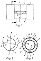
- Fig.1
- eine Seitenansicht einer Verbindung von Doppelrohrschüssen mittels eines als Verbindungsstück dienenden erfindungsgemäßen Doppelrohres,
- Fig.2
- ein einzelnes solches Doppelrohr im Querschnitt,
- Fig.3
- einen Querschnitt nach III-III der Fig.1 und
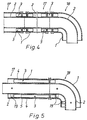
- Fig.4 bis 6
- verschiedene Ausführungsformen solcher Doppelrohrverbindungen in Längsschnitten.
- Fig. 1
- 2 shows a side view of a connection of double pipe sections by means of a double pipe according to the invention serving as a connecting piece,
- Fig. 2
- a single such double tube in cross section,
- Fig. 3
- a cross section according to III-III of Fig.1 and
- Fig. 4 to 6
- different embodiments of such double pipe connections in longitudinal sections.
In allen Zeichnungsfiguren sind die Außenrohre der miteinander zu verbindenden Doppelrohrschüsse mit 1 und deren koaxiale Innenrohre mit 2 bezeichnet.In all drawing figures, the outer tubes of the double tube sections to be connected to one another are designated by 1 and their coaxial inner tubes by 2.
Die beiden allgemein mit 3 bezeichneten Hälften des als Verbindungsstück eingesetzten, erfindungsgemäß ausgebildeten Doppelrohres sind einander gleich und sind paarweise zum Doppelrohr zusammenfügbar.The two halves, generally designated 3, of the double tube used as a connecting piece and designed according to the invention are identical to one another and can be joined together in pairs to form the double tube.
Eine solche Hälfte besteht gemäß Fig.2 jeweils aus einem Halbrohr 4 mit einem dem Innendurchmesser der Außenrohre 1 der zu verbindenden Doppelrohrschüsse entsprechenden Außendurchmesser und aus einem Halbrohr 5 mit einem dem Außendurchmesser deren Innenrohre 2 entsprechenden Innendurchmesser.Such a half consists according to FIG. 2 in each case of a
Diese beiden Halbrohre 4 und 5 einer Hälfte 3 des als Verbindungsstück dienenden Doppelrohres sind miteinander koaxial über einen an einen Rand des Halbrohres 4 mit dem kleineren Halbmesser ansetzenden, radial nach außen ragenden Flansch 6 verbunden, dessen Breite der Differenz zwischen den Halbmessern der beiden Halbrohre 4 und 5, also auch etwa der Differenz zwischen den Halbmessern der Außen- und Innenrohres 1 bzw. 2 der zu verbindenden Doppelrohrschüsse entspricht.These two half-
Auch der andere, gegenüberliegende Rand des Halbrohres 5 mit dem kleineren Halbmesser weist einen solchen radial ansetzenden und nach außen ragenden Flansch 7 derselben Breite auf.The other, opposite edge of the
Wie aus Fig.2 gut ersichtlich ist, schließt die von den beiden Flanschen 6 und 7 des Halbrohres 5 mit dem kleineren Halbmesser bestimmte Grundebene 8 mit der von den beiden Rändern des Halbrohres 4 mit dem größeren Halbmesser bestimmten Grundebene 9 einen winkel α von etwa 80° ein.As can be clearly seen from FIG. 2, the
Von den beiden Rändern des Halbrohres 4 mit dem größeren Halbmesser weist der eine Rand eine Feder 11 und der andere Rand eine zu dieser Feder 11 passende, der formschlüssigen Verbindung der beiden Ränder jeweils zweier Hälften 3 dienende Nut 12 auf.Of the two edges of the half-
Zur Fixierung und Abdichtung der Verbindung der Doppelrohr= schüsse sind einander diametral gegenüberliegend angeordnete, in der Wandung der Halbrohre 4 mit dem größeren Halbmesser verschraubbare Schrauben 14 vorgesehen, deren Schäfte gegen die an der Außenseite der Wandung des Halbrohres 5 mit dem kleineren Halbmesser ausgebildeten Widerlager 15 gerichtet sind.To fix and seal the connection of the double pipe = shots, diametrically opposed
Die Schrauben 14 und ihre Widerlager 15 sind in einer Ebene angeordnet, die zur Grundebene 8 des Halbrohres 5 mit dem kleineren Halbmesser, also zur Ebene der Flanschen 6 und 7, senkrecht verläuft und mit der durch die Ränder des größeren Halbrohres 4 bestimmten Grundebene 9 einen Winkel von etwa 10° einschließt. Dadurch befinden sich diese Schrauben 14 außerhalb des Bereiches der dichtenden, mit Feder 11 und Nut 12 ausgebildeten Ränder der Halbrohre 4 mit dem größeren Halbmesser.The
In dieser Ebene der Schrauben 14 und ihrer Widerlager 15 ist an der Außenseite des Halbrohres 4 mit dem größeren Halbmesser eine aus Fig.1 ersichtliche Rille 13 zum Ansetzen der Schrauben 14 vorgesehen.In this plane of the
Bei der aus Fig.3 ersichtlichen fertigen Verbindung liegen die Flanschen 6 und 7 der beiden Hälften 3 des Verbindungsstückes an einer Dichtung 16 an und schließen diese Dichtung gemeinsam ein. Die Federn 11 und Nuten 12 der Ränder der Halbrohre 4 mit dem größeren Halbmesser greifen dichtend ineinander und durch die gegen das Widerlager 15 drückenden Schrauben 14 werden die Halbrohre 4 mit dem größeren Halbmesser an die Innenseite der Wandung der Außenrohre 1 und die Halbrohre 5 mit dem kleineren Halbmesser an die Außenseite der Wandung der Innenrohre 2 angedrückt. Durch das Anziehen der Schrauben 14 werden also sowohl die beiden Hälften 3 des Verbindungsstückes miteinander als auch dieses Verbindungsstück mit den beiden Rohrschüssen dichtend verbunden.In the finished connection shown in FIG. 3, the
Wie die Fig.1 zeigt, sind jeweils zumindest zwei in der Längsrichtung der Rohre voneinander distanzierte Schrauben 14 vorgesehen, und zwar sind sie vorteilhafterweise in unmittelbarer Nähe der zueinanderweisenden Ränder der beiden Außenrohre 1 der mitteinander zu verbindenden Doppelrohrschüsse angeordnet, um auf diese Weise eine formschlüssige Verbindung dieser Doppelrohrschüsse auch in axialer Richtung zu erzielen.As shown in FIG. 1, at least two
Fig.4 zeigt eine Verbindung zweier Doppelrohrschüsse 17 miteinander und eines Doppelrohrschusses 17 mit einem Doppelrohrkrümmer 18, wobei die Verbindungsstücke aus den Hälften 3 gewissermaßen als Rohrschellen wirksam sind und die Anordnung von Abstandbügeln erübrigen.FIG. 4 shows a connection between two
Fig. 5 und 6 zeigen, daß erfindungsgemäße Verbindungsstücke auch zu einer Teleskopverbindung von Doppelrohrschüssen 17 bzw. 18 mit variabler Distanz der Stirnseiten verwendbar sind.5 and 6 show that connecting pieces according to the invention can also be used for a telescopic connection of
Im Rahmen der Erfindung kann sich eine Doppelrohrleitung - gemäß haben erläuterter Ausführungsbeispiele - aus beliebig gestaltbaren Doppelrohrschüssen und erfindungsgemäß gestalteten als Verbindungsstücke dienenden Doppelrohren zusammensetzen. Man kann aber eine solche Doppelrohrleitung auch durchwegs aus erfindungsgemäß gestalteten Doppelrohren bilden, die auf beliebige Art, z.B. durch Rohrschellen, miteinander verbunden sind.Within the scope of the invention, a double pipeline - according to exemplary embodiments which have been explained - can be composed of arbitrarily designed double pipe sections and double pipes designed according to the invention and serving as connecting pieces. However, one can also consistently form such a double pipeline from double pipes designed according to the invention, which can be used in any way, e.g. connected by pipe clamps.
Claims (11)
- A double tube, which consists of straight coaxial tubes differing in diameter and is composed of two halves, which complement to form a double tube and each of which consists of two half-tubes and base planes, characterized in that each half (3) consists of two half-tubes (4, 5), which are peripherally offset from each other and have base planes (8,9) which are almost at right angles to each other.
- A double tube according to claim 1, characterized in that said two half-tubes (4, 5) of one half (3) are interconnected by a flange (6), which joins one edge of that half-tube (5) which has a smaller radius and said flange radially outwardly in the base plane (8) of said half-tube and has a width that is equal to the difference between the radii of the two half-tubes (4,5).
- A double tube according to claim 2, characterized in that the opposite edge of the half-tube (5) which has a smaller radius also carries such a flange (7), which radially joins said half-tube (5) in its base plane (8).
- A double tube according to claim 3, characterized in that the base plane (8) of the half-tube (5) which has a smaller radius and is determined by the two flanges (6, 7) and includes an angle of about 80° with that base plane (9) which is defined by the two edges of the half-tube (4) which has a larger radius.
- A double tube according to any of claims 2 to 4, characterized in that one of the two opposite edges of the half-tube (4) which has a larger radius is provided with a tongue (11) and the other of said two edges is provided with a groove (12), which fits said tongue (11) for making a positive joint.
- A joint in which two coaxial double tube sections are connected by a connecting member which consists of a double tube according to any of claims 1 to 5, characterized in that each of the two halves (3) of that connecting member consists of a half-tube (4), which has an outside diameter corresponding to the inside diameter of the outer tubes (1) of the tube sections to be connected and of a half-tube (5), which has an inside diameter corresponding to the outside diameter of the inner tubes (2) of said tube sections.
- A joint according to claim 6, characterized by diametrically opposite screws (14), which are adapted to be screwed into the wall of the half-tube (4) which has a larger radius and have shanks which are directed towards an abutment (15) which is provided on the outside surface of the wall of the half-tube (5) which has a smaller radius.
- A joint according to claim 7, characterized in that the screws (14) and the associated abutments (15) are disposed in a plane which is at right angles to the base plane (8) of that half-tube (5) which has a smaller radius.
- A joint according to claim 8, characterized in that the half-tube (4) which has a larger radius is formed with a groove (13), which is engageable by the screws (14) and extends in said plane in which the screws (14) and the associated abutments (15) are disposed.
- A joint according to any of claims 7 to 9, characterized by at least two screws (14) which are spaced apart in the longitudinal direction of the half-tubes (4, 5).
- A joint according to claim 10, characterized in that said screws (14) are disposed close to the edges of the outer tubes (1) of the two double tube sections (17, 18) which are to be connected.
Applications Claiming Priority (2)
| Application Number | Priority Date | Filing Date | Title |
|---|---|---|---|
| AT239/88 | 1988-02-08 | ||
| AT0023988A AT388790B (en) | 1988-02-08 | 1988-02-08 | DOUBLE TUBE AND CONNECTING COAXIAL DOUBLE TUBE SHOOTINGS TO A CONNECTING PIECE CONSISTING OF SUCH A DOUBLE TUBE |
Publications (3)
| Publication Number | Publication Date |
|---|---|
| EP0328094A2 EP0328094A2 (en) | 1989-08-16 |
| EP0328094A3 EP0328094A3 (en) | 1991-07-03 |
| EP0328094B1 true EP0328094B1 (en) | 1993-12-08 |
Family
ID=3485248
Family Applications (1)
| Application Number | Title | Priority Date | Filing Date |
|---|---|---|---|
| EP89102222A Expired - Lifetime EP0328094B1 (en) | 1988-02-08 | 1989-02-08 | Doublewalled pipe and connection of coaxial doublewalled pipe sections by means of a connection piece consisting of such a doublewalled pipe |
Country Status (3)
| Country | Link |
|---|---|
| EP (1) | EP0328094B1 (en) |
| AT (2) | AT388790B (en) |
| DE (2) | DE8901430U1 (en) |
Families Citing this family (3)
| Publication number | Priority date | Publication date | Assignee | Title |
|---|---|---|---|---|
| CA2107562A1 (en) * | 1991-04-04 | 1992-10-05 | Christopher G. Ziu | Elbow fittings for double containment pipe assemblies |
| CN113700946B (en) * | 2021-04-20 | 2023-04-25 | 海洋石油工程(青岛)有限公司 | Pipeline construction method for flare emptying system |
| CN114526380B (en) * | 2022-04-08 | 2023-11-14 | 广东粤亚塑料制品有限公司 | General pipe structure |
Citations (1)
| Publication number | Priority date | Publication date | Assignee | Title |
|---|---|---|---|---|
| FR773584A (en) * | 1934-02-16 | 1934-11-21 | Erbsloeh Julius & August | Tubular body |
Family Cites Families (6)
| Publication number | Priority date | Publication date | Assignee | Title |
|---|---|---|---|---|
| US3088495A (en) * | 1957-12-16 | 1963-05-07 | Flexigrip Inc | Rib and groove fastener structure |
| DE2018977A1 (en) * | 1970-04-21 | 1971-11-04 | Prix Wiehofsky & Drexl | Process for the production of an assemblable ventilation pipe |
| DE2131429C2 (en) * | 1971-06-24 | 1973-04-12 | Prix Bauelemente Wieliofsicy & DrexJ, 8919 Schondorf | PIPE, IN PARTICULAR VENTILATION PIPE |
| GB1422156A (en) * | 1972-02-09 | 1976-01-21 | Boc International Ltd | Vacuum-insulated pipeline assembly |
| FR2350539A1 (en) * | 1976-05-07 | 1977-12-02 | Saunier Duval | CONNECTION ELBOW FOR TWO CONCENTRIC TUBES |
| DE8631085U1 (en) * | 1986-11-20 | 1987-06-25 | Joh. Vaillant Gmbh U. Co, 5630 Remscheid, De |
-
1988
- 1988-02-08 AT AT0023988A patent/AT388790B/en not_active IP Right Cessation
-
1989
- 1989-02-08 AT AT89102222T patent/ATE98348T1/en not_active IP Right Cessation
- 1989-02-08 DE DE8901430U patent/DE8901430U1/de not_active Expired
- 1989-02-08 DE DE89102222T patent/DE58906328D1/en not_active Expired - Fee Related
- 1989-02-08 EP EP89102222A patent/EP0328094B1/en not_active Expired - Lifetime
Patent Citations (1)
| Publication number | Priority date | Publication date | Assignee | Title |
|---|---|---|---|---|
| FR773584A (en) * | 1934-02-16 | 1934-11-21 | Erbsloeh Julius & August | Tubular body |
Also Published As
| Publication number | Publication date |
|---|---|
| DE58906328D1 (en) | 1994-01-20 |
| ATA23988A (en) | 1989-01-15 |
| DE8901430U1 (en) | 1989-08-17 |
| AT388790B (en) | 1989-08-25 |
| ATE98348T1 (en) | 1993-12-15 |
| EP0328094A2 (en) | 1989-08-16 |
| EP0328094A3 (en) | 1991-07-03 |
Similar Documents
| Publication | Publication Date | Title |
|---|---|---|
| DE3047867C2 (en) | Pipe connection | |
| DE19718178C2 (en) | Pipe connection device with a double pipe and method for producing a pipe connection device with a double pipe and exhaust manifold with double pipe for an internal combustion engine | |
| DE3447270C2 (en) | ||
| EP0328094B1 (en) | Doublewalled pipe and connection of coaxial doublewalled pipe sections by means of a connection piece consisting of such a doublewalled pipe | |
| DE7036005U (en) | PIPE COUPLING WITH V-SHAPED FLANGE FOR CONNECTING PIPES OR HOSES. | |
| EP0636827B1 (en) | Pipe profile for exhaust gas systems, especially for condensing boilers | |
| EP0143150B1 (en) | Flange coupling | |
| EP0160890A2 (en) | Smoke conduit affixable to a framework | |
| DE1602262C3 (en) | Method for the production of a pipe branch without welding seams | |
| DE202004017501U1 (en) | Device for connecting two exhaust pipes leading off | |
| DE2734983A1 (en) | Vehicle IC engine exhaust systems - has flexible strip wound into polygonal section spiral sealed along edges by folded seam | |
| DE19523506A1 (en) | Flexible connector for pair of spaced pipes - comprises bellows whose ends are attached to sleeves which fix to pipes by sections having constricted diameter | |
| DE2909923C2 (en) | ||
| DE3518813A1 (en) | FLANGE FOR FASTENING TUBES | |
| DE2135514C3 (en) | Pipe socket for angularly movable pipelines | |
| DE2615272A1 (en) | Pipe connection with short overlap between pipes - has cylindrical clip around joint to allow easy separation even if joint is corroded | |
| EP0024709A1 (en) | Clamp joint with gasket for gas and water pipes | |
| AT94023B (en) | Pipe connection. | |
| DE60315315T2 (en) | BELT, PIPE CONNECTION AND EXHAUST SYSTEM | |
| DE19906174C1 (en) | Seal for valve flaps in motor vehicle exhaust duct has polygonal seals with sliding steel sections reinforcing corners of polygonal section | |
| DE2037898C3 (en) | Flexible connection piece made of textile-reinforced, rubber-like material for expansion joints between pipes with polygonal cross-sections with end flanges | |
| DE3607455A1 (en) | Double pipe bend | |
| WO2023078910A1 (en) | Instrument panel carrier for a motor vehicle | |
| CH504662A (en) | Flat tube and process for its manufacture | |
| CH639183A5 (en) | PIPE CONNECTION. |
Legal Events
| Date | Code | Title | Description |
|---|---|---|---|
| PUAI | Public reference made under article 153(3) epc to a published international application that has entered the european phase |
Free format text: ORIGINAL CODE: 0009012 |
|
| AK | Designated contracting states |
Kind code of ref document: A2 Designated state(s): AT BE CH DE ES FR GB GR IT LI LU NL SE |
|
| PUAL | Search report despatched |
Free format text: ORIGINAL CODE: 0009013 |
|
| AK | Designated contracting states |
Kind code of ref document: A3 Designated state(s): AT BE CH DE ES FR GB GR IT LI LU NL SE |
|
| 17P | Request for examination filed |
Effective date: 19910523 |
|
| 17Q | First examination report despatched |
Effective date: 19920219 |
|
| RAP1 | Party data changed (applicant data changed or rights of an application transferred) |
Owner name: VAILLANT GES.M.B.H Owner name: JOH. VAILLANT GMBH U. CO. Owner name: VAILLANT S.A.R.L Owner name: VAILLANT GMBH Owner name: VAILLANT LTD. Owner name: VAILLANT B.V. Owner name: N.V. VAILLANT S.A. |
|
| RAP3 | Party data changed (applicant data changed or rights of an application transferred) |
Owner name: VAILLANT GES.M.B.H Owner name: VAILLANT S.A.R.L Owner name: N.V. VAILLANT S.A. Owner name: VAILLANT LTD. Owner name: JOH. VAILLANT GMBH U. CO. Owner name: VAILLANT GMBH Owner name: VAILLANT B.V. |
|
| GRAA | (expected) grant |
Free format text: ORIGINAL CODE: 0009210 |
|
| PGFP | Annual fee paid to national office [announced via postgrant information from national office to epo] |
Ref country code: FR Payment date: 19931201 Year of fee payment: 6 |
|
| AK | Designated contracting states |
Kind code of ref document: B1 Designated state(s): AT BE CH DE ES FR GB GR IT LI LU NL SE |
|
| PG25 | Lapsed in a contracting state [announced via postgrant information from national office to epo] |
Ref country code: SE Effective date: 19931208 Ref country code: GR Free format text: LAPSE BECAUSE OF FAILURE TO SUBMIT A TRANSLATION OF THE DESCRIPTION OR TO PAY THE FEE WITHIN THE PRESCRIBED TIME-LIMIT Effective date: 19931208 Ref country code: ES Free format text: THE PATENT HAS BEEN ANNULLED BY A DECISION OF A NATIONAL AUTHORITY Effective date: 19931208 Ref country code: IT Free format text: LAPSE BECAUSE OF FAILURE TO SUBMIT A TRANSLATION OF THE DESCRIPTION OR TO PAY THE FEE WITHIN THE PRE;WARNING: LAPSES OF ITALIAN PATENTS WITH EFFECTIVE DATE BEFORE 2007 MAY HAVE OCCURRED AT ANY TIME BEFORE 2007. THE CORRECT EFFECTIVE DATE MAY BE DIFFERENT FROM THE ONE RECORDED.SCRIBED TIME-LIMIT Effective date: 19931208 |
|
| PGFP | Annual fee paid to national office [announced via postgrant information from national office to epo] |
Ref country code: GB Payment date: 19931208 Year of fee payment: 6 |
|
| REF | Corresponds to: |
Ref document number: 98348 Country of ref document: AT Date of ref document: 19931215 Kind code of ref document: T |
|
| PGFP | Annual fee paid to national office [announced via postgrant information from national office to epo] |
Ref country code: BE Payment date: 19940112 Year of fee payment: 6 |
|
| REF | Corresponds to: |
Ref document number: 58906328 Country of ref document: DE Date of ref document: 19940120 |
|
| PGFP | Annual fee paid to national office [announced via postgrant information from national office to epo] |
Ref country code: AT Payment date: 19940121 Year of fee payment: 6 |
|
| PGFP | Annual fee paid to national office [announced via postgrant information from national office to epo] |
Ref country code: DE Payment date: 19940202 Year of fee payment: 6 |
|
| PGFP | Annual fee paid to national office [announced via postgrant information from national office to epo] |
Ref country code: CH Payment date: 19940203 Year of fee payment: 6 |
|
| PG25 | Lapsed in a contracting state [announced via postgrant information from national office to epo] |
Ref country code: LU Free format text: LAPSE BECAUSE OF NON-PAYMENT OF DUE FEES Effective date: 19940228 |
|
| GBT | Gb: translation of ep patent filed (gb section 77(6)(a)/1977) |
Effective date: 19940203 |
|
| ET | Fr: translation filed | ||
| PLBE | No opposition filed within time limit |
Free format text: ORIGINAL CODE: 0009261 |
|
| STAA | Information on the status of an ep patent application or granted ep patent |
Free format text: STATUS: NO OPPOSITION FILED WITHIN TIME LIMIT |
|
| 26N | No opposition filed | ||
| PG25 | Lapsed in a contracting state [announced via postgrant information from national office to epo] |
Ref country code: GB Effective date: 19950208 Ref country code: AT Effective date: 19950208 |
|
| PG25 | Lapsed in a contracting state [announced via postgrant information from national office to epo] |
Ref country code: CH Effective date: 19950228 Ref country code: LI Effective date: 19950228 Ref country code: BE Effective date: 19950228 |
|
| PGFP | Annual fee paid to national office [announced via postgrant information from national office to epo] |
Ref country code: NL Payment date: 19950228 Year of fee payment: 7 |
|
| BERE | Be: lapsed |
Owner name: N.V. VAILLANT S.A. Effective date: 19950228 |
|
| GBPC | Gb: european patent ceased through non-payment of renewal fee |
Effective date: 19950208 |
|
| PG25 | Lapsed in a contracting state [announced via postgrant information from national office to epo] |
Ref country code: FR Effective date: 19951031 |
|
| PG25 | Lapsed in a contracting state [announced via postgrant information from national office to epo] |
Ref country code: DE Effective date: 19951101 |
|
| REG | Reference to a national code |
Ref country code: FR Ref legal event code: ST |
|
| PG25 | Lapsed in a contracting state [announced via postgrant information from national office to epo] |
Ref country code: NL Effective date: 19960901 |
|
| NLV4 | Nl: lapsed or anulled due to non-payment of the annual fee |
Effective date: 19960901 |