EP0328094A2 - Tuyau à double paroi et raccordement de sections coaxiales de tuyaux à double paroi par une pièce de raccordement composée d'un tel tuyau à double paroi - Google Patents
Tuyau à double paroi et raccordement de sections coaxiales de tuyaux à double paroi par une pièce de raccordement composée d'un tel tuyau à double paroi Download PDFInfo
- Publication number
- EP0328094A2 EP0328094A2 EP19890102222 EP89102222A EP0328094A2 EP 0328094 A2 EP0328094 A2 EP 0328094A2 EP 19890102222 EP19890102222 EP 19890102222 EP 89102222 A EP89102222 A EP 89102222A EP 0328094 A2 EP0328094 A2 EP 0328094A2
- Authority
- EP
- European Patent Office
- Prior art keywords
- pipe
- double
- tubes
- tube
- screws
- Prior art date
- Legal status (The legal status is an assumption and is not a legal conclusion. Google has not performed a legal analysis and makes no representation as to the accuracy of the status listed.)
- Granted
Links
Images

Classifications
-
- F—MECHANICAL ENGINEERING; LIGHTING; HEATING; WEAPONS; BLASTING
- F16—ENGINEERING ELEMENTS AND UNITS; GENERAL MEASURES FOR PRODUCING AND MAINTAINING EFFECTIVE FUNCTIONING OF MACHINES OR INSTALLATIONS; THERMAL INSULATION IN GENERAL
- F16L—PIPES; JOINTS OR FITTINGS FOR PIPES; SUPPORTS FOR PIPES, CABLES OR PROTECTIVE TUBING; MEANS FOR THERMAL INSULATION IN GENERAL
- F16L39/00—Joints or fittings for double-walled or multi-channel pipes or pipe assemblies
- F16L39/005—Joints or fittings for double-walled or multi-channel pipes or pipe assemblies for concentric pipes
-
- F—MECHANICAL ENGINEERING; LIGHTING; HEATING; WEAPONS; BLASTING
- F16—ENGINEERING ELEMENTS AND UNITS; GENERAL MEASURES FOR PRODUCING AND MAINTAINING EFFECTIVE FUNCTIONING OF MACHINES OR INSTALLATIONS; THERMAL INSULATION IN GENERAL
- F16L—PIPES; JOINTS OR FITTINGS FOR PIPES; SUPPORTS FOR PIPES, CABLES OR PROTECTIVE TUBING; MEANS FOR THERMAL INSULATION IN GENERAL
- F16L9/00—Rigid pipes
- F16L9/18—Double-walled pipes; Multi-channel pipes or pipe assemblies
-
- F—MECHANICAL ENGINEERING; LIGHTING; HEATING; WEAPONS; BLASTING
- F23—COMBUSTION APPARATUS; COMBUSTION PROCESSES
- F23J—REMOVAL OR TREATMENT OF COMBUSTION PRODUCTS OR COMBUSTION RESIDUES; FLUES
- F23J2211/00—Flue gas duct systems
- F23J2211/10—Balanced flues (combining air supply and flue gas exhaust)
- F23J2211/101—Balanced flues (combining air supply and flue gas exhaust) with coaxial duct arrangement
Definitions
- the invention relates to a double tube consisting of coaxial tubes of different diameters, which is composed of two halves which complement each other to form a double tube.
- Double pipes composed of shots of such double pipes which consist of an inner pipe and an outer pipe coaxially encasing this inner pipe, are used, for example, in burner-heated devices, the inner pipe serving for exhaust gas routing and the outer pipe serving for countercurrent combustion air supply to the burner of the device.
- the object of the invention is to achieve a simple design and largely tight connection of the two halves of such a double tube by an original design of these halves, namely a connection that can be made largely by positive engagement with little effort.
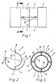
- each half of the double tube consists of two half tubes, the base planes of which are almost perpendicular to one another.
- the two half-tubes of a single half of such a double tube can be connected to one another simply and reliably via a flange which projects radially outwards and which extends to an edge of the half-tube with the smaller half-diameter and whose width corresponds to the difference between the half-blades of the two half-tubes.
- a flange serves to stiffen the double pipe and the reliable Fixation of the inner tube arranged coaxially within the outer tube.
- the opposite edge of the half pipe with the smaller radius also carries such a radially attached flange in its base plane.
- these flanges of both halves come to lie against one another and a seal can be arranged between them.
- the base plane of the half tube with the smaller diameter determined by the two flanges has an angle ⁇ with the base plane determined by the two edges of the half tube with the larger diameter of about 80 °.
- one edge can have a tongue and the other edge can have a groove matching this tongue. This results in a form-fitting, tight connection of the two halves jointly embodying the double tube.
- a double pipe according to the invention is suitable as a connecting piece for producing a coaxial connection of arbitrarily designed double pipes of the type described in the introduction.
- the invention therefore also extends to a connection of coaxial double pipe sections by means of a connecting piece consisting of such a double pipe according to the invention.
- each of its two halves consists of a half pipe with an outer diameter corresponding to the inner diameter of the outer pipes of the pipe sections to be connected and of a half pipe with an inner diameter corresponding to the outer diameter of the inner pipes of these pipe sections.
- a particularly tight and reliable connection of the connecting piece formed from such a double pipe to the double pipe sections to be connected can also be produced by means of diametrically opposed screws which can be screwed into the wall of the half pipe with the larger radius, the shafts of which can be screwed against an on the outside of the wall of the Half pipe with the smaller radius provided abutment are directed.
- the inner half pipes of the connecting piece are advantageously pressed against the outside of the adjacent walls of the inner pipes of the two double pipe sections and at the same time the outer half pipes of the connecting piece are pressed against the inner walls of the outer pipes of the two double pipe sections to be connected.
- These screws and their abutments are advantageously in a plane that is perpendicular to the base plane of the two inner half-tubes of the connecting piece. If, as mentioned above, the two base planes of the half-pipes of the connecting piece enclose an angle of 80 ° with one another, then these screws are located outside the area of the interlocking edges of these half-pipes running in the base plane of the larger half-pipes and impair in in no way the sealing of the two halves of the connector with respect to each other.
- a groove is expediently provided on the outside of the half-tube with the larger radius to attach the screws, which can optionally be designed as self-tapping screws (self-tapping screws). It is advisable to arrange at least two screws spaced apart from one another in the longitudinal direction of the half-tubes. You can then attach these screws in each case near the edges of the outer tubes of the two double tube sections to be connected to one another, thereby producing an axially positive connection between these pipe sections and the connecting piece.
- outer tubes of the double tube sections to be connected to one another are designated by 1 and their coaxial inner tubes by 2.
- the two halves, generally designated 3, of the double tube used as a connecting piece and designed according to the invention are identical to one another and can be joined together in pairs to form the double tube.
- Such a half consists according to FIG. 2 in each case of a half pipe 4 with an outer diameter corresponding to the inner diameter of the outer pipes 1 of the double pipe sections to be connected and of a half pipe 5 with an inner diameter corresponding to the outer diameter of their inner pipes 2.
- the other, opposite edge of the half pipe 5 with the smaller radius also has such a radially starting and outwardly projecting flange 7 of the same width.
- the base plane 8 determined by the two flanges 6 and 7 of the half tube 5 with the smaller radius closes an angle ⁇ of approximately 80 with the base plane 9 determined by the two edges of the half tube 4 with the larger diameter ° a.
- one edge has a tongue 11 and the other edge has a groove 12 that fits this tongue 11 and serves for the positive connection of the two edges of two halves 3.
- diametrically opposed screws 14 are provided in the wall of the half pipes 4 with the larger diameter, the shanks of which are formed against the abutment 15 formed on the outside of the wall of the half pipe 5 with the smaller diameter are directed.
- the screws 14 and their abutments 15 are arranged in a plane which runs perpendicular to the base plane 8 of the half pipe 5 with the smaller radius, i.e. to the plane of the flanges 6 and 7, and with the base plane 9 determined by the edges of the larger half pipe 4 Includes an angle of approximately 10 °. As a result, these screws 14 are located outside the area of the sealing edges of the half-tubes 4 with the larger half-knife, which are formed with tongue 11 and groove 12.
- a groove 13 shown in FIG. 1 is provided on the outside of the half pipe 4 with the larger radius for attaching the screws 14.
- the flanges 6 and 7 of the two halves 3 of the connecting piece lie against a seal 16 and enclose this seal together.
- the springs 11 and grooves 12 of the edges of the half-tubes 4 with the larger half-knife engage in one another in a sealing manner and by means of the screws 14 pressing against the abutment 15, the half-tubes 4 with the larger half-knife are connected to the inside of the wall of the outer tubes 1 and the half-tubes 5 with the smaller radius on the outside of the wall of the inner tubes 2 presses.
- both the two halves 3 of the connecting piece are connected to one another and this connecting piece is sealed to the two pipe sections.
- At least two screws 14 spaced apart in the longitudinal direction of the tubes are provided, and they are advantageously arranged in the immediate vicinity of the mutually facing edges of the two outer tubes 1 of the double tube sections to be connected to one another, in order in this way to provide a positive fit To achieve this double pipe sections also in the axial direction.
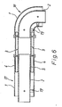
- connecting pieces according to the invention can also be used for a telescopic connection of double pipe sections 17 and 18 with a variable distance from the end faces.
- a double pipeline - according to exemplary embodiments which have been explained - can be composed of arbitrarily designed double pipe sections and double pipes designed according to the invention and serving as connecting pieces.
- a double pipeline can also consist of double pipes designed according to the invention, which can be used in any way, e.g. connected by pipe clamps.
Landscapes
- Engineering & Computer Science (AREA)
- General Engineering & Computer Science (AREA)
- Mechanical Engineering (AREA)
- Quick-Acting Or Multi-Walled Pipe Joints (AREA)
- Rigid Pipes And Flexible Pipes (AREA)
- Infusion, Injection, And Reservoir Apparatuses (AREA)
- Branch Pipes, Bends, And The Like (AREA)
- Mutual Connection Of Rods And Tubes (AREA)
Applications Claiming Priority (2)
| Application Number | Priority Date | Filing Date | Title |
|---|---|---|---|
| AT239/88 | 1988-02-08 | ||
| AT0023988A AT388790B (de) | 1988-02-08 | 1988-02-08 | Doppelrohr, sowie verbindung koaxialer doppelrohrschuesse mit einem aus einem solchen doppelrohr bestehenden verbindungsstueckes |
Publications (3)
| Publication Number | Publication Date |
|---|---|
| EP0328094A2 true EP0328094A2 (fr) | 1989-08-16 |
| EP0328094A3 EP0328094A3 (fr) | 1991-07-03 |
| EP0328094B1 EP0328094B1 (fr) | 1993-12-08 |
Family
ID=3485248
Family Applications (1)
| Application Number | Title | Priority Date | Filing Date |
|---|---|---|---|
| EP89102222A Expired - Lifetime EP0328094B1 (fr) | 1988-02-08 | 1989-02-08 | Tuyau à double paroi et raccordement de sections coaxiales de tuyaux à double paroi par une pièce de raccordement composée d'un tel tuyau à double paroi |
Country Status (3)
| Country | Link |
|---|---|
| EP (1) | EP0328094B1 (fr) |
| AT (2) | AT388790B (fr) |
| DE (2) | DE8901430U1 (fr) |
Cited By (3)
| Publication number | Priority date | Publication date | Assignee | Title |
|---|---|---|---|---|
| EP0580799A1 (fr) * | 1991-04-04 | 1994-02-02 | Double Containment Systems Corp. | Elements coudes pour ensembles de confinement a canalisations doubles |
| CN113700946A (zh) * | 2021-04-20 | 2021-11-26 | 海洋石油工程(青岛)有限公司 | 一种用于火炬放空系统的管线建造方法 |
| CN114526380A (zh) * | 2022-04-08 | 2022-05-24 | 广东粤亚塑料制品有限公司 | 一种新型通用管结构 |
Citations (5)
| Publication number | Priority date | Publication date | Assignee | Title |
|---|---|---|---|---|
| FR773584A (fr) * | 1934-02-16 | 1934-11-21 | Erbsloeh Julius & August | Corps tubulaire |
| US3088495A (en) * | 1957-12-16 | 1963-05-07 | Flexigrip Inc | Rib and groove fastener structure |
| GB1422156A (en) * | 1972-02-09 | 1976-01-21 | Boc International Ltd | Vacuum-insulated pipeline assembly |
| DE2720451A1 (de) * | 1976-05-07 | 1977-11-24 | Saunier Duval | Verbindungsrohrbogen fuer zwei konzentrische rohre |
| DE8631085U1 (fr) * | 1986-11-20 | 1987-06-25 | Joh. Vaillant Gmbh U. Co, 5630 Remscheid, De |
Family Cites Families (2)
| Publication number | Priority date | Publication date | Assignee | Title |
|---|---|---|---|---|
| DE2018977A1 (de) * | 1970-04-21 | 1971-11-04 | Prix Wiehofsky & Drexl | Verfahren zur Herstellung eines zu sammensetzbaren Luftungsrohres |
| DE2131429C2 (de) * | 1971-06-24 | 1973-04-12 | Prix Bauelemente Wieliofsicy & DrexJ, 8919 Schondorf | Rohr, insbesondere lueftungsrohr |
-
1988
- 1988-02-08 AT AT0023988A patent/AT388790B/de not_active IP Right Cessation
-
1989
- 1989-02-08 AT AT89102222T patent/ATE98348T1/de not_active IP Right Cessation
- 1989-02-08 DE DE8901430U patent/DE8901430U1/de not_active Expired
- 1989-02-08 DE DE89102222T patent/DE58906328D1/de not_active Expired - Fee Related
- 1989-02-08 EP EP89102222A patent/EP0328094B1/fr not_active Expired - Lifetime
Patent Citations (5)
| Publication number | Priority date | Publication date | Assignee | Title |
|---|---|---|---|---|
| FR773584A (fr) * | 1934-02-16 | 1934-11-21 | Erbsloeh Julius & August | Corps tubulaire |
| US3088495A (en) * | 1957-12-16 | 1963-05-07 | Flexigrip Inc | Rib and groove fastener structure |
| GB1422156A (en) * | 1972-02-09 | 1976-01-21 | Boc International Ltd | Vacuum-insulated pipeline assembly |
| DE2720451A1 (de) * | 1976-05-07 | 1977-11-24 | Saunier Duval | Verbindungsrohrbogen fuer zwei konzentrische rohre |
| DE8631085U1 (fr) * | 1986-11-20 | 1987-06-25 | Joh. Vaillant Gmbh U. Co, 5630 Remscheid, De |
Cited By (5)
| Publication number | Priority date | Publication date | Assignee | Title |
|---|---|---|---|---|
| EP0580799A1 (fr) * | 1991-04-04 | 1994-02-02 | Double Containment Systems Corp. | Elements coudes pour ensembles de confinement a canalisations doubles |
| EP0580799A4 (en) * | 1991-04-04 | 1994-05-11 | Double Containment Systems | Elbow fittings for double containment pipe assemblies |
| CN113700946A (zh) * | 2021-04-20 | 2021-11-26 | 海洋石油工程(青岛)有限公司 | 一种用于火炬放空系统的管线建造方法 |
| CN114526380A (zh) * | 2022-04-08 | 2022-05-24 | 广东粤亚塑料制品有限公司 | 一种新型通用管结构 |
| CN114526380B (zh) * | 2022-04-08 | 2023-11-14 | 广东粤亚塑料制品有限公司 | 一种通用管结构 |
Also Published As
| Publication number | Publication date |
|---|---|
| EP0328094B1 (fr) | 1993-12-08 |
| DE8901430U1 (fr) | 1989-08-17 |
| AT388790B (de) | 1989-08-25 |
| EP0328094A3 (fr) | 1991-07-03 |
| ATA23988A (de) | 1989-01-15 |
| DE58906328D1 (de) | 1994-01-20 |
| ATE98348T1 (de) | 1993-12-15 |
Similar Documents
| Publication | Publication Date | Title |
|---|---|---|
| DE2357992C2 (de) | Lötloser Wärmetauscher | |
| DE3047867C2 (de) | Rohrverbindung | |
| DE2945668C2 (de) | Klammer | |
| DE2922403A1 (de) | Rohrverbindungsstueck | |
| EP0328094B1 (fr) | Tuyau à double paroi et raccordement de sections coaxiales de tuyaux à double paroi par une pièce de raccordement composée d'un tel tuyau à double paroi | |
| DE7036005U (de) | Rohrkupplung mit v-foermigen flanschen zur verbindung von rohren oder schlaeuchen. | |
| EP0636827B1 (fr) | Tuyau profilé pour systèmes de gaz d'échappement, notamment pour chaudière à condensation | |
| DE3047411C2 (de) | Wärmeaustauscher | |
| DE4012046A1 (de) | Waermetauscher | |
| EP0143150B1 (fr) | laison à brides | |
| EP0160890A2 (fr) | Conduit de fumée à fixer sur une charpente de support | |
| CH671619A5 (fr) | ||
| DE2156239C3 (de) | Konvektor mit einer Anzahl von parallelen, im wesentlichen ebenen Blechflanschen | |
| DE2734983A1 (de) | Auspuffleitung fuer eine ein fahrzeug antreibende brennkraftmaschine | |
| DE69737180T2 (de) | Anschlussstück für Kabelkanal und dergleichen | |
| DE2952467C2 (de) | Wärmetauscher, insbesondere zum Kühlen des Schmieröls von Verbrennungsmotoren | |
| DE3518813A1 (de) | Flansch zur befestigung von rohren | |
| DE2909923C2 (fr) | ||
| EP0240860B1 (fr) | Chaudière de chauffage | |
| DE2135514C3 (de) | Rohrmuffe für winkelbewegliche Rohrleitungen | |
| DE202005004954U1 (de) | Geflanschte Abgas- und Luftführungssysteme | |
| AT390661B (de) | Anschlusseinrichtung fuer das anschliessen von heizkoerpern | |
| DE1775923A1 (de) | Verbindungsstueck fuer eine Rohrleitung | |
| DE60315315T2 (de) | Spannband, rohrendverbindung und abgasanlage | |
| EP1425531A1 (fr) | Conduit etanche aux gaz |
Legal Events
| Date | Code | Title | Description |
|---|---|---|---|
| PUAI | Public reference made under article 153(3) epc to a published international application that has entered the european phase |
Free format text: ORIGINAL CODE: 0009012 |
|
| AK | Designated contracting states |
Kind code of ref document: A2 Designated state(s): AT BE CH DE ES FR GB GR IT LI LU NL SE |
|
| PUAL | Search report despatched |
Free format text: ORIGINAL CODE: 0009013 |
|
| AK | Designated contracting states |
Kind code of ref document: A3 Designated state(s): AT BE CH DE ES FR GB GR IT LI LU NL SE |
|
| 17P | Request for examination filed |
Effective date: 19910523 |
|
| 17Q | First examination report despatched |
Effective date: 19920219 |
|
| RAP1 | Party data changed (applicant data changed or rights of an application transferred) |
Owner name: VAILLANT GES.M.B.H Owner name: JOH. VAILLANT GMBH U. CO. Owner name: VAILLANT S.A.R.L Owner name: VAILLANT GMBH Owner name: VAILLANT LTD. Owner name: VAILLANT B.V. Owner name: N.V. VAILLANT S.A. |
|
| RAP3 | Party data changed (applicant data changed or rights of an application transferred) |
Owner name: VAILLANT GES.M.B.H Owner name: VAILLANT S.A.R.L Owner name: N.V. VAILLANT S.A. Owner name: VAILLANT LTD. Owner name: JOH. VAILLANT GMBH U. CO. Owner name: VAILLANT GMBH Owner name: VAILLANT B.V. |
|
| GRAA | (expected) grant |
Free format text: ORIGINAL CODE: 0009210 |
|
| PGFP | Annual fee paid to national office [announced via postgrant information from national office to epo] |
Ref country code: FR Payment date: 19931201 Year of fee payment: 6 |
|
| AK | Designated contracting states |
Kind code of ref document: B1 Designated state(s): AT BE CH DE ES FR GB GR IT LI LU NL SE |
|
| PG25 | Lapsed in a contracting state [announced via postgrant information from national office to epo] |
Ref country code: SE Effective date: 19931208 Ref country code: GR Free format text: LAPSE BECAUSE OF FAILURE TO SUBMIT A TRANSLATION OF THE DESCRIPTION OR TO PAY THE FEE WITHIN THE PRESCRIBED TIME-LIMIT Effective date: 19931208 Ref country code: ES Free format text: THE PATENT HAS BEEN ANNULLED BY A DECISION OF A NATIONAL AUTHORITY Effective date: 19931208 Ref country code: IT Free format text: LAPSE BECAUSE OF FAILURE TO SUBMIT A TRANSLATION OF THE DESCRIPTION OR TO PAY THE FEE WITHIN THE PRE;WARNING: LAPSES OF ITALIAN PATENTS WITH EFFECTIVE DATE BEFORE 2007 MAY HAVE OCCURRED AT ANY TIME BEFORE 2007. THE CORRECT EFFECTIVE DATE MAY BE DIFFERENT FROM THE ONE RECORDED.SCRIBED TIME-LIMIT Effective date: 19931208 |
|
| PGFP | Annual fee paid to national office [announced via postgrant information from national office to epo] |
Ref country code: GB Payment date: 19931208 Year of fee payment: 6 |
|
| REF | Corresponds to: |
Ref document number: 98348 Country of ref document: AT Date of ref document: 19931215 Kind code of ref document: T |
|
| PGFP | Annual fee paid to national office [announced via postgrant information from national office to epo] |
Ref country code: BE Payment date: 19940112 Year of fee payment: 6 |
|
| REF | Corresponds to: |
Ref document number: 58906328 Country of ref document: DE Date of ref document: 19940120 |
|
| PGFP | Annual fee paid to national office [announced via postgrant information from national office to epo] |
Ref country code: AT Payment date: 19940121 Year of fee payment: 6 |
|
| PGFP | Annual fee paid to national office [announced via postgrant information from national office to epo] |
Ref country code: DE Payment date: 19940202 Year of fee payment: 6 |
|
| PGFP | Annual fee paid to national office [announced via postgrant information from national office to epo] |
Ref country code: CH Payment date: 19940203 Year of fee payment: 6 |
|
| PG25 | Lapsed in a contracting state [announced via postgrant information from national office to epo] |
Ref country code: LU Free format text: LAPSE BECAUSE OF NON-PAYMENT OF DUE FEES Effective date: 19940228 |
|
| GBT | Gb: translation of ep patent filed (gb section 77(6)(a)/1977) |
Effective date: 19940203 |
|
| ET | Fr: translation filed | ||
| PLBE | No opposition filed within time limit |
Free format text: ORIGINAL CODE: 0009261 |
|
| STAA | Information on the status of an ep patent application or granted ep patent |
Free format text: STATUS: NO OPPOSITION FILED WITHIN TIME LIMIT |
|
| 26N | No opposition filed | ||
| PG25 | Lapsed in a contracting state [announced via postgrant information from national office to epo] |
Ref country code: GB Effective date: 19950208 Ref country code: AT Effective date: 19950208 |
|
| PG25 | Lapsed in a contracting state [announced via postgrant information from national office to epo] |
Ref country code: CH Effective date: 19950228 Ref country code: LI Effective date: 19950228 Ref country code: BE Effective date: 19950228 |
|
| PGFP | Annual fee paid to national office [announced via postgrant information from national office to epo] |
Ref country code: NL Payment date: 19950228 Year of fee payment: 7 |
|
| BERE | Be: lapsed |
Owner name: N.V. VAILLANT S.A. Effective date: 19950228 |
|
| GBPC | Gb: european patent ceased through non-payment of renewal fee |
Effective date: 19950208 |
|
| PG25 | Lapsed in a contracting state [announced via postgrant information from national office to epo] |
Ref country code: FR Effective date: 19951031 |
|
| PG25 | Lapsed in a contracting state [announced via postgrant information from national office to epo] |
Ref country code: DE Effective date: 19951101 |
|
| REG | Reference to a national code |
Ref country code: FR Ref legal event code: ST |
|
| PG25 | Lapsed in a contracting state [announced via postgrant information from national office to epo] |
Ref country code: NL Effective date: 19960901 |
|
| NLV4 | Nl: lapsed or anulled due to non-payment of the annual fee |
Effective date: 19960901 |