EP0327146B1 - Device for peeling onions or other bulbous or tuberous plants - Google Patents
Device for peeling onions or other bulbous or tuberous plants Download PDFInfo
- Publication number
- EP0327146B1 EP0327146B1 EP89200105A EP89200105A EP0327146B1 EP 0327146 B1 EP0327146 B1 EP 0327146B1 EP 89200105 A EP89200105 A EP 89200105A EP 89200105 A EP89200105 A EP 89200105A EP 0327146 B1 EP0327146 B1 EP 0327146B1
- Authority
- EP
- European Patent Office
- Prior art keywords
- onions
- knives
- moving
- tongs
- holder
- Prior art date
- Legal status (The legal status is an assumption and is not a legal conclusion. Google has not performed a legal analysis and makes no representation as to the accuracy of the status listed.)
- Expired - Lifetime
Links
- 241000234282 Allium Species 0.000 title claims abstract description 56
- 235000002732 Allium cepa var. cepa Nutrition 0.000 title claims abstract description 56
- 241000196324 Embryophyta Species 0.000 title claims abstract description 5
- 206010040844 Skin exfoliation Diseases 0.000 claims abstract description 31
- 230000007246 mechanism Effects 0.000 description 9
- 238000007664 blowing Methods 0.000 description 3
- 210000001364 upper extremity Anatomy 0.000 description 3
- 239000003518 caustics Substances 0.000 description 2
- 238000000034 method Methods 0.000 description 2
- 238000006880 cross-coupling reaction Methods 0.000 description 1
- 238000001035 drying Methods 0.000 description 1
- 229940090441 infed Drugs 0.000 description 1
- 230000001788 irregular Effects 0.000 description 1
- 238000011169 microbiological contamination Methods 0.000 description 1
- 230000002093 peripheral effect Effects 0.000 description 1
- 230000001105 regulatory effect Effects 0.000 description 1
- 229910010271 silicon carbide Inorganic materials 0.000 description 1
- 125000006850 spacer group Chemical group 0.000 description 1
Images


Classifications
-
- A—HUMAN NECESSITIES
- A23—FOODS OR FOODSTUFFS; TREATMENT THEREOF, NOT COVERED BY OTHER CLASSES
- A23N—MACHINES OR APPARATUS FOR TREATING HARVESTED FRUIT, VEGETABLES OR FLOWER BULBS IN BULK, NOT OTHERWISE PROVIDED FOR; PEELING VEGETABLES OR FRUIT IN BULK; APPARATUS FOR PREPARING ANIMAL FEEDING- STUFFS
- A23N15/00—Machines or apparatus for other treatment of fruits or vegetables for human purposes; Machines or apparatus for topping or skinning flower bulbs
- A23N15/08—Devices for topping or skinning onions or flower bulbs
Definitions
- the invention relates to a device for peeling onions or other bulbous or tuberous plants, comprising a holder with one more more knives for making a circumferential cut in the onions and at least one nozzle for the infeed of compressed air or another pressurized medium for removing the peelings.
- Onions which are to be processed into rings, dice and similar pieces are peeled, i.e. the brown skins and the outer fleshy skin are removed and they are topped and tailed. A peeling loss of about 30% is considered acceptable. Onions which are to go through a drying process need not be totally skinned, in other words only the brown skins and the tops and tails need be removed which means that the peeling loss can be limited to about 10 to 15%. Peeling off the skins and topping and tailing are still carried out by hand. There are cutting meachines in which onions inserted on pins are conveyed past rotary knives to cut off the heads and tails. The onions damaged by the pins generally have a reduced shelf life.
- peeling systems which have the object of reducing manual work to a minimum and which lead to too much misproduct (head and tail removed at the wrong place, skin not removed completely, and the like) and too many other disadvantages (including high peeling loss, usable only for a certain size, low capacity of peeled product per person per hour, not so good external quality, limited shelf life, effluent problems and the like). Peeling by hand is, on the other hand, expensive and involves the risk of microbiological contamination. There is therefore a need for a non-manual peeling method for onions which does not have the above-mentioned disadvantages.
- the object of the invention is to eliminate this disadvantage, and to this end the device mentioned in the preamble is characterized in that the knife-holder has an approximately semi-circular arch-shaped recess, and a number of knives are fitted along the periphery of said recess and that each of the nozzles for the supply of pressurized medium is fitted in or on the knife-holder between two knives.
- the device has guide means which are known per se for taking the line through head and tail of the onions in a specific direction
- the device preferably has two rotary parallel clamping plates for clamping an onion, means for moving the clamping plates towards and away from each other, transfer means for transferring an onion from the guides means to a position between the clamping plates, and means for moving the knife-holder in the direction of a position situated centrally between the clamping plates, and back.
- the clamping plates can also be used for topping and tailing the onions; in that case they are designed as circular knives.
- the carriages are preferably provided with pilot elements for adjusting the distance between the circular knives to the length of the onions.
- a very reliable and easily regulated transfer means was found to be one having tongs with two hinged legs, in which control means are present for moving the tongs to the guide means, moving the legs of the tongs towards each other for picking up an onion, pivoting the tongs between the clamping means, moving the legs of the tongs away from each other, and moving the tongs away from the clamping means and returning them to the initial position above the guide means.
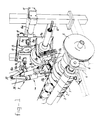
- Fig. 1 shows a perspective view of a part of the peeling machine.
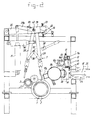
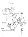
- Figs. 2 to 5 show a cross section of the machine, in which the transfer mechanism for transferring onions from guide means to peeling means takes up different positions.
- Fig. 6 shows a side view of one half of the knife-holder.
- Fig. 7 shows a front view of a part of the knife-holder.
- the peeling machine shown is intended for removing the outer skins of onions or other bulbous or tuberous plants.
- the machine comprises a guide mechanism, known per se and disclosed in European Patent Application 0,174,697, which guides onions into a position in which the line through top and tail takes up a certain position, preferably a position in which said line is at right angles to the plane of knives, to be described in greater detail, for topping and tailing.
- This guide mechanism comprises a roller 1 which has cut into it a spiral groove 2, and a roller 3 which is fitted a short distance away next to the roller 1 and is parallel thereto.
- These rollers 1 and 3 are driven via a belt 4 and belt pulleys 5, 6 by a motor which is not shown.
- the peripheral speed of the roller 3 is slightly higher than that of the roller 1. This helps to guide the infed onions in such a way that the line through head and tail of the onions extends in the axial direction of the rollers.
- a transfer mechanism 7 of a design yet to be discussed can transfer the guided onions from the guide means to the peeling means.
- Said peeling means comprise two circular knives 8a, 8b rotatably mounted on carriages 9a, 9b respectively, which can travel along a fixed rail 11 by means of wheels 10.
- the carriages are drawn towards each other by a spring 12.
- a spacer 13 is provided between the carriages.
- Each of the carriages has fixed thereon by means of a bracket 14a, 14b a bar 15a, 15b which can slide freely to and fro along a limited distance.
- the carriages can be pushed towards each other by means of cylinders 16a, 16b containing a piston to be actuated by compressed air.
- a pilot pin 17a, 17b is also fixed on each of the carriages.
- the height of and spacing between these pilot pins are adjustable. Their function is to adjust the distance between the circular knives 8a, 8b to the length of each onion brought in by the mechanisms in such a way that the head and tail are cut off at the desired point by the rotary knives.
- the knives can move freely to and fro along a certain distance by means of the bars 15a, 15b, and they are pushed towards each other only by the power of the spring 12.
- the peeling is carried out by making a circumferential cut in the clamped onion and blowing off the outer skins with compressed air.
- a knife-holder 19, which can be moved to and fro by a pneumatic cylinder 18 and which is provided with a semi-circular recess on the periphery from which the points of a number of knives 20 project, is used to make the circumferential cut.
- Fig. 6 shows the open knife-holder 19 with the knives 20.
- Fig. 5 shows a knife-holder in the cutting position.
- the onion will be centred if the knives 8a, 8b functioning as clamping plates are centred.
- a circumferential cut with a depth corresponding to the distance along which the knives 20 extend is produced in the onion.
- a separate Bowden cable 41 which is connected to a motor (not shown).
- Telescopic shafts connected to each other by cross couplings can be used instead of a Bowden cable.
- one or more nozzles 21, connected to a compressed air source are disposed in the knife-holder right next to a knife 20.
- nozzles 21 opening into a curved line 22, which is in turn connected to a hollow guide pipe 23 connected to the source by means of a hose 24.
- the other guide pipe 25 plays no role in the infeed of compressed air.
- the two pipes 23, 25 project through bushes, and their function is to guide the movement of the knife-holder.
- the piston rod of the cylinder 18 is indicated by 26.
- the transfer means 7 comprise tongs with a front leg 27 and a rear leg 28.
- the latter pivots relative to a fixed block 29 of the front leg.
- the pivot point has been given the reference number 40.
- the front leg 27 can be operated by a cylinder 30, and the rear leg 28 by a cylinder 31.
- the block 29 has a lobe 32 which can come into contact with a top stop screw 33 and a bottom stop screw 34. Both screws 33, 34 form part of a hinged arm 35 which is mounted on the frame of the machine, and which is also provided with a stop 39.
- Twin-legged shears 36 are disposed between the legs 27 and 28 of the tongs.
- the position of the common hinge point 37 of these shears can be established by a sensor 38 when the hinge point 37 passes the sensor head (Fig. 4).
- the transfer mechanism 7 works as follows: In Fig. 2 the tongs 2 are in a low position and are on the point of removing an onion from the guide device 1, 2, 3. In the double-acting air cylinder 30 there is a preliminary pressure of about 2 bars at the bar side. Actuation of the air cylinder 31 causes the leg 28 to move forward, the onion is clamped between the legs 28 and 27 and the two legs with onion are moved forward to the position shown in Fig. 3. During this movement the tops and tails are removed by the knives 8a, 8b.
Landscapes
- Life Sciences & Earth Sciences (AREA)
- Chemical & Material Sciences (AREA)
- Engineering & Computer Science (AREA)
- Food Science & Technology (AREA)
- Polymers & Plastics (AREA)
- Apparatuses For Bulk Treatment Of Fruits And Vegetables And Apparatuses For Preparing Feeds (AREA)
- Cultivation Of Plants (AREA)
Abstract
Description
- The invention relates to a device for peeling onions or other bulbous or tuberous plants, comprising a holder with one more more knives for making a circumferential cut in the onions and at least one nozzle for the infeed of compressed air or another pressurized medium for removing the peelings.
- Such a device is described in European patent application 0,114,715.
- Onions which are to be processed into rings, dice and similar pieces are peeled, i.e. the brown skins and the outer fleshy skin are removed and they are topped and tailed. A peeling loss of about 30% is considered acceptable. Onions which are to go through a drying process need not be totally skinned, in other words only the brown skins and the tops and tails need be removed which means that the peeling loss can be limited to about 10 to 15%. Peeling off the skins and topping and tailing are still carried out by hand. There are cutting meachines in which onions inserted on pins are conveyed past rotary knives to cut off the heads and tails. The onions damaged by the pins generally have a reduced shelf life. There are also machines on the market for rubbing off the skins by means of Carborundum-containing elements or for peeling the onions with knives. The treatment with these machines leads to greatly damaged onions and high peeling losses. The peeled product falls far short of the high quality and attractive appearance of onions peeled by hand. Another known method is to subject onions to a caustic solution or steam treatment to loosen the outer skins. Peeling with caustic solution leads to an effluent problem, and the appearance of the peeled product is not so attractive. Steam-peeling has the disadvantage that some of the product bursts if there is sudden expansion of the steam tank and the onions consequently acquire an irregular appearance. There are quite a number of peeling systems which have the object of reducing manual work to a minimum and which lead to too much misproduct (head and tail removed at the wrong place, skin not removed completely, and the like) and too many other disadvantages (including high peeling loss, usable only for a certain size, low capacity of peeled product per person per hour, not so good external quality, limited shelf life, effluent problems and the like). Peeling by hand is, on the other hand, expensive and involves the risk of microbiological contamination. There is therefore a need for a non-manual peeling method for onions which does not have the above-mentioned disadvantages.
- The devices according to the above-mentioned European patent application which operate on the principle of scoring along a circumferential cut and blowing away the skins, do produce onions with little damage and a low peeling loss, but it is found in practice that the skins to be removed are often not (properly) blown away by the compressed medium.
- The object of the invention is to eliminate this disadvantage, and to this end the device mentioned in the preamble is characterized in that the knife-holder has an approximately semi-circular arch-shaped recess, and a number of knives are fitted along the periphery of said recess and that each of the nozzles for the supply of pressurized medium is fitted in or on the knife-holder between two knives.
- It was surprizingly found that through this simple measure a much greater percentage of the skins to be removed is blown away, and the peeling output can be improved considerably without damage to the onions.
- If the device has guide means which are known per se for taking the line through head and tail of the onions in a specific direction, the device preferably has two rotary parallel clamping plates for clamping an onion, means for moving the clamping plates towards and away from each other, transfer means for transferring an onion from the guides means to a position between the clamping plates, and means for moving the knife-holder in the direction of a position situated centrally between the clamping plates, and back.
- The clamping plates can also be used for topping and tailing the onions; in that case they are designed as circular knives.
- In order to make the circular knives go in a simple manner into the desired position relative to each other for topping and tailing and also to be able to push the circular knives towards each other for temporary clamping of the onions, they are supported on carriages which are movable along a limited distance on bars, which in turn can be moved by the above-mentioned means for moving the clamping plates away from and towards each other, said carriages being pulled or pushed towards each other by spring means.
- The carriages are preferably provided with pilot elements for adjusting the distance between the circular knives to the length of the onions.
- All kinds of mechanisms are conceivable for transferring the onions from the guide means to the peeling means. In practice, a very reliable and easily regulated transfer means was found to be one having tongs with two hinged legs, in which control means are present for moving the tongs to the guide means, moving the legs of the tongs towards each other for picking up an onion, pivoting the tongs between the clamping means, moving the legs of the tongs away from each other, and moving the tongs away from the clamping means and returning them to the initial position above the guide means.
- The invention will now be explained in greater detail with reference to the figures, in which an example of an embodiment is shown.
- Fig. 1 shows a perspective view of a part of the peeling machine.
- Figs. 2 to 5 show a cross section of the machine, in which the transfer mechanism for transferring onions from guide means to peeling means takes up different positions.
- Fig. 6 shows a side view of one half of the knife-holder.
- Fig. 7 shows a front view of a part of the knife-holder.
- The peeling machine shown is intended for removing the outer skins of onions or other bulbous or tuberous plants. The machine comprises a guide mechanism, known per se and disclosed in European Patent Application 0,174,697, which guides onions into a position in which the line through top and tail takes up a certain position, preferably a position in which said line is at right angles to the plane of knives, to be described in greater detail, for topping and tailing. This guide mechanism comprises a
roller 1 which has cut into it aspiral groove 2, and aroller 3 which is fitted a short distance away next to theroller 1 and is parallel thereto. Theserollers belt pulleys roller 3 is slightly higher than that of theroller 1. This helps to guide the infed onions in such a way that the line through head and tail of the onions extends in the axial direction of the rollers. - A transfer mechanism 7 of a design yet to be discussed can transfer the guided onions from the guide means to the peeling means.
- Said peeling means comprise two circular knives 8a, 8b rotatably mounted on
carriages rail 11 by means ofwheels 10. The carriages are drawn towards each other by aspring 12. In order to ensure that the distance between thecarriages spacer 13 is provided between the carriages. Each of the carriages has fixed thereon by means of abracket 14a, 14b abar cylinders pilot pin bars spring 12. Once an onion is carried by the mechanism 7 approximately into the centre of the knives 8a, 8b (where it is topped and tailed) a signal is passed to the compressed air supply valve of thecylinders - The peeling is carried out by making a circumferential cut in the clamped onion and blowing off the outer skins with compressed air. A knife-
holder 19, which can be moved to and fro by apneumatic cylinder 18 and which is provided with a semi-circular recess on the periphery from which the points of a number ofknives 20 project, is used to make the circumferential cut. Fig. 6 shows the open knife-holder 19 with theknives 20. - Fig. 5 shows a knife-holder in the cutting position. As a result of the semi-circular shape of the recess boundary, the onion will be centred if the knives 8a, 8b functioning as clamping plates are centred. A circumferential cut with a depth corresponding to the distance along which the
knives 20 extend is produced in the onion. For the rotation of one of the knives 8a, 8b use is made of a separate Bowdencable 41 which is connected to a motor (not shown). Telescopic shafts connected to each other by cross couplings can be used instead of a Bowden cable. - It is essential for the invention that one or
more nozzles 21, connected to a compressed air source, are disposed in the knife-holder right next to aknife 20. In the example shown there are twonozzles 21 opening into acurved line 22, which is in turn connected to ahollow guide pipe 23 connected to the source by means of ahose 24. Theother guide pipe 25 plays no role in the infeed of compressed air. The twopipes - Since the compressed air is always blown directly into the circumferential cut made a very short distance from a knife point, the peeling efficiency is very high. In other words, very much more skin is removed in a very simple manner than in the case of a design in which the
nozzles 21 are not incorporated in the knife-holder. The piston rod of thecylinder 18 is indicated by 26. - The transfer means 7 comprise tongs with a
front leg 27 and arear leg 28. The latter pivots relative to afixed block 29 of the front leg. The pivot point has been given thereference number 40. Thefront leg 27 can be operated by acylinder 30, and therear leg 28 by acylinder 31. - The
block 29 has alobe 32 which can come into contact with a top stop screw 33 and abottom stop screw 34. Both screws 33, 34 form part of a hingedarm 35 which is mounted on the frame of the machine, and which is also provided with astop 39. - Twin-
legged shears 36 are disposed between thelegs common hinge point 37 of these shears can be established by asensor 38 when thehinge point 37 passes the sensor head (Fig. 4). - The transfer mechanism 7 works as follows: In Fig. 2 the
tongs 2 are in a low position and are on the point of removing an onion from theguide device air cylinder 30 there is a preliminary pressure of about 2 bars at the bar side. Actuation of theair cylinder 31 causes theleg 28 to move forward, the onion is clamped between thelegs - The position of the
legs sensor 38 which reacts to the passinghinge point 37. In this position the onion is in the centre of the knives 8a, 8b. After a signal from thesensor 38 the following actions, partially overlapping each other, are now undertaken: - 1) Compressed air is conveyed to the
cylinders - 2) The
air cylinder 30 is actuated so that theleg 27 of the tongs moves forward until thelobe 32 comes into contact with the stop 33. - 3) Compressed air is conveyed under the piston of the
cylinder 31, so that theleg 28 of the tongs pivots away from theleg 27 of the tongs, until thepart 28a of theleg 28 comes into contact with thestop 39 on the hinged arm 35 (Fig. 4). - 4) Further movement upwards of the piston of the
cylinder 31 causes the entire tongs to be moved upwards to the position shown in Fig. 5. During this movement the piston of thecylinder 30 is blocked and the two legs rotate about thehinge point 40 of the tongs. - Through the respective retraction of the piston rod of the
cylinder 30 and the retraction of the piston rod of thecylinder 31, the initial position according to Fig. 2 is achieved, following which the next onion can be picked up and can be subjected to the peeling treatment. - Other mechanisms are also conceivable for transferring the onions from the guide means to the scoring and blowing means. It is greatly preferable for topping and tailing to be carried out while an onion is being moved from the guide means to the peeling means, while the circular knives intended for the purpose also serve as clamping means for clamping the onion in a position in which a score can be made along the circumference of the onion and the loosened skins can be blown away by means of one or more nozzles which are situated in the knife-holder right next to the knives.
Claims (6)
Priority Applications (1)
| Application Number | Priority Date | Filing Date | Title |
|---|---|---|---|
| AT89200105T ATE78135T1 (en) | 1988-02-02 | 1989-01-18 | PEELING MACHINE FOR ONIONS OR TUBERS OR ROOTS. |
Applications Claiming Priority (2)
| Application Number | Priority Date | Filing Date | Title |
|---|---|---|---|
| NL8800250 | 1988-02-02 | ||
| NL8800250A NL8800250A (en) | 1988-02-02 | 1988-02-02 | Apparatus for peeling onions or other bulbous or tuberous plants. |
Publications (2)
| Publication Number | Publication Date |
|---|---|
| EP0327146A1 EP0327146A1 (en) | 1989-08-09 |
| EP0327146B1 true EP0327146B1 (en) | 1992-07-15 |
Family
ID=19851698
Family Applications (1)
| Application Number | Title | Priority Date | Filing Date |
|---|---|---|---|
| EP89200105A Expired - Lifetime EP0327146B1 (en) | 1988-02-02 | 1989-01-18 | Device for peeling onions or other bulbous or tuberous plants |
Country Status (7)
| Country | Link |
|---|---|
| US (1) | US4889046A (en) |
| EP (1) | EP0327146B1 (en) |
| AT (1) | ATE78135T1 (en) |
| DE (1) | DE68902060T2 (en) |
| ES (1) | ES2028759T3 (en) |
| GR (1) | GR3005205T3 (en) |
| NL (1) | NL8800250A (en) |
Families Citing this family (11)
| Publication number | Priority date | Publication date | Assignee | Title |
|---|---|---|---|---|
| US5178057A (en) * | 1989-03-09 | 1993-01-12 | State Of Israel-Ministry Of Agriculture | Apparatus for removing pulp from fruit |
| JP2925213B2 (en) * | 1990-01-23 | 1999-07-28 | 株式会社長岡精機製作所 | Cutting device for stem and root of bulb |
| JP2938109B2 (en) * | 1990-01-23 | 1999-08-23 | 株式会社長岡精機製作所 | Bulb slitting machine |
| DE4118604A1 (en) * | 1991-06-06 | 1992-12-10 | Frans Popma | PLANT FOR REMOVING PART OF A COMPACT FRUIT |
| NL1000531C2 (en) * | 1994-12-29 | 1996-07-01 | Compas B V Maschf | Waste removal from vegetables using recycled air as transport means |
| US5465657A (en) * | 1995-02-13 | 1995-11-14 | Wu; Hsiu-Liang | Device for removing outer membrane of scallion head or garlic head |
| US20050244558A1 (en) * | 2003-12-18 | 2005-11-03 | Shearer Richard C | Method for preserving peeled whole onions |
| EP1982605A1 (en) * | 2007-04-16 | 2008-10-22 | Gourmet B.V. | Peeled onion and method for peeling an onion |
| EP1992237A3 (en) * | 2007-05-15 | 2009-01-14 | Egatec A/S | Apparatus for orienting non-round objects, in particular bulbs |
| US11606911B2 (en) * | 2018-03-27 | 2023-03-21 | Eteros Technologies Usa, Inc. | Plant material trimming device |
| JP2021010330A (en) * | 2019-07-06 | 2021-02-04 | 渡辺精機株式会社 | Both ends cutting device for spherical vegetable |
Family Cites Families (14)
| Publication number | Priority date | Publication date | Assignee | Title |
|---|---|---|---|---|
| US1720468A (en) * | 1928-08-27 | 1929-07-09 | Combest Ross | Rotary fruit and vegetable stemming, peeling, and trimming head |
| US2445881A (en) * | 1945-12-18 | 1948-07-27 | Us Agriculture | Apparatus for peeling onions, including a conical jet of gas |
| US3696848A (en) * | 1970-07-22 | 1972-10-10 | Marriott Corp | Method and apparatus for removing skin from onions or like vegetables |
| DE2346191A1 (en) * | 1972-09-21 | 1974-03-28 | Vogelaar Matthijs Pieter | DEVICE FOR AUTOMATIC PROCESSING OF ONION AND TUBER GROWS |
| NL8000484A (en) * | 1980-01-25 | 1981-08-17 | Gabor Janos Raatz | INDUSTRIAL PEELER FOR ONIONS AND SIMILAR BULBS AND BUTTON CROPS. |
| US4476778A (en) * | 1980-07-21 | 1984-10-16 | Spring Gully Pickles Pty, Limited | Onion peeling |
| EP0109987A1 (en) * | 1982-11-24 | 1984-06-13 | M.G.I. Co., Ltd. | Apparatus for peeling bulbs |
| US4481875A (en) * | 1982-12-03 | 1984-11-13 | M.G.I. Co., Ltd. | Bulb peeling apparatus |
| NL8300221A (en) * | 1983-01-21 | 1984-08-16 | North Invest Finance | INDUSTRIAL ONION PEELER. |
| US4470345A (en) * | 1983-04-26 | 1984-09-11 | Hiroyuki Miyata | Apparatus for peeling skins off the bulbs of onions |
| JPS60126069A (en) * | 1983-12-12 | 1985-07-05 | Shozo Suzuki | Onion peeler |
| JPS60241878A (en) * | 1984-05-14 | 1985-11-30 | Nagaoka Seiki Seisakusho:Kk | Apparatus for cutting stem part and root part of scaly bulb |
| NL8402721A (en) * | 1984-09-06 | 1986-04-01 | Inst Voor Bewaring | METHOD AND APPARATUS FOR PEELING ONIONS. |
| IT1187777B (en) * | 1985-03-22 | 1987-12-23 | Campesato Marino & Figli Snc | BULB PEELING MACHINE IN GENERAL, SUCH AS ONIONS |
-
1988
- 1988-02-02 NL NL8800250A patent/NL8800250A/en not_active Application Discontinuation
-
1989
- 1989-01-18 AT AT89200105T patent/ATE78135T1/en not_active IP Right Cessation
- 1989-01-18 ES ES198989200105T patent/ES2028759T3/en not_active Expired - Lifetime
- 1989-01-18 EP EP89200105A patent/EP0327146B1/en not_active Expired - Lifetime
- 1989-01-18 DE DE8989200105T patent/DE68902060T2/en not_active Expired - Fee Related
- 1989-01-26 US US07/302,405 patent/US4889046A/en not_active Expired - Fee Related
-
1992
- 1992-07-16 GR GR920401454T patent/GR3005205T3/el unknown
Also Published As
| Publication number | Publication date |
|---|---|
| DE68902060D1 (en) | 1992-08-20 |
| ES2028759T1 (en) | 1992-07-16 |
| DE68902060T2 (en) | 1993-01-14 |
| GR3005205T3 (en) | 1993-05-24 |
| ATE78135T1 (en) | 1992-08-15 |
| NL8800250A (en) | 1989-09-01 |
| EP0327146A1 (en) | 1989-08-09 |
| ES2028759T3 (en) | 1993-03-01 |
| US4889046A (en) | 1989-12-26 |
Similar Documents
| Publication | Publication Date | Title |
|---|---|---|
| EP0327146B1 (en) | Device for peeling onions or other bulbous or tuberous plants | |
| US4773324A (en) | Broccoli trimming machine | |
| US4745660A (en) | Universal shrimp peeling machine | |
| ES2004606A6 (en) | Fruit gripper head assembly | |
| US4073041A (en) | Crab butchering machine | |
| EP0174697B1 (en) | Appliance for the alignment of onions or other vegatable bulbs | |
| US4658714A (en) | Apparatus for cutting broccoli and other long stemmed vegetables | |
| US3638696A (en) | Means for peeling pineapples | |
| CN109910125B (en) | Full-automatic rotary cinnamon peeling machine | |
| CN111418855A (en) | Automatic change sugarcane and handle and use mechanical equipment | |
| US3700017A (en) | Citrus fruit peeling machine | |
| CA1306171C (en) | Method and apparatus for pretreating and debarking logs | |
| JPS63503298A (en) | Methods and equipment for pruning, bark stripping, and chipping (wood chips) | |
| JP5467638B2 (en) | Bar vegetable peeling machine | |
| CN210046802U (en) | Peeling device and automatic peeling machine | |
| KR20210145921A (en) | Device for peeling onion shell | |
| CN210046801U (en) | Peeling device and automatic peeling machine | |
| CN109849139B (en) | Full-automatic plowing type cinnamon peeling machine | |
| EP0721738B1 (en) | Method and apparatus for peeling sausages | |
| US3618650A (en) | Apparatus for preparing the receptacles and fruits of bractated plants, more particularly artichokes | |
| US3126930A (en) | Onion coring | |
| US3734002A (en) | Means for peeling pineapples | |
| CN210987982U (en) | Automatic cutting and dirty removing device for freshwater fish body | |
| CN211861733U (en) | Fruit processing equipment | |
| US2888969A (en) | Tomato peeling machine |
Legal Events
| Date | Code | Title | Description |
|---|---|---|---|
| PUAI | Public reference made under article 153(3) epc to a published international application that has entered the european phase |
Free format text: ORIGINAL CODE: 0009012 |
|
| AK | Designated contracting states |
Kind code of ref document: A1 Designated state(s): AT BE CH DE ES FR GB GR IT LI LU NL SE |
|
| 17P | Request for examination filed |
Effective date: 19900104 |
|
| 17Q | First examination report despatched |
Effective date: 19910307 |
|
| GRAA | (expected) grant |
Free format text: ORIGINAL CODE: 0009210 |
|
| AK | Designated contracting states |
Kind code of ref document: B1 Designated state(s): AT BE CH DE ES FR GB GR IT LI LU NL SE |
|
| REF | Corresponds to: |
Ref document number: 78135 Country of ref document: AT Date of ref document: 19920815 Kind code of ref document: T |
|
| ITF | It: translation for a ep patent filed | ||
| REF | Corresponds to: |
Ref document number: 68902060 Country of ref document: DE Date of ref document: 19920820 |
|
| ET | Fr: translation filed | ||
| PGFP | Annual fee paid to national office [announced via postgrant information from national office to epo] |
Ref country code: GR Payment date: 19921126 Year of fee payment: 5 |
|
| PGFP | Annual fee paid to national office [announced via postgrant information from national office to epo] |
Ref country code: GB Payment date: 19930108 Year of fee payment: 5 |
|
| PGFP | Annual fee paid to national office [announced via postgrant information from national office to epo] |
Ref country code: FR Payment date: 19930111 Year of fee payment: 5 Ref country code: ES Payment date: 19930111 Year of fee payment: 5 |
|
| PGFP | Annual fee paid to national office [announced via postgrant information from national office to epo] |
Ref country code: AT Payment date: 19930113 Year of fee payment: 5 |
|
| PGFP | Annual fee paid to national office [announced via postgrant information from national office to epo] |
Ref country code: SE Payment date: 19930115 Year of fee payment: 5 |
|
| PGFP | Annual fee paid to national office [announced via postgrant information from national office to epo] |
Ref country code: CH Payment date: 19930125 Year of fee payment: 5 |
|
| PGFP | Annual fee paid to national office [announced via postgrant information from national office to epo] |
Ref country code: NL Payment date: 19930131 Year of fee payment: 5 |
|
| PGFP | Annual fee paid to national office [announced via postgrant information from national office to epo] |
Ref country code: DE Payment date: 19930209 Year of fee payment: 5 |
|
| PGFP | Annual fee paid to national office [announced via postgrant information from national office to epo] |
Ref country code: LU Payment date: 19930217 Year of fee payment: 5 |
|
| PGFP | Annual fee paid to national office [announced via postgrant information from national office to epo] |
Ref country code: BE Payment date: 19930226 Year of fee payment: 5 |
|
| REG | Reference to a national code |
Ref country code: GR Ref legal event code: FG4A Free format text: 3005205 |
|
| REG | Reference to a national code |
Ref country code: ES Ref legal event code: FG2A Ref document number: 2028759 Country of ref document: ES Kind code of ref document: T3 |
|
| EPTA | Lu: last paid annual fee | ||
| PLBE | No opposition filed within time limit |
Free format text: ORIGINAL CODE: 0009261 |
|
| STAA | Information on the status of an ep patent application or granted ep patent |
Free format text: STATUS: NO OPPOSITION FILED WITHIN TIME LIMIT |
|
| 26N | No opposition filed | ||
| PG25 | Lapsed in a contracting state [announced via postgrant information from national office to epo] |
Ref country code: LU Free format text: LAPSE BECAUSE OF NON-PAYMENT OF DUE FEES Effective date: 19940118 Ref country code: GB Effective date: 19940118 Ref country code: AT Effective date: 19940118 |
|
| PG25 | Lapsed in a contracting state [announced via postgrant information from national office to epo] |
Ref country code: SE Effective date: 19940119 Ref country code: ES Free format text: LAPSE BECAUSE OF NON-PAYMENT OF DUE FEES Effective date: 19940119 |
|
| PG25 | Lapsed in a contracting state [announced via postgrant information from national office to epo] |
Ref country code: LI Effective date: 19940131 Ref country code: CH Effective date: 19940131 Ref country code: BE Effective date: 19940131 |
|
| BERE | Be: lapsed |
Owner name: INSTITUUT VOOR BEWARING EN VERWERKING VAN LANDBOU Effective date: 19940131 |
|
| PG25 | Lapsed in a contracting state [announced via postgrant information from national office to epo] |
Ref country code: GR Free format text: THE PATENT HAS BEEN ANNULLED BY A DECISION OF A NATIONAL AUTHORITY Effective date: 19940731 |
|
| PG25 | Lapsed in a contracting state [announced via postgrant information from national office to epo] |
Ref country code: NL Effective date: 19940801 |
|
| GBPC | Gb: european patent ceased through non-payment of renewal fee |
Effective date: 19940118 |
|
| NLV4 | Nl: lapsed or anulled due to non-payment of the annual fee | ||
| PG25 | Lapsed in a contracting state [announced via postgrant information from national office to epo] |
Ref country code: FR Effective date: 19940930 |
|
| REG | Reference to a national code |
Ref country code: CH Ref legal event code: PL |
|
| PG25 | Lapsed in a contracting state [announced via postgrant information from national office to epo] |
Ref country code: DE Effective date: 19941001 |
|
| REG | Reference to a national code |
Ref country code: FR Ref legal event code: ST |
|
| REG | Reference to a national code |
Ref country code: GR Ref legal event code: MM2A Free format text: 3005205 |
|
| EUG | Se: european patent has lapsed |
Ref document number: 89200105.8 Effective date: 19940810 |
|
| REG | Reference to a national code |
Ref country code: ES Ref legal event code: FD2A Effective date: 19990503 |
|
| PG25 | Lapsed in a contracting state [announced via postgrant information from national office to epo] |
Ref country code: IT Free format text: LAPSE BECAUSE OF NON-PAYMENT OF DUE FEES Effective date: 20050118 |