EP0174697B1 - Appliance for the alignment of onions or other vegatable bulbs - Google Patents
Appliance for the alignment of onions or other vegatable bulbs Download PDFInfo
- Publication number
- EP0174697B1 EP0174697B1 EP85201416A EP85201416A EP0174697B1 EP 0174697 B1 EP0174697 B1 EP 0174697B1 EP 85201416 A EP85201416 A EP 85201416A EP 85201416 A EP85201416 A EP 85201416A EP 0174697 B1 EP0174697 B1 EP 0174697B1
- Authority
- EP
- European Patent Office
- Prior art keywords
- onions
- appliance
- cylinder
- alignment
- appliance according
- Prior art date
- Legal status (The legal status is an assumption and is not a legal conclusion. Google has not performed a legal analysis and makes no representation as to the accuracy of the status listed.)
- Expired
Links
- 241000234282 Allium Species 0.000 title claims abstract description 107
- 235000002732 Allium cepa var. cepa Nutrition 0.000 title claims abstract description 107
- 235000013311 vegetables Nutrition 0.000 claims abstract description 4
- 230000004323 axial length Effects 0.000 claims abstract 3
- 230000007246 mechanism Effects 0.000 claims description 44
- 238000012545 processing Methods 0.000 claims description 7
- 238000012546 transfer Methods 0.000 claims description 6
- 230000009471 action Effects 0.000 claims description 3
- 241000549194 Euonymus europaeus Species 0.000 claims description 2
- 238000006073 displacement reaction Methods 0.000 claims description 2
- 238000004804 winding Methods 0.000 claims description 2
- 241000227653 Lycopersicon Species 0.000 description 7
- 235000007688 Lycopersicon esculentum Nutrition 0.000 description 7
- 238000010438 heat treatment Methods 0.000 description 5
- 239000007787 solid Substances 0.000 description 5
- 238000010276 construction Methods 0.000 description 4
- 230000032258 transport Effects 0.000 description 4
- 238000000034 method Methods 0.000 description 3
- 230000008569 process Effects 0.000 description 3
- 206010013786 Dry skin Diseases 0.000 description 2
- 238000013461 design Methods 0.000 description 2
- 230000037336 dry skin Effects 0.000 description 2
- 239000002351 wastewater Substances 0.000 description 2
- 241001500843 Allium parvum Species 0.000 description 1
- 229910000639 Spring steel Inorganic materials 0.000 description 1
- 238000013459 approach Methods 0.000 description 1
- 230000009286 beneficial effect Effects 0.000 description 1
- 230000008602 contraction Effects 0.000 description 1
- 238000001035 drying Methods 0.000 description 1
- 230000000694 effects Effects 0.000 description 1
- 230000001771 impaired effect Effects 0.000 description 1
- 230000001788 irregular Effects 0.000 description 1
- 238000011169 microbiological contamination Methods 0.000 description 1
- 238000012986 modification Methods 0.000 description 1
- 230000004048 modification Effects 0.000 description 1
- 238000005096 rolling process Methods 0.000 description 1
- 229910010271 silicon carbide Inorganic materials 0.000 description 1
- 239000007921 spray Substances 0.000 description 1
- 230000001360 synchronised effect Effects 0.000 description 1
- 238000005406 washing Methods 0.000 description 1
- XLYOFNOQVPJJNP-UHFFFAOYSA-N water Substances O XLYOFNOQVPJJNP-UHFFFAOYSA-N 0.000 description 1
Images

Classifications
-
- A—HUMAN NECESSITIES
- A23—FOODS OR FOODSTUFFS; TREATMENT THEREOF, NOT COVERED BY OTHER CLASSES
- A23N—MACHINES OR APPARATUS FOR TREATING HARVESTED FRUIT, VEGETABLES OR FLOWER BULBS IN BULK, NOT OTHERWISE PROVIDED FOR; PEELING VEGETABLES OR FRUIT IN BULK; APPARATUS FOR PREPARING ANIMAL FEEDING- STUFFS
- A23N15/00—Machines or apparatus for other treatment of fruits or vegetables for human purposes; Machines or apparatus for topping or skinning flower bulbs
- A23N15/08—Devices for topping or skinning onions or flower bulbs
Definitions
- the invention relates to an appliance for the alignment of onions or other vegetable bulbs.
- Onions intended for consumption must in general be subjected to one or more processes. These processes may be, inter alia: the removal of top and root ends, the removal of the outermost skins and the cutting of the onions into slices. If these processes do not take place by hand but by machine, the onions will have to be presented to the respective processing machine with their axial direction in a particular position. This oriented presentation can of course take place by hand, but this is a labour-intensive, relatively costly job.
- US Patent Specification 1 581 071 discloses a tomato washing, scalding and peeling machine comprising a cylinder with a helical groove in the outer surface thereof and means of driving to rotate the grooved cylinder. By rotating the cylinder the tomatoes roll over one another. A brush assists in rolling the tomatoes. As the tomatoes travel along the cylinder, they pass through alternate sprays of cold and hot water. which both wash them and cause expansion and contraction of the tomato skin so that it will crack and will be loosened. The helical groove will have a certain guiding influence on the tomatoes. however, this influence is insufficient to align the tomatoes to a position in which the central axis takes up a particular position.
- the objective of the invention is to provide an appliance for the alignment of onions or other vegetable bulbs to a position in which the line through the top and the root end takes up a particular position, the onions not undergoing any mechanical damage as a result of the alignment and virtually 100% of the onions to be aligned being oriented to the correct position, even if there are large differences in shape between the onions.
- the width of the helical groove must be matched to the dimensions of the onions. If only graded onions whose dimensions lie between fixed narrow limits are oriented, the width of the helical groove can always be the same and the grooved cylinder can consist of a tube in the inner or outer surface of which the groove is recessed. In general, however, it is preferable if the width of the helical groove can be adjusted and can thus be matched to different onion dimensions.
- An appliance in which the width of the helical groove can easily be adjusted comprises two helical rods of equal diameter which are mounted on a common spindle to be driven in a rotary manner and between which the helical groove is situated, while the axial distance between the helical rods is adjustable.
- the onions must only land in a groove of the desired adjusted width. Between the helical rods there is also a helical groove which is not intended for the orientation of the onions and to prevent the onions landing in this groove use is made of a fill up helix which extends between two pairs of windings of the said helical rods.
- This fill-up helix will have a diameter in the said first design of the invention which is somewhat larger than the diameter of the helical rods which limit the orientation groove, while in the said second design the fill-up helix will have a diameter which is somewhat less than the diameter of the helical rods which limit the orientation groove.
- a gripping jaw mechanism which preferably consists of a spindle piece to be driven in a rotary manner to which are connected at least one fixed pin and at least one pivotable pin, means being present to pilot the pivotable pin into a gripping position and into an open position with respect to the fixed pin.
- This gripping jaw mechanism conveys the onions, for example through knives which cut off the top and root end.
- a transfer mechanism comprising a spindle to be driven in a rotary manner, two pivotable levers linked to it, means of pivoting the levers away from each other and towards each other and gripping elements at the end of the lever intended for gripping the onions by the axial end parts.
- Onions which are intended to be processed into rings little blocks and similar pieces are usually peeled, i.e. the dry skins and the outermost fleshy skin are removed and the top and root end are cut off them.
- a peeling loss of approx. 30% is considered acceptable.
- Onions intended for a drying process do not have to be completely clean, i.e. only the dry skins and the top and root end have to be removed, as a result of which the peeling loss may remain limited to approx. 10-15%.
- the peeling off of the layers and the cutting off of the top and root end is still often done by hand.
- There exist cutting machines in which onions speared on pins are carried passed rotating knives to cut the tops and root ends off them. The onions damaged by the pins in general exhibit reduced keeping properties.
- An appliance for the peeling of onions whose top and root end have been removed by hand or mechanically is characterised for this purpose by a "pop-out" mechanism formed by two gripping faces which can grip the outermost skin or skins and can give the onions the opportunity of escaping from the outermost skins in the axial direction when pressure is exerted on the gripping faces or a lateral force is exerted on the onions.
- the onions could be brought successively between two moving flexible transport elements, the outermost skins gripped by means of a profiled piece, the onions being pushed out of the gripped skins by a moving or stationary disc or strip projecting between the transport elements.
- the said gripping faces consist of a disc, to some extent flexible, which projects from a fixed support and a pushing strip displaceable towards the flexible strip.
- top and root end pieces should be removed from the onions beforehand, the reason being that the onions leave their outmost skins during the popping out via an opening in the skin formed by the cutting off of the top or root end.
- this cutting off In order to cause this cutting off to take place fully automatically immediately before the popping out, use is made of two knives placed next to each other at a certain distance, the pushing strip having a displacement path which is situated between the knives. It is of importance that the machine is suitable for fairly large and fairly small onions and that the knives always take up the desired position with respect to the top and root ends to be removed.
- the knives are each mounted on an arm, which arms are pivotable laterally against spring action, each arm having a pilot pin to be brought into contact with the onions to cause the pivoting of the arms to a position in which the knives are situated in the correct position with respect to the top and root end parts to be removed.
- a pipe for the supply of steam may extend parallel to and in the vicinity of the alignment transporter.
- the onion peeling machine shown in Figures 1 to 3 incl. comprises, a) an alignment mechanism for orienting the onions into the processing position, b) means of heat treatment for loosening the outermost skins of the onions, c) a cutting mechanism for the removal of top and root end of the oriented onions, and d) a pop-out mechanism for popping or shooting out the onions axially from the outermost skins.
- the invention is concerned in the first place with the alignment mechanism.
- This mechanism brings the onions into a well oriented position in which the further operations can be carried out without problems. Examples of the operations are the said removal of top and root ends, and the popping of the onions axially out of the outermost skins.
- other facilities may also follow the alignment mechanism, for example a mechanism for notching the onions around the circumference and removing them in the radial direction from the divided outer skins or a mechanism for cutting the onions into slices.
- the alignment appliance now to be described can be used in conjunction with any known mechanism for which aligned presentation to the mechanism is essential for a good operation.
- the alignment mechanism consists of a closed roller 1 and a helical roller formed by two helical rods 2, 3 which are mounted on a spindle 4 by means of plates 5 with a mutually adjustable axial spacing, the spacing thereof being capable of being altered by the screw bolt 6.
- the closed roller 1 and the helical roller 2 are mounted next to each other in a frame 7. They are driven by belts or chains 8 which lead to a common motor (not shown).
- the direction of rotation of the roller 1 and the helical rollers 2, 3 is indicated in Figure 2, but the possibility is not excluded of the rollers 1 or 2, 3 rotating in opposite directions.
- the onions to be peeled are fed through a feed mechanism (not shown) in the direction of the arrow into the gap between the solid roller 1 and the helical roller 2, 3.
- the feed mechanism meters out the onions one by one in a manner such that one onion always lands between the helices at points where the distance between them is minimum.
- a metering feed mechanism is not always necessary.
- the circumferential velocity of the solid roller is chosen somewhat larger than that of the helical roller, which is beneficial but not necessary for orienting the onions in a manner such that top and root end extends parallel to the axial direction of the roller.
- a pipe 9 provided with openings for the supplying of steam to the onions.
- the helical roller transports the aligned onions to the cutting mechanism, and during this transport the onions are subjected to the influence of the steam.
- the outermost fleshy skin is softened as a result of this so that the flesh inside the said soft skin can easily be released therefrom.
- the residence time of the onions in the steam is, for example, 30 seconds. The possibility is not excluded that the onions are subjected to the heat treatment before they are fed to the aligning, cutting and popping out mechanism. Certain onions on the whole do not require to be subjected to a heat treatment.
- a scooping up mechanism may be fitted consisting of a pushing strip 11 which is mounted on the final plate 5 and to which two carrier pins 12 are welded at a mutual distance.
- a pushing strip 11 which is mounted on the final plate 5 and to which two carrier pins 12 are welded at a mutual distance.
- This mechanism comprises two circular knives 13, 14 each mounted on a spindle, the bearing 15, 16 of which is mounted on an arm 17 or 18.
- Each of the arms is linked by a hinge 19 or 20 to the frame section in a manner such that it can pivot in the lateral direction, tension springs 21 or 22 pulling the arms towards each other.
- tension springs 21 or 22 pulling the arms towards each other.
- these springs are also fixed to a fixed plate 23. Stop elements 30 determine the minimum distance between the arms 17, 18.
- a pilot pin 24 or 25 is fixed which comes into contact with the onions scooped up by a scooping up mechanism 11, 12, as a result of which the arms 17 or 18 are moved apart against the action of the springs 21 or 22 to a position in which the knives 13, 14 mounted on the said arms are located in the correct position with respect to the top and root end to be removed.
- the pilot pins may be fork-shaped.
- the knives driven by a motor 28 via belts 26 and chains 27 cut off the top and root end of the onion.
- the onion is pushed by the assembly of pushing strip 11 and carrier pins 12 to a pop-out mechanism.
- This comprises an elastic strip 31, consisting, for example, of a stiff rubber or spring steel covered with a rubber layer, mounted on a support 29.
- An onion which is located between the pushing strip 11 and the elastic strip 31 deflected to some extent and pretreated outer skins are gripped by the rough surface of the strip reacts to the pressure exerted by the onion popping out sideways from the outermost skins in the axial direction, and this is illustrated in Figure 3.
- the strip 31 may be a spring-load stiff pivoting strip. To prevent the strips 11 and 31 damaging each other in the absence of an onion, the stop devices may be encountered.
- the embodiment shown with an elastic strip 31 is simple and cheap.
- the pop-out principle can, however, be applied in many kinds of ways.
- Known mechanisms for the removal of the outermost skins may also follow the alignment appliance, for example a mechanism in which a circumferential cut in the outermost skins is applied with a knife and the onions are driven out of the incised skins in the radial direction (see for example the UK Patent Specification 821,315).
- the onion is exposed to steam or heat treatment before the top and root end are cut off it.
- the cutting surfaces will then not be impaired.
- flame treatment may be used. The possibility exists of carrying out the steam or heat treatment beforehand, i.e. outside the machine described.
- a spindle 40 to be driven in a rotary manner, which is provided with two fingers 41 situated close to each other which moves an onion from the gap between the roller 1 and the construction 2, 3 upwards in the direction of a gripping jaw mechanism 42.
- This comprises a spindle 43, to be driven in a rotary manner, a piece 44 mounted thereon, two pairs of pins 45 permanently mounted on the piece 44 and two pairs of pivotable, hooked-shaped pins 46 mounted on the piece 44.
- hydraulic or pneumatic cylinders 47 the pins 46 can be brought into an open position or a closed gripping position with respect to the pins 45.
- the gripping position is indicated in Figure 4 at the top and bottom of the rotation path by full lines, while the open position (mutual angle between the pins 45, 46 approx. 45°) is indicated by dotted lines.
- the operation of the cylinders 47 takes place by means of microswitches (not shown) which react to certain positions of the rotating piece 44.
- the synchronisation of the rotary movements of the spindles 40 and 43 is such that at the moment when the open jaw 45, 46 approaches the helical construction 2, 3 during the downward part of the rotary movement, the fingers 41 push an onion into the jaw, after which the jaw is closed and entrained.
- the gripped onion passes two knives 48, 49 which cut off the top and root end and which are to be compared in terms of operation with the knives 13, 14 of the embodiment according to Figure 2.
- the onion moves with a defined orientation towards a transfer mechanism 50 consisting of two levers 51, 52 which are pivotably mounted on a spindle, to be driven in a rotary manner, the pivoting spindles 54, 55 being perpendicular to the rotation spindle 53.
- a pneumatic or hydraulic cylinder 56 which can pivot the levers away from each other or towards each other.
- a gripping disc 57 or 58 is spring mounted.
- the spindle 53 rotates with twice the speed of the spindle 43.
- the directions of rotation of the spindles 43 and 53 are so synchronised with respect to each other and the operation of the cylinders 47 and 56 are so adjusted to each other by microswitches or the like which react to the angular position of the spindles 43 or 53 that the onion presented by a gripping jaw 45, 46 is taken up by the discs 57, 58 which are caused to grip the flat onion surfaces and are rotated further around the spindle 53.
- the directions of rotation are always indicated by arrows.
- the onion gripped between the discs 57, 58 is passed, for example, to a mechanism (not shown) for the cutting of slices.
- the levers 51, 52 are pushed away from each other as soon as the onion has passed the slice cutting mechanism.
Landscapes
- Life Sciences & Earth Sciences (AREA)
- Chemical & Material Sciences (AREA)
- Engineering & Computer Science (AREA)
- Food Science & Technology (AREA)
- Polymers & Plastics (AREA)
- Apparatuses For Bulk Treatment Of Fruits And Vegetables And Apparatuses For Preparing Feeds (AREA)
- Percussion Or Vibration Massage (AREA)
- Management, Administration, Business Operations System, And Electronic Commerce (AREA)
- Medicines Containing Plant Substances (AREA)
Abstract
Description
- The invention relates to an appliance for the alignment of onions or other vegetable bulbs.
- Onions intended for consumption must in general be subjected to one or more processes. These processes may be, inter alia: the removal of top and root ends, the removal of the outermost skins and the cutting of the onions into slices. If these processes do not take place by hand but by machine, the onions will have to be presented to the respective processing machine with their axial direction in a particular position. This oriented presentation can of course take place by hand, but this is a labour-intensive, relatively costly job.
- US Patent Specification 1 581 071 discloses a tomato washing, scalding and peeling machine comprising a cylinder with a helical groove in the outer surface thereof and means of driving to rotate the grooved cylinder. By rotating the cylinder the tomatoes roll over one another. A brush assists in rolling the tomatoes. As the tomatoes travel along the cylinder, they pass through alternate sprays of cold and hot water. which both wash them and cause expansion and contraction of the tomato skin so that it will crack and will be loosened. The helical groove will have a certain guiding influence on the tomatoes. however, this influence is insufficient to align the tomatoes to a position in which the central axis takes up a particular position.
- The objective of the invention is to provide an appliance for the alignment of onions or other vegetable bulbs to a position in which the line through the top and the root end takes up a particular position, the onions not undergoing any mechanical damage as a result of the alignment and virtually 100% of the onions to be aligned being oriented to the correct position, even if there are large differences in shape between the onions.
- The object of the invention is solved by an appliance as defined in Claim 1.
- It emerges that if the onions are introduced between the grooved cylinder and the roller, the onions land in the helical groove, are transported to the removal end of the cylinder and thereby are oriented in a manner such that the line between head and root end becomes parallel to the centre line of cylinder and roller. Even onions of very different shape, for example very flat onions, undergo this. orientation. Because the oriented onions are situated on the outside of the grooved cylinder, they can easily be removed from the cylinder and presented to a processing machine, for example knives which cut off the head and root end, without the orientation being lost.
- The width of the helical groove must be matched to the dimensions of the onions. If only graded onions whose dimensions lie between fixed narrow limits are oriented, the width of the helical groove can always be the same and the grooved cylinder can consist of a tube in the inner or outer surface of which the groove is recessed. In general, however, it is preferable if the width of the helical groove can be adjusted and can thus be matched to different onion dimensions.
- An appliance in which the width of the helical groove can easily be adjusted comprises two helical rods of equal diameter which are mounted on a common spindle to be driven in a rotary manner and between which the helical groove is situated, while the axial distance between the helical rods is adjustable.
- The onions must only land in a groove of the desired adjusted width. Between the helical rods there is also a helical groove which is not intended for the orientation of the onions and to prevent the onions landing in this groove use is made of a fill up helix which extends between two pairs of windings of the said helical rods. This fill-up helix will have a diameter in the said first design of the invention which is somewhat larger than the diameter of the helical rods which limit the orientation groove, while in the said second design the fill-up helix will have a diameter which is somewhat less than the diameter of the helical rods which limit the orientation groove. To remove the well positioned onions from the alignment helix use can be made of a gripping jaw mechanism which preferably consists of a spindle piece to be driven in a rotary manner to which are connected at least one fixed pin and at least one pivotable pin, means being present to pilot the pivotable pin into a gripping position and into an open position with respect to the fixed pin. This gripping jaw mechanism conveys the onions, for example through knives which cut off the top and root end.
- To transfer the onion presented in an oriented manner and with the top and root end removed, use can be made of a transfer mechanism comprising a spindle to be driven in a rotary manner, two pivotable levers linked to it, means of pivoting the levers away from each other and towards each other and gripping elements at the end of the lever intended for gripping the onions by the axial end parts.
- Onions which are intended to be processed into rings, little blocks and similar pieces are usually peeled, i.e. the dry skins and the outermost fleshy skin are removed and the top and root end are cut off them. A peeling loss of approx. 30% is considered acceptable. Onions intended for a drying process do not have to be completely clean, i.e. only the dry skins and the top and root end have to be removed, as a result of which the peeling loss may remain limited to approx. 10-15%. The peeling off of the layers and the cutting off of the top and root end is still often done by hand. There exist cutting machines in which onions speared on pins are carried passed rotating knives to cut the tops and root ends off them. The onions damaged by the pins in general exhibit reduced keeping properties. In addition there are commer- ical machines for cutting off the skins by means of carborundum-containing elements or peeling them off by means of knives. Processing with these machines results in severely damaged onions and high peeling losses. The peeled product has by no means the high quality and beautiful appearance of onions peeled by hand. In addition, the subjection of onions to a lye or steam treatment to loosen the outermost skins is known. The peeling with lye results in a waste water problem and the appearance of the peeled product is less attractive. Steam peeling has the disadvantage that a part of the product bursts open in the sudden expansion of the steam bath and that the onions acquire an irregular appearance. Known peeling systems intended to limit the manual work to a minimum result in too many poor products (top add root end removed at the wrong point, skins not entirely removed, and the like) and too many other disadvantages (inter alia, high peeling loss, only applicable for a particular size, small capacity in terms of peeled product per person per hour, less good external quality, limited keeping properties, waste water problems and the like). On the other hand, manual peeling is expensive and entails the risk per se of microbiological contamination.
- There is therefore also a need for a peeling device for onions which does not have the above difficulties and for which use can be made of the said alignment appliance according to the invention for the feed.
- An appliance for the peeling of onions whose top and root end have been removed by hand or mechanically is characterised for this purpose by a "pop-out" mechanism formed by two gripping faces which can grip the outermost skin or skins and can give the onions the opportunity of escaping from the outermost skins in the axial direction when pressure is exerted on the gripping faces or a lateral force is exerted on the onions.
- There are various possibilities for the embodiment of the pop-out mechanism. Thus, the onions could be brought successively between two moving flexible transport elements, the outermost skins gripped by means of a profiled piece, the onions being pushed out of the gripped skins by a moving or stationary disc or strip projecting between the transport elements. In a much simpler construction, however, the said gripping faces consist of a disc, to some extent flexible, which projects from a fixed support and a pushing strip displaceable towards the flexible strip.
- The top and root end pieces should be removed from the onions beforehand, the reason being that the onions leave their outmost skins during the popping out via an opening in the skin formed by the cutting off of the top or root end. In order to cause this cutting off to take place fully automatically immediately before the popping out, use is made of two knives placed next to each other at a certain distance, the pushing strip having a displacement path which is situated between the knives. It is of importance that the machine is suitable for fairly large and fairly small onions and that the knives always take up the desired position with respect to the top and root ends to be removed. It is therefore preferable that the knives, are each mounted on an arm, which arms are pivotable laterally against spring action, each arm having a pilot pin to be brought into contact with the onions to cause the pivoting of the arms to a position in which the knives are situated in the correct position with respect to the top and root end parts to be removed.
- In order to expose the onions during the alignment immediately before the removal of top and root ends to a treatment which results in as a result of which the outermost fleshy skin becoming to some extent becomes loose, a pipe for the supply of steam may extend parallel to and in the vicinity of the alignment transporter.
- The invention will now be explained in more detail on the basis of Figures in which an exemplary embodiment is shown.
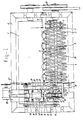
- Figure 1 shows a plan view of an alignment and peeling machine.
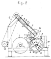
- Figure 2 shows a front view of this machine from the left-hand side in Figure 1.
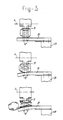
- Figure 3 shows successively three different positions of the pop-out mechanism for the popping of the onions out of the outermost skins.
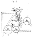
- Figure 4 shows a front view of an alternative embodiment of means for the removal from the alignment machine and oriented presentation of the onions to the subsequent processing appliances.
- Figure 5 shows a side view along the line V-V in Figure 4.
- Figure 6 shows a plan view of a transfer mechanism of the embodiment according to Figures 4 and 5.
- The onion peeling machine shown in Figures 1 to 3 incl. comprises, a) an alignment mechanism for orienting the onions into the processing position, b) means of heat treatment for loosening the outermost skins of the onions, c) a cutting mechanism for the removal of top and root end of the oriented onions, and d) a pop-out mechanism for popping or shooting out the onions axially from the outermost skins.
- The invention is concerned in the first place with the alignment mechanism. This mechanism brings the onions into a well oriented position in which the further operations can be carried out without problems. Examples of the operations are the said removal of top and root ends, and the popping of the onions axially out of the outermost skins. It must be emphasised that other facilities may also follow the alignment mechanism, for example a mechanism for notching the onions around the circumference and removing them in the radial direction from the divided outer skins or a mechanism for cutting the onions into slices. In other words, the alignment appliance now to be described can be used in conjunction with any known mechanism for which aligned presentation to the mechanism is essential for a good operation.
- The alignment mechanism consists of a closed roller 1 and a helical roller formed by two
helical rods plates 5 with a mutually adjustable axial spacing, the spacing thereof being capable of being altered by thescrew bolt 6. The closed roller 1 and thehelical roller 2, are mounted next to each other in aframe 7. They are driven by belts or chains 8 which lead to a common motor (not shown). The direction of rotation of the roller 1 and thehelical rollers rollers - The onions to be peeled are fed through a feed mechanism (not shown) in the direction of the arrow into the gap between the solid roller 1 and the
helical roller helical roller - The circumferential velocity of the solid roller is chosen somewhat larger than that of the helical roller, which is beneficial but not necessary for orienting the onions in a manner such that top and root end extends parallel to the axial direction of the roller.
- Near the gap between the solid roller and the helical roller there extends a
pipe 9 provided with openings for the supplying of steam to the onions. The helical roller transports the aligned onions to the cutting mechanism, and during this transport the onions are subjected to the influence of the steam. The outermost fleshy skin is softened as a result of this so that the flesh inside the said soft skin can easily be released therefrom. The residence time of the onions in the steam is, for example, 30 seconds. The possibility is not excluded that the onions are subjected to the heat treatment before they are fed to the aligning, cutting and popping out mechanism. Certain onions on the whole do not require to be subjected to a heat treatment. - Between the
helices helix 10 which prevents the onions landing on the unintended points between the helices. The reasons for this is that there must be some distance between the aligned onions to avoid overlapping. In the event that the alignment appliance has only to be suitable for onions of a particular size and adjustment is not required, instead of thespirals 2, and 10 a single tube may be used in which a helical groove is provided. A helically wound. strip also gives the same alignment effect. - By aligning the onions between the outer surface of the
helices - At the end of the
helices 2, 3 a scooping up mechanism may be fitted consisting of a pushingstrip 11 which is mounted on thefinal plate 5 and to which two carrier pins 12 are welded at a mutual distance. As is evident in particular from Figure 2, in the case ofrotating spirals helical roller - This mechanism comprises two
circular knives bearing arm - Each of the arms is linked by a
hinge arm plate 23. Stopelements 30 determine the minimum distance between thearms - To each
arm 17 or 18 apilot pin mechanism arms springs knives motor 28 viabelts 26 andchains 27 cut off the top and root end of the onion. - The onion is pushed by the assembly of pushing
strip 11 and carrier pins 12 to a pop-out mechanism. This comprises anelastic strip 31, consisting, for example, of a stiff rubber or spring steel covered with a rubber layer, mounted on asupport 29. An onion which is located between the pushingstrip 11 and theelastic strip 31 deflected to some extent and pretreated outer skins are gripped by the rough surface of the strip reacts to the pressure exerted by the onion popping out sideways from the outermost skins in the axial direction, and this is illustrated in Figure 3. - The
strip 31 may be a spring-load stiff pivoting strip. To prevent thestrips - The peeled onions which have popped out land in a box or in a removal transporter not shown while the outermost skins fall into a wase box.
- It is of importance that the onions introduced in the correct position by the alignment mechanism are displaced by means of the system consisting of the pushing strip and carrier pins without the centre line of the onions taking up a different direction.
- The embodiment shown with an
elastic strip 31 is simple and cheap. The pop-out principle can, however, be applied in many kinds of ways. Known mechanisms for the removal of the outermost skins may also follow the alignment appliance, for example a mechanism in which a circumferential cut in the outermost skins is applied with a knife and the onions are driven out of the incised skins in the radial direction (see for example the UK Patent Specification 821,315). - It is usually preferable that the onion is exposed to steam or heat treatment before the top and root end are cut off it. The cutting surfaces will then not be impaired. Instead of subjecting the onions to a steam treatment, flame treatment may be used. The possibility exists of carrying out the steam or heat treatment beforehand, i.e. outside the machine described.
- In the alternative embodiment according to Figures 4, 5 and 6, there is fitted above the gap between the helical construction grooved
roller spindle 40, to be driven in a rotary manner, which is provided with two fingers 41 situated close to each other which moves an onion from the gap between the roller 1 and theconstruction gripping jaw mechanism 42. This comprises aspindle 43, to be driven in a rotary manner, a piece 44 mounted thereon, two pairs ofpins 45 permanently mounted on the piece 44 and two pairs of pivotable, hooked-shapedpins 46 mounted on the piece 44. By means of hydraulic orpneumatic cylinders 47 thepins 46 can be brought into an open position or a closed gripping position with respect to thepins 45. The gripping position is indicated in Figure 4 at the top and bottom of the rotation path by full lines, while the open position (mutual angle between thepins cylinders 47 takes place by means of microswitches (not shown) which react to certain positions of the rotating piece 44. The synchronisation of the rotary movements of thespindles 40 and 43 (spindle 40 rotates twice as fast as spindle 43) is such that at the moment when theopen jaw helical construction knives knives transfer mechanism 50 consisting of twolevers spindles 54, 55 being perpendicular to therotation spindle 53. Between thelevers hydraulic cylinder 56 which can pivot the levers away from each other or towards each other. At the end of each lever agripping disc levers spindle 53 rotates with twice the speed of thespindle 43. The directions of rotation of thespindles cylinders spindles jaw discs spindle 53. The directions of rotation are always indicated by arrows. - The onion gripped between the
discs levers - It will be clear that within the scope of the claims various modifications of the machine shown and described are possible.
Claims (11)
Priority Applications (1)
| Application Number | Priority Date | Filing Date | Title |
|---|---|---|---|
| AT85201416T ATE38928T1 (en) | 1984-09-06 | 1985-09-06 | DEVICE FOR ALIGNING ONIONS OR OTHER PLANTS. |
Applications Claiming Priority (2)
| Application Number | Priority Date | Filing Date | Title |
|---|---|---|---|
| NL8402721 | 1984-09-06 | ||
| NL8402721A NL8402721A (en) | 1984-09-06 | 1984-09-06 | METHOD AND APPARATUS FOR PEELING ONIONS. |
Publications (3)
| Publication Number | Publication Date |
|---|---|
| EP0174697A2 EP0174697A2 (en) | 1986-03-19 |
| EP0174697A3 EP0174697A3 (en) | 1986-07-16 |
| EP0174697B1 true EP0174697B1 (en) | 1988-11-30 |
Family
ID=19844425
Family Applications (1)
| Application Number | Title | Priority Date | Filing Date |
|---|---|---|---|
| EP85201416A Expired EP0174697B1 (en) | 1984-09-06 | 1985-09-06 | Appliance for the alignment of onions or other vegatable bulbs |
Country Status (5)
| Country | Link |
|---|---|
| US (1) | US4730554A (en) |
| EP (1) | EP0174697B1 (en) |
| AT (1) | ATE38928T1 (en) |
| DE (1) | DE3566490D1 (en) |
| NL (1) | NL8402721A (en) |
Families Citing this family (17)
| Publication number | Priority date | Publication date | Assignee | Title |
|---|---|---|---|---|
| NL8800250A (en) * | 1988-02-02 | 1989-09-01 | Inst Voor Bewaring | Apparatus for peeling onions or other bulbous or tuberous plants. |
| DK158825C (en) * | 1988-02-16 | 1990-12-17 | Baehnckes Delikatessefabrikker | PROCEDURE AND APPARATUS FOR CUTTING THE TOP AND ROOT ON LAY |
| US4831924A (en) * | 1988-04-21 | 1989-05-23 | Ashlock Company, A Division Of Vistan Corporation | Apparatus for aligning articles |
| WO1990004337A1 (en) * | 1988-10-25 | 1990-05-03 | Robert Gough | Peeling machine |
| JP2938109B2 (en) * | 1990-01-23 | 1999-08-23 | 株式会社長岡精機製作所 | Bulb slitting machine |
| US5335792A (en) * | 1992-02-21 | 1994-08-09 | Carter Day International, Inc. | Grain separator |
| US5439674A (en) * | 1992-08-14 | 1995-08-08 | Osi Specialties, Inc. | Hair cosmetic material |
| DE4335537C2 (en) * | 1993-10-19 | 1995-07-27 | Guenter Iwanek | Device for uprooting flower bulbs |
| US5780088A (en) * | 1997-01-17 | 1998-07-14 | David R. Zittel | Electric motor driven abrasive roller peeler and cleaning machine |
| GB9804833D0 (en) | 1998-03-07 | 1998-04-29 | Rose David | Improvements in alignment techniques |
| WO2003073875A1 (en) * | 2002-03-06 | 2003-09-12 | Richard Wilkinson | Industrial onion peeler |
| US7007449B2 (en) * | 2003-03-31 | 2006-03-07 | Duane Kido | Onion harvester with leaf topper |
| US7029393B2 (en) * | 2003-08-06 | 2006-04-18 | Carter Day International, Inc. | Split inlet seal for grain separators and method |
| WO2005081890A2 (en) * | 2004-02-20 | 2005-09-09 | Henry James D | Archimedean conveyors and combustion engines |
| US7862412B2 (en) * | 2008-06-20 | 2011-01-04 | Carter Day International, Inc. | Seal assemblies for grain separators |
| JP6347715B2 (en) * | 2014-10-06 | 2018-06-27 | 株式会社ニシザワ | Onion leaf / root continuous excision machine |
| JP7118832B2 (en) * | 2018-09-18 | 2022-08-16 | 株式会社クボタ | Conveying device and preparation device for headed vegetables |
Family Cites Families (16)
| Publication number | Priority date | Publication date | Assignee | Title |
|---|---|---|---|---|
| NL90260C (en) * | ||||
| US1581071A (en) * | 1922-02-23 | 1926-04-13 | Mark W Lowe | Tomato washing, scalding, and peeling machine |
| US2332093A (en) * | 1940-04-01 | 1943-10-19 | Mark W Lowe | Conveyer for fruits and vegetables |
| GB821315A (en) * | 1955-10-03 | 1959-10-07 | Edward Sidney Manwaring Wade | Improved method and means for trimming vegetable bulbs, such as onions |
| DE2346191A1 (en) * | 1972-09-21 | 1974-03-28 | Vogelaar Matthijs Pieter | DEVICE FOR AUTOMATIC PROCESSING OF ONION AND TUBER GROWS |
| NL7513320A (en) * | 1975-11-13 | 1977-05-17 | Catharinus Sinke | Mechanical peeling of onions - with minimal damage and no removal of useful flesh |
| SE436417B (en) * | 1977-05-10 | 1984-12-10 | Plm Ab | WASTE TRANSMISSION DEVICE |
| US4237782A (en) * | 1978-11-27 | 1980-12-09 | Starr, Incorporated | Vegetable processing machine with product mobilizer apparatus |
| US4476778A (en) * | 1980-07-21 | 1984-10-16 | Spring Gully Pickles Pty, Limited | Onion peeling |
| US4355572A (en) * | 1981-04-13 | 1982-10-26 | Imdec S.R.L. | Apparatus for separating the pulp from the skin of fruit such as tomatoes |
| JPS5978676A (en) * | 1982-10-25 | 1984-05-07 | Ogawa Conveyor Kk | Method and apparatus for peeling onion |
| JPS5948987B2 (en) * | 1982-11-19 | 1984-11-30 | 小川コンベヤ株式会社 | Onion peeling device |
| US4481875A (en) * | 1982-12-03 | 1984-11-13 | M.G.I. Co., Ltd. | Bulb peeling apparatus |
| NL8300221A (en) * | 1983-01-21 | 1984-08-16 | North Invest Finance | INDUSTRIAL ONION PEELER. |
| US4470345A (en) * | 1983-04-26 | 1984-09-11 | Hiroyuki Miyata | Apparatus for peeling skins off the bulbs of onions |
| US4527438A (en) * | 1983-09-28 | 1985-07-09 | Cortex Research Corporation | Automatic feed system for sampling apparatus |
-
1984
- 1984-09-06 NL NL8402721A patent/NL8402721A/en not_active Application Discontinuation
-
1985
- 1985-09-05 US US06/772,853 patent/US4730554A/en not_active Expired - Fee Related
- 1985-09-06 EP EP85201416A patent/EP0174697B1/en not_active Expired
- 1985-09-06 DE DE8585201416T patent/DE3566490D1/en not_active Expired
- 1985-09-06 AT AT85201416T patent/ATE38928T1/en not_active IP Right Cessation
Also Published As
| Publication number | Publication date |
|---|---|
| US4730554A (en) | 1988-03-15 |
| ATE38928T1 (en) | 1988-12-15 |
| EP0174697A3 (en) | 1986-07-16 |
| NL8402721A (en) | 1986-04-01 |
| EP0174697A2 (en) | 1986-03-19 |
| DE3566490D1 (en) | 1989-01-05 |
Similar Documents
| Publication | Publication Date | Title |
|---|---|---|
| EP0174697B1 (en) | Appliance for the alignment of onions or other vegatable bulbs | |
| US2716776A (en) | Shrimp processing apparatus | |
| US2376526A (en) | Continuous peach pitter | |
| EP0115669B1 (en) | Method of and apparatus for processing squid | |
| EP3518682A1 (en) | Shrimp peeling station comprising a rotor with a rotatable gripper | |
| US5545422A (en) | Peeling apparatus and method | |
| US4534085A (en) | Fish filleting system | |
| US3075634A (en) | Machine for handling artichokes | |
| CA1306171C (en) | Method and apparatus for pretreating and debarking logs | |
| US3696848A (en) | Method and apparatus for removing skin from onions or like vegetables | |
| EP0327146B1 (en) | Device for peeling onions or other bulbous or tuberous plants | |
| US4068011A (en) | Method of peeling onions by scalding and cutting | |
| US3744408A (en) | Coconut paring machine | |
| US4202261A (en) | Method and apparatus for trimming onions or like produce | |
| GB2077577A (en) | Apparatus for peeling crops, such as bulbs or tubers | |
| US3017298A (en) | Tomato peeling method | |
| US2375350A (en) | Fruit handling machine | |
| US2888969A (en) | Tomato peeling machine | |
| US6220153B1 (en) | Automated peeler for fruit products | |
| US3606917A (en) | Peeling machine | |
| US3894810A (en) | Coconut paring process | |
| US3282314A (en) | Drupe pitting method and apparatus including segregating means for pitted and unpitted fruit | |
| US2239013A (en) | Fish cleaning and cutting machine | |
| US3378050A (en) | Apparatus for coordinating a fruit processing machine | |
| US3102568A (en) | Method of pitting peaches |
Legal Events
| Date | Code | Title | Description |
|---|---|---|---|
| PUAI | Public reference made under article 153(3) epc to a published international application that has entered the european phase |
Free format text: ORIGINAL CODE: 0009012 |
|
| AK | Designated contracting states |
Kind code of ref document: A2 Designated state(s): AT BE CH DE FR GB IT LI LU NL SE |
|
| PUAL | Search report despatched |
Free format text: ORIGINAL CODE: 0009013 |
|
| AK | Designated contracting states |
Kind code of ref document: A3 Designated state(s): AT BE CH DE FR GB IT LI LU NL SE |
|
| 17P | Request for examination filed |
Effective date: 19860714 |
|
| 17Q | First examination report despatched |
Effective date: 19870924 |
|
| GRAA | (expected) grant |
Free format text: ORIGINAL CODE: 0009210 |
|
| AK | Designated contracting states |
Kind code of ref document: B1 Designated state(s): AT BE CH DE FR GB IT LI LU NL SE |
|
| REF | Corresponds to: |
Ref document number: 38928 Country of ref document: AT Date of ref document: 19881215 Kind code of ref document: T |
|
| ITF | It: translation for a ep patent filed | ||
| REF | Corresponds to: |
Ref document number: 3566490 Country of ref document: DE Date of ref document: 19890105 |
|
| ET | Fr: translation filed | ||
| PLBE | No opposition filed within time limit |
Free format text: ORIGINAL CODE: 0009261 |
|
| STAA | Information on the status of an ep patent application or granted ep patent |
Free format text: STATUS: NO OPPOSITION FILED WITHIN TIME LIMIT |
|
| 26N | No opposition filed | ||
| ITTA | It: last paid annual fee | ||
| PGFP | Annual fee paid to national office [announced via postgrant information from national office to epo] |
Ref country code: GB Payment date: 19920825 Year of fee payment: 8 |
|
| PGFP | Annual fee paid to national office [announced via postgrant information from national office to epo] |
Ref country code: FR Payment date: 19920909 Year of fee payment: 8 |
|
| PGFP | Annual fee paid to national office [announced via postgrant information from national office to epo] |
Ref country code: AT Payment date: 19920910 Year of fee payment: 8 |
|
| PGFP | Annual fee paid to national office [announced via postgrant information from national office to epo] |
Ref country code: SE Payment date: 19920914 Year of fee payment: 8 |
|
| PGFP | Annual fee paid to national office [announced via postgrant information from national office to epo] |
Ref country code: CH Payment date: 19920918 Year of fee payment: 8 |
|
| PGFP | Annual fee paid to national office [announced via postgrant information from national office to epo] |
Ref country code: DE Payment date: 19920923 Year of fee payment: 8 |
|
| PGFP | Annual fee paid to national office [announced via postgrant information from national office to epo] |
Ref country code: BE Payment date: 19921028 Year of fee payment: 8 |
|
| PGFP | Annual fee paid to national office [announced via postgrant information from national office to epo] |
Ref country code: LU Payment date: 19921204 Year of fee payment: 8 |
|
| EPTA | Lu: last paid annual fee | ||
| PG25 | Lapsed in a contracting state [announced via postgrant information from national office to epo] |
Ref country code: LU Free format text: LAPSE BECAUSE OF NON-PAYMENT OF DUE FEES Effective date: 19930906 Ref country code: GB Effective date: 19930906 Ref country code: AT Effective date: 19930906 |
|
| PG25 | Lapsed in a contracting state [announced via postgrant information from national office to epo] |
Ref country code: SE Effective date: 19930907 |
|
| PG25 | Lapsed in a contracting state [announced via postgrant information from national office to epo] |
Ref country code: LI Effective date: 19930930 Ref country code: CH Effective date: 19930930 Ref country code: BE Effective date: 19930930 |
|
| PGFP | Annual fee paid to national office [announced via postgrant information from national office to epo] |
Ref country code: NL Payment date: 19930930 Year of fee payment: 9 |
|
| BERE | Be: lapsed |
Owner name: INSTITUUT VOOR BEWARING EN VERWERKING VAN LANDBOU Effective date: 19930930 |
|
| GBPC | Gb: european patent ceased through non-payment of renewal fee |
Effective date: 19930906 |
|
| PG25 | Lapsed in a contracting state [announced via postgrant information from national office to epo] |
Ref country code: FR Free format text: LAPSE BECAUSE OF NON-PAYMENT OF DUE FEES Effective date: 19940531 |
|
| REG | Reference to a national code |
Ref country code: CH Ref legal event code: PL |
|
| PG25 | Lapsed in a contracting state [announced via postgrant information from national office to epo] |
Ref country code: DE Effective date: 19940601 |
|
| REG | Reference to a national code |
Ref country code: FR Ref legal event code: ST |
|
| EUG | Se: european patent has lapsed |
Ref document number: 85201416.6 Effective date: 19940410 |
|
| PG25 | Lapsed in a contracting state [announced via postgrant information from national office to epo] |
Ref country code: NL Effective date: 19950401 |
|
| NLV4 | Nl: lapsed or anulled due to non-payment of the annual fee |