EP0326847A2 - Übertragungsstrecke für optische Strahlung und deren Anwendungen - Google Patents
Übertragungsstrecke für optische Strahlung und deren Anwendungen Download PDFInfo
- Publication number
- EP0326847A2 EP0326847A2 EP89100713A EP89100713A EP0326847A2 EP 0326847 A2 EP0326847 A2 EP 0326847A2 EP 89100713 A EP89100713 A EP 89100713A EP 89100713 A EP89100713 A EP 89100713A EP 0326847 A2 EP0326847 A2 EP 0326847A2
- Authority
- EP
- European Patent Office
- Prior art keywords
- transmission
- optical fiber
- link according
- transmission link
- silicon dioxide
- Prior art date
- Legal status (The legal status is an assumption and is not a legal conclusion. Google has not performed a legal analysis and makes no representation as to the accuracy of the status listed.)
- Withdrawn
Links
- 230000005855 radiation Effects 0.000 title claims abstract description 26
- 230000003287 optical effect Effects 0.000 title claims abstract description 17
- 230000005540 biological transmission Effects 0.000 claims abstract description 48
- VYPSYNLAJGMNEJ-UHFFFAOYSA-N Silicium dioxide Chemical compound O=[Si]=O VYPSYNLAJGMNEJ-UHFFFAOYSA-N 0.000 claims abstract description 37
- 239000013307 optical fiber Substances 0.000 claims abstract description 27
- 235000012239 silicon dioxide Nutrition 0.000 claims abstract description 16
- 239000000377 silicon dioxide Substances 0.000 claims abstract description 16
- 239000000835 fiber Substances 0.000 claims abstract description 9
- 229910052810 boron oxide Inorganic materials 0.000 claims abstract description 7
- JKWMSGQKBLHBQQ-UHFFFAOYSA-N diboron trioxide Chemical compound O=BOB=O JKWMSGQKBLHBQQ-UHFFFAOYSA-N 0.000 claims abstract description 7
- PXGOKWXKJXAPGV-UHFFFAOYSA-N Fluorine Chemical compound FF PXGOKWXKJXAPGV-UHFFFAOYSA-N 0.000 claims abstract description 6
- 229910052731 fluorine Inorganic materials 0.000 claims abstract description 6
- 239000011737 fluorine Substances 0.000 claims abstract description 6
- 239000000463 material Substances 0.000 claims abstract description 5
- 238000005516 engineering process Methods 0.000 claims abstract description 4
- 238000004611 spectroscopical analysis Methods 0.000 claims abstract description 3
- 238000005253 cladding Methods 0.000 claims abstract 2
- 238000001816 cooling Methods 0.000 claims description 8
- 238000010521 absorption reaction Methods 0.000 claims description 7
- IJGRMHOSHXDMSA-UHFFFAOYSA-N Atomic nitrogen Chemical compound N#N IJGRMHOSHXDMSA-UHFFFAOYSA-N 0.000 claims description 6
- 239000002826 coolant Substances 0.000 claims description 5
- 239000002019 doping agent Substances 0.000 claims description 3
- 239000012535 impurity Substances 0.000 claims description 3
- 239000011810 insulating material Substances 0.000 claims description 3
- 239000007788 liquid Substances 0.000 claims description 3
- 229910021645 metal ion Inorganic materials 0.000 claims description 3
- 238000000034 method Methods 0.000 claims description 3
- 229910052757 nitrogen Inorganic materials 0.000 claims description 3
- 230000008569 process Effects 0.000 claims description 3
- 238000001311 chemical methods and process Methods 0.000 abstract description 3
- 239000003814 drug Substances 0.000 abstract description 2
- 238000004519 manufacturing process Methods 0.000 description 3
- 239000004033 plastic Substances 0.000 description 3
- 230000006378 damage Effects 0.000 description 2
- 239000007789 gas Substances 0.000 description 2
- 238000002161 passivation Methods 0.000 description 2
- 230000009467 reduction Effects 0.000 description 2
- 239000004065 semiconductor Substances 0.000 description 2
- 201000004681 Psoriasis Diseases 0.000 description 1
- 238000006243 chemical reaction Methods 0.000 description 1
- 210000004087 cornea Anatomy 0.000 description 1
- 230000008878 coupling Effects 0.000 description 1
- 238000010168 coupling process Methods 0.000 description 1
- 238000005859 coupling reaction Methods 0.000 description 1
- 230000003247 decreasing effect Effects 0.000 description 1
- 230000008021 deposition Effects 0.000 description 1
- 239000002657 fibrous material Substances 0.000 description 1
- 238000010438 heat treatment Methods 0.000 description 1
- 230000006872 improvement Effects 0.000 description 1
- 239000004922 lacquer Substances 0.000 description 1
- 238000005259 measurement Methods 0.000 description 1
- TWNQGVIAIRXVLR-UHFFFAOYSA-N oxo(oxoalumanyloxy)alumane Chemical compound O=[Al]O[Al]=O TWNQGVIAIRXVLR-UHFFFAOYSA-N 0.000 description 1
- 238000006552 photochemical reaction Methods 0.000 description 1
- 239000002985 plastic film Substances 0.000 description 1
- 229920006255 plastic film Polymers 0.000 description 1
- 230000003595 spectral effect Effects 0.000 description 1
- 238000004659 sterilization and disinfection Methods 0.000 description 1
- 239000000126 substance Substances 0.000 description 1
- 239000000758 substrate Substances 0.000 description 1
- 230000001960 triggered effect Effects 0.000 description 1
Images
Classifications
-
- G—PHYSICS
- G02—OPTICS
- G02B—OPTICAL ELEMENTS, SYSTEMS OR APPARATUS
- G02B6/00—Light guides; Structural details of arrangements comprising light guides and other optical elements, e.g. couplings
- G02B6/10—Light guides; Structural details of arrangements comprising light guides and other optical elements, e.g. couplings of the optical waveguide type
- G02B6/102—Light guides; Structural details of arrangements comprising light guides and other optical elements, e.g. couplings of the optical waveguide type for infrared and ultraviolet radiation
-
- G—PHYSICS
- G02—OPTICS
- G02B—OPTICAL ELEMENTS, SYSTEMS OR APPARATUS
- G02B6/00—Light guides; Structural details of arrangements comprising light guides and other optical elements, e.g. couplings
- G02B6/44—Mechanical structures for providing tensile strength and external protection for fibres, e.g. optical transmission cables
- G02B6/4439—Auxiliary devices
Definitions
- the invention relates to a transmission path for optical radiation, which has at least one optical fiber, the core of which consists of glassy, synthetic silicon dioxide of high purity with respect to metal ion impurities and the jacket of glassy, with boron oxide and / or fluorine-doped synthetic silicon dioxide .
- the invention also relates to applications of such transmission links.
- optical fibers are known with a core made of pure silicon dioxide and a sheath consisting of silicon dioxide doped with boron oxide or fluorine.
- EP-OS 0 173 183 discloses optical fibers with a core made of pure, synthetic OH-containing quartz glass and a jacket made of quartz glass doped with fluorine and boron oxide.
- Optical fibers of the previously known type are well suited in a transmission path for optical radiation if the optical radiation is in a wavelength range above 300 nm. It has been found that the known optical fibers are less suitable for transmission links with lengths of more than 10 m if the wavelength of the optical radiation to be transmitted is less than 300 nm, that is to say in the short-wave ultraviolet spectral range. For wavelengths below 300 nm, there is a noticeable absorption of the optical radiation, which increases with decreasing wavelength. The known optical fibers become practically opaque for wavelengths below about 190 nm when they are used in a transmission path that is a few meters long.
- the object of the invention is therefore to provide a transmission path for optical radiation with wavelengths in the range from approximately 160 to 300 nm.
- This object is achieved according to the invention for a transmission link of the type characterized in the introduction in that for the transmission of optical radiation with a wavelength in the range from approximately 160 to 300 nm the optical fiber is cooled to a temperature below 220 K essentially over its entire length.
- This measure surprisingly has the consequence that the transmission increases to twice the value up to 10 times the value compared to the uncooled fiber.
- the absorption edge of the transmission link according to the invention is shifted to shorter wavelengths, so that it is possible to transmit radiation of shorter wavelengths than hitherto than with optical fibers which are at room temperature.
- the reduction in the absorption of the fiber material by cooling not only causes an increase in the transmission.
- the lower heating also increases the threshold for the thermal destruction of the fiber.
- the optical fiber is advantageously enclosed in a cover made of heat-insulating material.
- the casing is designed as a cooling jacket and it has a connection for the supply and a connection for the discharge of a coolant.
- the optical fiber is preferably cooled with liquid nitrogen which is passed through the cooling jacket.
- a short piece of fiber is advantageously led out of the casing without cooling. This improves the mobility of the coupling of the transmission link at the place of use.
- the invention has not only proven itself for optical fibers with a core made of glassy synthetic silicon dioxide and a jacket made of glassy synthetic silicon dioxide doped with boron oxide and / or fluorine, but also for those optical fibers in which the core is made of glassy, synthetic, doped There is silicon dioxide, the dopants not or only slightly influencing the ultraviolet absorption. Fluorine, boron oxide and / or aluminum oxide, for example, are suitable as such dopants.
- a transmission link according to the invention is preferably used wherever high UV light outputs are to be conducted from a light source, such as a gas discharge lamp or laser, to a place of use, that is to say in material processing, for medical and biological applications and for chemical processes.
- a light source such as a gas discharge lamp or laser
- the transmission of UV radiation through a light pipe offers the following advantages: The risk potential of the light source can be reduced and several locations can be supplied from one source.
- the use is also advantageous in spectroscopy for connecting a spectrometer to a detector.
- measurements can be carried out at wavelengths at which uncooled transmission links fail.
- the transmission path according to the invention can be used to evaporate parts of a plastic film that has been applied to an integrated circuit for passivation by means of pulsed, short-wave ultraviolet radiation from an excimer laser.
- the transmission link according to the invention can also be used for the production of very fine structures in semiconductor technology by means of photochemical reactions in ultraviolet-sensitive lacquer layers.
- the transmission link according to the invention can be used in ophthalmology, for example to make the finest cuts for correcting the shape of the cornea of the eye using short-wave ultraviolet laser radiation.
- the treatment of psoriasis with ultraviolet radiation with a wavelength in the range from 270 nm to 300 nm can also be mentioned as an application example for the transmission link according to the invention.
- the transmission link according to the invention for air and surface disinfection by means of ultraviolet radiation in the wavelength range between 250 nm and 300 nm could be used.
- an example of the use of the transmission link according to the invention in chemical process engineering is the production of dielectric insulating or passivation layers from silicon dioxide in semiconductor technology by deposition from the gas phase, the reactions of the gaseous or vaporous substances by means of photochemical processes using ultraviolet Radiation are triggered.
- the silicon dioxide layers can thus be deposited at relatively low substrate temperatures up to 50 ° C.
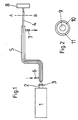
- a beam 2 of the optical radiation to be transmitted is fed from a radiation source 1 into one end of the optical fiber 4 by means of a quartz glass lens 3 and is emitted to an object 8 to be irradiated at the other end.
- the optical fiber is surrounded by a sheath 5 made of heat-insulating material, which in this exemplary embodiment is designed as a cooling jacket which is provided with a supply nozzle 6 and an outlet nozzle 7 for the coolant.
- the entire length of the optical fiber is not enclosed by the cooling jacket, but rather it is uncooled at the end emitting the optical radiation, which is adjacent to the object 8 to be irradiated.
- FIG. 1 the entire length of the optical fiber is not enclosed by the cooling jacket, but rather it is uncooled at the end emitting the optical radiation, which is adjacent to the object 8 to be irradiated.
- the optical fiber consists of a core 9, a jacket 10 and a plastic sheath 11.
- the core 9 consists of glassy, synthetic silicon dioxide of high purity with regard to metal ion impurities.
- the jacket consists of fluorine-doped, synthetic silicon dioxide.
- the plastic cover prevents micro-kinking losses of the fiber and damage to the fiber surface.
- the diameter of the core 9 of the optical fiber is 500 ⁇ m; Usual core diameters are in the range from 2 to 1000 ⁇ m.
- the thickness of the jacket 10 is 20 microns; The jacket thickness is usually in the range from 10 to 50 ⁇ m.
- the thickness of the plastic sleeve 11 was 5 ⁇ m in the exemplary embodiment; Typical thicknesses are in the range from 5 to 100 ⁇ m.
- the length of the transmission path depends on the wavelength. For very short wavelengths, i.e. in the range below 200 nm, the length of the transmission path is approximately 0.5 m to 3 m. In the range from 200 to 300 nm, the transmission path can be more than 15 m.
Landscapes
- Physics & Mathematics (AREA)
- General Physics & Mathematics (AREA)
- Optics & Photonics (AREA)
- Health & Medical Sciences (AREA)
- Toxicology (AREA)
- Glass Compositions (AREA)
- Optical Fibers, Optical Fiber Cores, And Optical Fiber Bundles (AREA)
Abstract
Description
- Die Erfindung bezieht sich auf eine Übertragungsstrecke für optische Strahlung, die wenigstens eine optische Faser aufweist, deren Kern aus glasigem, synthetischem Siliziumdioxid hoher Reinheit in Bezug auf Metallionen-Verunreinigungen und deren Mantel aus glasigem, mit Boroxid und/oder Fluor dotiertem, synthetischem Siliziumdioxid besteht.
Außerdem bezieht sich die Erfindung auf Anwendungen derartiger Übertragungsstrecken. - Aus der DE-PS 25 36 457 ist ein verfahren zur Herstellung von synthetischem, OH-Ionen-freiem mit Fluor dotiertem Quarzglas bekannt, das als Mantelwerkstoff für optische Fasern mit einem Kern aus synthetischem Quarzglas dient.
- Aus der FR-OS 22 08 127 sind optische Fasern bekannt mit einem Kern aus reinem Siliziumdioxid und einem Mantel, der aus mit Boroxid oder Fluor dotiertem Siliziumdioxid besteht.
- Schließlich sind aus der EP-OS 0 173 183 optische Fasern bekannt mit einem Kern aus reinem, synthetischem OH-haltigem Quarzglas und einem Mantel aus mit Fluor und Boroxid dotiertem Quarzglas.
- Optische Fasern der vorbekannten Art eignen sich gut in einer Übertragungsstrecke für optische Strahlung, wenn die optische Strahlung in einem Wellenlängenbereich oberhalb 300 nm liegt. Es wurde festgestellt, daß die bekannten optischen Fasern sich weniger für Übertragungsstrecke mit Längen über 10 m eignen, wenn die Wellenlänge der zu übertragenden optischen Strahlung weniger als 300 nm beträgt, also im kurzwelligen ultravioletten Spektralbereich liegt. Für Wellenlängen unterhalb 300 nm setzt eine merkliche Absorption der optischen Strahlung ein, die sich mit abnehmender Wellenlänge noch verstärkt. Für Wellenlängen unterhalb von etwa 190 nm werden die bekannten optischen Fasern praktisch undurchlässig, wenn sie in einer Übertragungsstrecke eingesetzt werden, die einige Meter lang ist.
- Die Erfindung hat sich daher die Aufgabe gestellt, eine Übertragungsstrecke für optische Strahlung mit Wellenlängen im Bereich von etwa 160 bis 300 nm bereitzustellen.
- Gelöst wird diese Aufgabe für eine Übertragungsstrecke der eingangs charakterisierten Art erfindungsgemäß dadurch, daß zur Übertragung von optischer Strahlung mit einer Wellenlänge im Bereich von etwa 160 bis 300 nm die optische Faser im wesentlichen über ihre gesamte Länge auf eine Temperatur unterhalb von 220 K gekühlt ist. Diese Maßnahme hat überraschenderweise zur Folge, daß die Transmission auf den doppelten Wert bis über 10-fachen Wert im Vergleich zur ungekühlten Faser ansteigt. Außerdem wurde beobachtet, daß die Absorptionskante der erfindungsgemäßen Übertragungsstrecke zu kürzeren Wellenlängen verschoben ist, so daß es möglich ist, Strahlung kürzerer Wellenlänge als bisher zu übertragen als mit optischen Fasern, die sich auf Zimmertemperatur befinden. Die Verminderung der Absorption des Fasermaterials durch Kühlung bewirkt nicht nur eine Erhöhung der Transmission. Durch die geringere Aufheizung wird auch der Schwellwert für die thermische Zerstörung der Faser erhöht.
- Die optische Faser ist vorteilhafterweise mit einer Hülle aus wärmeisolierendem Werkstoff umschlossen. In einer vorteilhaften Ausführungsform ist die Hülle als Kühlmantel ausgebildet und sie besitzt einen Anschluß für die Zufuhr und einen Anschluß für die Ableitung eines Kühlmittels. Vorzugsweise wird die optische Faser mit flüssigem Stickstoff gekühlt, der durch den Kühlmantel hindurchgeleitet wird.
- Am Austrittsende der optischen Strahlung aus der Faser ist vorteilhafterweise ein kurzes Faserstück ungekühlt aus der Hülle herausgeführt. Hierdurch wird die Beweglichkeit des Ankoppelns der Übertragungsstrecke am Einsatzort verbessert.
- Die Erfindung hat sich nicht nur bewährt für optische Fasern mit einem Kern aus glasigem synthetischem Siliziumdioxid und einem Mantel aus glasigem, mit Boroxid und/oder Fluor dotiertem synthetischen Siliziumdioxid, sondern auch für solche optische Fasern, bei denen der Kern aus glasigem, synthetischem, dotiertem Siliziumdioxid besteht, wobei die Dotiermittel die Ultraviolett-Absorption nicht oder nur geringfügig beeinflussen. Als derartige Dotiermittel kommen beispielsweise Fluor, Boroxid und/oder Aluminiumoxid in Frage.
- Bevorzugte Verwendung findet eine erfindungsgemäße Übertragungsstrecke überall dort, wo hohe UV-Lichtleistungen von einer Lichtquelle, wie Gasentladungslampe oder Laser, zu einem Einsatzort geleitet werden sollen, also bei der Materialbearbeitung, für medizinische und biologische Anwendungen und für chemische Prozesse. Die Übertragung der UV-Strahlung durch eine Lichtleitung bietet folgende Vorteile: Das Gefahrenpotential der Lichtquelle kann reduziert werden und es können mehrere Einsatzorte von einer Quelle aus versorgt werden.
- Auch in der Spektroskopie zur Verbindung eines Spektrometers mit einem Detektor ist der Einsatz von Vorteil. Durch die erfindungsgemäße Übertragungsstrecke können hier Messungen bei solchen Wellenlängen durchgeführt werden, bei denen ungekühlte Übertragungsstrecken versagen.
- Als bevorzugte Beispiele für die Anwendung erfindungsgemäßer Übertragungsstrecken seien folgende genannt:
Auf dem Gebiet der Materialbearbeitung kann die erfindungsgemäße Übertragungsstrecke zum Verdampfen von Teilen eines Kunststoff-Films, der zur Passivierung auf einen integrierten Schaltkreis aufgebracht wurde, mittels gepulster, kurzwelliger Ultraviolett-Strahlung eines Excimer-Lasers verwendet werden. Auch für die Herstellung sehr feiner Strukturen in der Halbleitertechnik mittels photochemischer Reaktionen in ultraviolett-empfindlicher Lackschichten ist die erfindungsgemäße Übertragungsstrecke einsetzbar. - In der Medizin ist die erfindungsgemäße Übertragungsstrecke in der Augenheilkunde einsetzbar, beispielsweise um feinste Schnitte zur Formkorrektur der Hornhaut des Auges mittels kurzwelliger ultravioletter-Laserstrahlung durchzuführen. Auch die Behandlung der Schuppenflechte (Psoriasis) mit ultravioletter Strahlung mit einer Wellenlänge im Bereich von 270 nm bis 300 nm ist als Anwendungsbeispiel für die erfindungsgemaße Übertragungsstrecke zu nennen.
- Auf biologischem Gebiet könnte die erfindungsgemäße Übertragungsstrecke zur Luft- und Flächenentkeimung mittels ultravioletter Strahlung im Wellenlängenbereich zwischen 250 nm und 300 nm eingesetzt werden.
- Schließlich sei noch als Beispiel für den Einsatz der erfindungsgemäßen Übertragungsstrecke in der chemischen Prozeßtechnik die Herstellung von dielektrischen Isolier- oder Passivierungsschichten aus Siliziiumdioxid in der Halbleitertechnik durch Niederschlagen aus der Gasphase genannt, wobei die Reaktionen der gas- bzw. dampfförmigen Stoffe durch photochemische Prozesse mittels ultravioletter Strahlung ausgelöst werden. Die Siliziumdioxidschichten lassen sich so bei relativ niedrigen Substrattemperaturen bis zu 50°C abscheiden.
- Es hat sich ergeben, daß bei einer erfindungsgemäßen Übertragungsstrecke, wenn sie mit flüssigem Stickstoff auf einen Wert von 77 K gekühlt wird, sich die Absorptionskante der optischen Faser um etwa 3 bis 5 nm zu kürzeren Wellenlängen hin verschiebt. Dies entspricht bei 170 nm einer Verminderung des Absorptionskoeffizienten von 0,5 cm⁻¹ auf etwa 0,2 cm⁻¹. Bei einer erfindungsgemäßen Übertragungsstrecke von 10 cm Länge wird dadurch die Transmission von 0,7 % auf 14 % bei 170 nm ansteigen. Für Strahlung einer Wellenlänge von 193 nm, die von einem Excimer-Laser emittiert wird, ergibt sich für eine Länge der erfindungsgemäßen Übertragungsstrecke von 1 m praktisch eine Verdoppelung der Transmission bei einer Kühlung auf 77 K. Es hat sich gezeigt, daß sich bei optischer Strahlung bei Wellenlängen im Bereich von 200 bis 300 nm die erfindungsgemäße Übertragungsstrecke noch eine merkliche Verbesserung der Transmission ergibt, insbesondere wenn die Übertragungsstreckenlängen 15 m und mehr betragen.
- In den Figuren sind Ausführungsbeispiele der Erfindung dargestellt. Es zeigen:
- Figur 1 schematisch eine erfindungsgemäße Übertragungsstrecke mit einer mit Kühlmantel zum Durchleiten eines Kühlmittels versehenen optischen Faser,
- Figur 2 einen Querschnitt durch die Faser entlang der Linie AB von Figur 1,
- Wie aus Figur 1 zu entnehmen ist, wird von einer Strahlungsquelle 1 ein Bündel 2 der zu übertragenden optischen Strahlung mittels einer Quarzglaslinse 3 in das eine Ende der optischen Faser 4 eingespeist und am anderen Ende auf ein zu bestrahlendes Objekt 8 abgegeben. Die optische Faser ist von einer Hülle 5 aus wärmeisolierendem Werkstoff umgeben, die in diesem Ausführungsbeispiel als Kühlmantel ausgebildet ist, der mit einem Zufuhrstutzen 6 und einem Abflußstutzen 7 für das Kühlmittel versehen ist. Wie aus der Figur ersichtlich, ist nicht die optische Faser über ihre Gesamtlänge von dem Kühlmantel umschlossen, sondern sie ist an dem die optische Strahlung abgebenden Ende, das dem zu bestrahlendem Objekt 8 benachbart ist, ungekühlt. Die optische Faser besteht, wie aus Figur 2 ersichtlich ist, aus einem Kern 9, einem Mantel 10 und einer Kunststoffhülle 11. Der Kern 9 besteht aus glasigem, synthetischem Siliziumdioxid hoher Reinheit in Bezug auf Metallionen-Verunreinigungen. Der Mantel besteht in dem Ausführungsbeispiel aus Fluor-dotiertem, synthetischem Siliziumdioxid. Durch die Kunststoffhülle werden Mikroknickverluste der Faser und Beschädigungen der Faseroberfläche vermieden. In dem Ausführungsbeispiel beträgt der Durchmesser des Kerns 9 der optischen Faser 500 µm; übliche Kerndurchmesser liegen im Bereich von 2 bis 1000 µm. Die Dicke des Mantels 10 beträgt 20 µm; üblicherweise liegt die Manteldicke im Bereich von 10 bis 50 µm. Die Dicke der Kunststoffhülle 11 betrug in dem Ausführungsbeispiel 5 µm; übliche Dicken liegen im Bereich von 5 bis 100 µm. Die Länge der Übertragungsstrecke ist wellenlängenabhängig. Für sehr kurze Wellenlängen, also im Bereich unterhalb von 200 nm, beträgt die Länge der Übertragungsstrecke etwa 0,5 m bis 3 m. Im Bereich von 200 bis 300 nm kann die Übertragungsstrecke mehr als 15 m betragen.
Claims (7)
Applications Claiming Priority (2)
| Application Number | Priority Date | Filing Date | Title |
|---|---|---|---|
| DE3803413 | 1988-02-05 | ||
| DE3803413A DE3803413C1 (de) | 1988-02-05 | 1988-02-05 |
Publications (2)
| Publication Number | Publication Date |
|---|---|
| EP0326847A2 true EP0326847A2 (de) | 1989-08-09 |
| EP0326847A3 EP0326847A3 (de) | 1990-10-24 |
Family
ID=6346674
Family Applications (1)
| Application Number | Title | Priority Date | Filing Date |
|---|---|---|---|
| EP19890100713 Withdrawn EP0326847A3 (de) | 1988-02-05 | 1989-01-17 | Übertragungsstrecke für optische Strahlung und deren Anwendungen |
Country Status (4)
| Country | Link |
|---|---|
| US (1) | US4915474A (de) |
| EP (1) | EP0326847A3 (de) |
| JP (1) | JPH0830769B2 (de) |
| DE (1) | DE3803413C1 (de) |
Cited By (1)
| Publication number | Priority date | Publication date | Assignee | Title |
|---|---|---|---|---|
| EP0557587A1 (de) * | 1992-02-28 | 1993-09-01 | Heraeus Quarzglas GmbH | Bauteil für die Übertragung von energiereichem Licht und Verwendung des Bauteils |
Families Citing this family (4)
| Publication number | Priority date | Publication date | Assignee | Title |
|---|---|---|---|---|
| US5300097A (en) * | 1991-02-13 | 1994-04-05 | Lerner Ethan A | Fiber optic psoriasis treatment device |
| US5459803A (en) * | 1993-02-18 | 1995-10-17 | The Furukawa Electric Co., Ltd. | Quartz-based optical fiber with a lens and its manufacturing method |
| US7457502B2 (en) * | 2004-04-01 | 2008-11-25 | The Boeing Company | Systems and methods of cooling a fiber amplifier with an emulsion of phase change material |
| US10371910B2 (en) | 2017-12-22 | 2019-08-06 | At&T Intellectual Property I, L.P. | Optical communications cables utilizing topological insulators as optical fiber cores |
Citations (4)
| Publication number | Priority date | Publication date | Assignee | Title |
|---|---|---|---|---|
| JPS56132302A (en) * | 1980-03-21 | 1981-10-16 | Fujikura Ltd | Optical fiber cable |
| JPS57185403A (en) * | 1981-05-12 | 1982-11-15 | Asahi Glass Co Ltd | Infrared ray transmitting material |
| EP0094236A1 (de) * | 1982-05-10 | 1983-11-16 | RAYCHEM CORPORATION (a California corporation) | Verfahren zur Übertragung von UV-Licht |
| EP0281222A1 (de) * | 1987-02-12 | 1988-09-07 | Stc Plc | Laser und Verstärker |
Family Cites Families (6)
| Publication number | Priority date | Publication date | Assignee | Title |
|---|---|---|---|---|
| US4165152A (en) * | 1972-11-25 | 1979-08-21 | Sumitomo Electric Industries, Ltd. | Process for producing optical transmission fiber |
| NL182310C (nl) * | 1972-11-25 | 1988-02-16 | Sumitomo Electric Industries | Glasvezel voor optische transmissie. |
| JPS589102A (ja) * | 1981-07-10 | 1983-01-19 | Agency Of Ind Science & Technol | 光学フアイバ−冷却機構 |
| JPS59174541A (ja) * | 1983-01-11 | 1984-10-03 | Hitachi Cable Ltd | 偏波面保存光フアイバ |
| US4822136A (en) * | 1984-06-15 | 1989-04-18 | Polaroid Corporation | Single mode optical fiber |
| US4733939A (en) * | 1984-08-18 | 1988-03-29 | Mitsubishi Metal Co., | Radiation-resistant optical conductor |
-
1988
- 1988-02-05 DE DE3803413A patent/DE3803413C1/de not_active Expired
- 1988-11-29 US US07/277,249 patent/US4915474A/en not_active Expired - Fee Related
-
1989
- 1989-01-17 EP EP19890100713 patent/EP0326847A3/de not_active Withdrawn
- 1989-02-02 JP JP1022770A patent/JPH0830769B2/ja not_active Expired - Fee Related
Patent Citations (4)
| Publication number | Priority date | Publication date | Assignee | Title |
|---|---|---|---|---|
| JPS56132302A (en) * | 1980-03-21 | 1981-10-16 | Fujikura Ltd | Optical fiber cable |
| JPS57185403A (en) * | 1981-05-12 | 1982-11-15 | Asahi Glass Co Ltd | Infrared ray transmitting material |
| EP0094236A1 (de) * | 1982-05-10 | 1983-11-16 | RAYCHEM CORPORATION (a California corporation) | Verfahren zur Übertragung von UV-Licht |
| EP0281222A1 (de) * | 1987-02-12 | 1988-09-07 | Stc Plc | Laser und Verstärker |
Non-Patent Citations (2)
| Title |
|---|
| PATENT ABSTRACTS OF JAPAN, Band 6, Nr. 5 (P-97)[883], 13. Januar 1982; & JP-A-56 132 302 (FUJIKURA DENSEN K.K.) 16-10-1981 * |
| PATENT ABSTRACTS OF JAPAN, Band 7, Nr. 32 (P-174)[1177], 8. Februar 1983; & JP-A-57 185 403 (ASAHI GLASS K.K.) 15-11-1982 * |
Cited By (2)
| Publication number | Priority date | Publication date | Assignee | Title |
|---|---|---|---|---|
| EP0557587A1 (de) * | 1992-02-28 | 1993-09-01 | Heraeus Quarzglas GmbH | Bauteil für die Übertragung von energiereichem Licht und Verwendung des Bauteils |
| US5315685A (en) * | 1992-02-28 | 1994-05-24 | Heraeus Quarzglas Gmbh | Component for the transmission of high-energy light, and the application of the component |
Also Published As
| Publication number | Publication date |
|---|---|
| DE3803413C1 (de) | 1989-03-30 |
| JPH01224702A (ja) | 1989-09-07 |
| US4915474A (en) | 1990-04-10 |
| JPH0830769B2 (ja) | 1996-03-27 |
| EP0326847A3 (de) | 1990-10-24 |
Similar Documents
| Publication | Publication Date | Title |
|---|---|---|
| DE69535032T2 (de) | Kohärenter, flexibler hohlfaserwellenleiter mit beschichteter innenbohrung, und dessen herstellungsverfahren | |
| DE60033481T2 (de) | Optischer Werkstoff aus Quarzglas für Excimer Laser und Excimer Lampe, und Verfahren zu dessen Herstellung | |
| EP3150562B1 (de) | Verwendung von optischem filtermaterial aus dotiertem quarzglas sowie das optische filtermaterial enthaltende uv-lampe | |
| DE69920251T2 (de) | Lichtverstärkendes glas, lichtverstärkendes mediumund harzbeschichtetes lichtverstärkendes medium | |
| EP0780707A1 (de) | Bauteil für die Übertragung energiereicher UV-Strahlung und Verfahren zur Herstellung eines solchen Bauteils und seine Verwendung | |
| WO2007036364A1 (de) | Optische faser und verfahren zu ihrer herstellung | |
| DE2821642A1 (de) | Faser-lichtwellenleiter und verfahren zu dessen herstellung | |
| CH616002A5 (de) | ||
| DE10316487B4 (de) | Verfahren zur Herstellung einer Vorform für optische Fasern | |
| EP0731368B1 (de) | Zylinderförmiger Lichtwellenleiter | |
| DE3803413C1 (de) | ||
| DE2907650C3 (de) | Multimode-Lichtleiter | |
| EP0483477B1 (de) | Flexibles, optisches Bauteil für die Übertragung von Licht und die Verwendung des Bauteils | |
| DE10302914A1 (de) | Verfahren zur Herstellung von synthetischem Quarzglas | |
| DE60018493T2 (de) | Verfahren zum Herstellen von optischem Quarzglas für Excimerlaser und Heizofen vom verticalem Typ | |
| DE69909983T2 (de) | Synthetische, optische quarzglas-elemente und verfahren zur herstellung derselben | |
| EP0999190B1 (de) | Vorform für eine optische Faser, Verfahren zur Herstellung eines Kernglases einer Vorform für eine optische Faser und einer optischen Faser sowie Verwendung von synthetischem Quarzglases | |
| DE2746418B2 (de) | seiner Herstellung, aus ihm hergestellte optische Übertraglingsleitungen sowie Verfahren zum Herstellen einer optischen Übertragungsleitung | |
| EP4030204B1 (de) | Mikrostrukturierte optische faser und vorform dafür | |
| DE4014363C2 (de) | UV-Polymerisationsgerät für industrielle Zwecke | |
| DE60116162T2 (de) | Optisches synthetisches Quarzglaselement und Verfahren zu dessen Herstellung | |
| DE4206182C2 (de) | Bauteil für die Übertragung von energiereichem Licht und Verwendung des Bauteils | |
| DE102019115928B4 (de) | Quarzfaser mit Wasserstoff-Barriereschicht und Verfahren zu deren Herstellung | |
| DE19841932A1 (de) | Optisches Bauteil aus Quarzglas und Verfahren für seine Herstellung | |
| DE4209004C2 (de) | Verfahren und Vorrichtung zur Herstellung einer Lichtwellenleiter-Vorform |
Legal Events
| Date | Code | Title | Description |
|---|---|---|---|
| PUAI | Public reference made under article 153(3) epc to a published international application that has entered the european phase |
Free format text: ORIGINAL CODE: 0009012 |
|
| 17P | Request for examination filed |
Effective date: 19890126 |
|
| AK | Designated contracting states |
Kind code of ref document: A2 Designated state(s): DE FR GB SE |
|
| PUAL | Search report despatched |
Free format text: ORIGINAL CODE: 0009013 |
|
| AK | Designated contracting states |
Kind code of ref document: A3 Designated state(s): DE FR GB SE |
|
| RAP1 | Party data changed (applicant data changed or rights of an application transferred) |
Owner name: HERAEUS QUARZGLAS GMBH |
|
| STAA | Information on the status of an ep patent application or granted ep patent |
Free format text: STATUS: THE APPLICATION IS DEEMED TO BE WITHDRAWN |
|
| 18D | Application deemed to be withdrawn |
Effective date: 19920801 |