EP0326639A2 - Control valve device for a pneumatically operated fastener driving tool - Google Patents
Control valve device for a pneumatically operated fastener driving tool Download PDFInfo
- Publication number
- EP0326639A2 EP0326639A2 EP88110554A EP88110554A EP0326639A2 EP 0326639 A2 EP0326639 A2 EP 0326639A2 EP 88110554 A EP88110554 A EP 88110554A EP 88110554 A EP88110554 A EP 88110554A EP 0326639 A2 EP0326639 A2 EP 0326639A2
- Authority
- EP
- European Patent Office
- Prior art keywords
- bore
- valve
- control
- piston
- auxiliary
- Prior art date
- Legal status (The legal status is an assumption and is not a legal conclusion. Google has not performed a legal analysis and makes no representation as to the accuracy of the status listed.)
- Granted
Links
Images


Classifications
-
- B—PERFORMING OPERATIONS; TRANSPORTING
- B25—HAND TOOLS; PORTABLE POWER-DRIVEN TOOLS; MANIPULATORS
- B25C—HAND-HELD NAILING OR STAPLING TOOLS; MANUALLY OPERATED PORTABLE STAPLING TOOLS
- B25C1/00—Hand-held nailing tools; Nail feeding devices
- B25C1/04—Hand-held nailing tools; Nail feeding devices operated by fluid pressure, e.g. by air pressure
- B25C1/041—Hand-held nailing tools; Nail feeding devices operated by fluid pressure, e.g. by air pressure with fixed main cylinder
- B25C1/043—Trigger valve and trigger mechanism
Definitions
- the innovation relates to a control valve device on a device operated with compressed air for driving in fasteners according to the preamble of claim 1.
- the driving piston for actuating the driving plunger is operated pneumatically.
- the release takes place with the help of a pusher or a release lever that actuates a release valve.
- the trigger valve in turn controls a control valve which, in its open position, connects the displacement of the working piston to a compressed air source while it is in vented the working displacement in the closed position.
- a control valve device has become known in which a control piston is constantly biased by a spring in the closed position.
- a control valve piston is provided coaxially with the control piston and pushes the control piston into the open position when the pressure is applied accordingly.
- the pressurized air supply to the control piston is controlled by a reversing valve, which optionally applies an atmosphere or compressed air to an active surface of the control valve.
- a disadvantage of The known device is that the return spring on the control piston is a pronounced wearing part that tires after a certain number of driving operations.
- Another disadvantage is that the control piston is brought into the open position with the aid of the control valve piston. As a result, the control valve piston and the control piston are subjected to high mechanical loads. There are also unpleasant noises.
- a control valve device has also become known from DE-PS 1 603 839, in which the control chamber facing a main control valve slide is connected to the piston return chamber via an additional pressure-sensitive valve, this connection being controlled by an auxiliary valve slide.
- the piston return chamber serves to move the piston from the bottom dead center position back to the top dead center position by filling it with compressed air when the driving piston has approximately reached its bottom dead center position.
- the return chamber is connected to a bore below the piston in the bottom dead center position with the cylinder, so that the air stored in the return chamber can now accomplish the return stroke.
- part of the compressed air is now branched off from the piston return chamber in order to move the main valve slide back into the closed position.
- the pressure conditions in the piston return chamber are dependent on various factors, such as the friction of the working piston, the seals, etc., so that reproducible pressures are not always achieved.
- the additional valve therefore does not open reproducibly at a certain position of the working piston. It is therefore also with this valve device there is no exact synchronization between the movement of the driving piston and the switching operations of the control valve device. Moving the main valve spool to the closed position requires a certain pressure and a certain volume, which may not be available for piston return. There is also a risk with the known valve that the reversing process takes place too quickly and the driving piston does not reach its top dead center position reached before the working displacement is reconnected to the compressed air source. Finally, the known valve requires a large number of dynamically stressed sealing rings as well as a return spring in the additional valve. However, sealing rings and springs are wear parts that need to be replaced from time to time.
- the main valve is also designed as a head valve.
- the auxiliary valve slide is slidably arranged in a sleeve, which in turn is slidably mounted in the housing of the driving tool.
- the sleeve In single-shot mode, the sleeve remains in a predetermined end position.
- the sleeve is acted upon by the pressure in the piston return space and adjusted relative to the auxiliary valve spool. This brings it back to its original position and the main valve is reversed in this way.
- This known valve arrangement also has some disadvantages.
- the sleeve, which oscillates in repetition mode is relatively large and therefore has a relatively large mass, which is unfavorable for high repetition frequencies.
- the oscillating sleeve is provided with a large number of dynamically loaded O-rings that are subject to relatively heavy wear.
- a higher reversing force is required for O-rings.
- the difference areas are also relatively small. A reversal therefore only takes place after almost complete pressure build-up or reduction. At higher repetition frequencies there is therefore a risk that the working piston is already pressurized with compressed air while it is still in the return stroke.
- a control valve device of the type mentioned has become known from DE-PS 19 08 150.
- An auxiliary valve spool is also designed in the form of a stepped piston, which delimits its own control space with a piston step, which can be connected to the pressure line in the open valve position and to a vent line in the closed valve position via a line controllable by the main valve spool.
- the auxiliary valve spool in turn controls the pressurization of the main valve spool.
- the reversing of the main valve spool only begins when the main valve spool is completely in the open position has reached so that sufficient pressure can build up in the working stroke space to drive the driving piston. Another working cycle is only initiated when almost no air flows out of the working cylinder during the piston return stroke.
- the outflowing air is introduced into the further control chamber via a controllable line, so that its ventilation can only occur when the countercurrent air has almost or completely escaped from the working stroke space.
- an adaptation to the movement sequence of the driving piston is to be achieved in such a way that the driving piston always executes a full working and a full return stroke.
- the time that elapses between the reversal processes is essentially predetermined by the connecting channels, which may have throttling points.
- the innovation is therefore based on the task of creating a control valve device on a device operated with compressed air for driving in fasteners, which has a minimum of wearing parts and, above all, an exact adaptation of the switching processes to the movement of the driving piston even at high driving frequencies in the so-called repeating mode guaranteed.
- the new control valve device like the generic valve device, does not require any dynamically loaded springs.
- a compression spring can be provided for the release valve or its stem, but is not dynamically loaded.
- the new control valve device also comes with a very small number of dynamically loaded sealing rings, so that it has minimal susceptibility to wear and allows longer maintenance intervals.
- the device according to the innovation manages with only two valve spools, the main valve spool controlling the channel to the working push chamber, while the auxiliary valve spool controls the pressurization of the larger effective area of the main valve spool.
- the second active surface of the auxiliary valve slide is directly connected to the piston return space.
- This connection which can be formed by a simple transverse bore, preferably contains a throttle, for example in the form of an adjusting screw or a needle for adjusting the flow cross section. If the hole is completely closed, the new device works in single-shot mode.
- the flow cross-section in the bore set by the throttle determines the repetition frequency of the automatically operating control valve.
- the release valve ensures, in the relaxed or non-actuated state, that the larger effective area of the main valve spool is acted upon by the pressure of the compressed air source, for example the reservoir in the handle of the driving tool.
- the main valve spool remains in the closed position and blocks the connection of the compressed air source to the working drawer.
- Actuation of the trigger valve however, the larger effective area of the main valve spool is vented.
- the auxiliary valve slide can keep its position. For example, a space connected to the atmosphere by actuation of the trigger valve in the starting position of the auxiliary valve spool can be permanently connected via a connection to the larger effective area of the main valve spool.
- the pressure on the smaller effective area of the main valve slide therefore leads to an adjustment to its open position, in which it releases the connecting channel between the compressed air source and the working push chamber.
- the driving piston is driven down and drives the fastener into a workpiece.
- the driving piston has reached its lower position (bottom dead center)
- the compressed air can flow into a return space surrounding the cylinder via a hole in the cylinder.
- Some air flows out of the return space via the described bore and the throttle arranged therein to the second active surface of the auxiliary valve spool. This is then adjusted to its second position, in which it now connects the larger effective area of the main valve spool with the compressed air source.
- the main valve spool is then moved back to the closed position, therefore separates the connection between the compressed air source and the working drawer and sets instead, the working push room in atmosphere.
- the air stored in the return space now pushes the piston towards the top dead center position.
- the return chamber is under a certain pressure until the end, so that this pressure is applied to the second active surface of the auxiliary valve spool and prevents the auxiliary valve spool from returning to the initial position.
- the air flows under pressure from the second active surface of the auxiliary valve spool to the return space and thereby supports its return effect.
- the second effective area of the auxiliary valve spool is designed to be large, it can easily be achieved that the auxiliary valve spool only returns to its first or initial position when the driving piston has reached its top dead center position with certainty. At some point the auxiliary valve spool is returned to the initial position by the pressure of the compressed air source, so that it connects the larger effective area of the main valve spool with atmosphere again and a new work cycle can begin.
- the automatic valve according to the invention can only be switched over when the driving piston actually has its bottom dead center position has reached. Conversely, the working stroke of the driving piston is only connected to the pressure source when it has reached its top dead center position.
- the maximum available energy is therefore used to drive in fasteners effectively, and above all in repeating operation.
- the valve according to the innovation has a fixed control sleeve, which cooperates in a sealing manner with a central bore in the main valve spool.
- the control sleeve can have a radial flange through which the main control space, to which the larger effective area of the main valve spool faces, delimits.
- the auxiliary valve slide is displaceably guided in the bore of the control sleeve.
- the second effective area of the auxiliary valve slide which is optionally exposed to the pressure of the piston return space, is preferably designed to be much larger than the first effective area. If the auxiliary valve slide is also provided with an effective area that is constantly exposed to the pressure of the compressed air source, the second effective area is selected to be large enough that it is at least twice as large as the pressure of the compressed air source set effective area. In this way it is ensured that during the return stroke of the piston the auxiliary valve spool remains in a position in which the control chamber of the main valve spool is connected to the compressed air source.
- the first active surface of the auxiliary valve slide is preferably formed by a piston section.
- Another piston section of the auxiliary valve spool is sealingly arranged in the bore of the control sleeve.
- the piston sections described are such that only one of the two cooperates in a sealing manner with the bore of the control sleeve.
- the piston sections are of smooth cylindrical design without sealing elements, so that seals susceptible to wear are largely eliminated in the auxiliary valve slide. Only the piston section, which forms the second active surface, is preferred in the associated housing bore sealed with an O-ring.
- the auxiliary valve spool is therefore extremely smooth-moving, which is of considerable advantage for achieving high repetition frequencies of up to 2000 per minute.
- the auxiliary valve slide can consist of two parts, one of which has the cylindrical sections interacting with the control sleeve and the other has the second active surface.
- This subdivision is advantageous since the lower part does not have to be arranged exactly coaxially with the upper part and thus different, offset positions of the valve bores in the housing and in the valve cover can be realized. This means that the position tolerances for production can be relatively rough.
- the frequency can be continuously adjusted in automatic mode by changing the throttle between the piston return chamber and the auxiliary valve slide until finally only individual shots are fired.
- a so-called mixed operation is required, ie first some clips are specifically used for fixing in single-shot operation of the substance. Then the work continues in automatic mode with a high firing order.
- a screw has to be actuated by about three to four turns. This may take too long. Therefore, an embodiment of the invention provides that a bore directed toward the trigger of the trigger valve is provided for the second active surface and is connected to the atmosphere when the trigger is not actuated.
- a section of the trigger carries a sealing element which seals the bore when the trigger is actuated.
- the relationship of the trigger valve to the trigger is such that although the trigger valve is activated from a first distance of the trigger to trigger a shot, the bore below the second active surface remains open. Despite the automatic setting of the throttle in the channel to the second active surface, the automatic mode is suppressed, and a new single shot can only be triggered when the trigger is released and actuated again. If, on the other hand, the trigger is adjusted a second distance following the first distance, the sealing element closes the hole and the driving tool works in automatic mode.
- the arrangement described is preferably chosen so that the operator at the Actuation of the trigger, for example a trigger lever, feels two pressure points, the first being relatively easy to overcome, while the second one can feel a more or less clear stop.
- the valve according to the innovation manages with a minimum number of moving parts or ensures an exact adaptation to the movement sequence of the driving piston. Even at the highest repetition frequencies, there is no loss of impact energy due to the fact that the valve switches over during the up and down movement. Rather, the piston return is only initiated when the impact has been carried out. The next stroke is only switched over when the piston has reached its top dead center position.
- the valve according to the invention also works with a minimum of wear parts or only those parts which have a very long service life, so as not to cause a failure over a longer period even at the highest repetition frequencies. In particular, loaded springs and dynamically highly loaded sealing elements (O-rings) are eliminated.
- the valve according to the invention is infinitely variable in a very wide control range from single shot to a maximum limit of 30 Hz, for example.
- the innovation is The design of the valve is such that it can be installed in the existing housing of driving tools without special adaptation measures having to be provided.
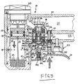
- the driving tool shown partially in section in FIGS. 1 to 5 has a housing 10 and a working cylinder 11 which receives a driving piston 12 to which a driving plunger 13 is connected. At the lower end of the working cylinder 11, a brake ring 14 is arranged.
- the working cylinder 11 is surrounded by a piston return chamber 15 which is connected to the working cylinder 11 via first radial bores 16 and second radial bores 17, the bores 16 on the side of the return chamber 15 being closed by an O-ring 18 which forms a check valve .
- the housing 11 has a handle part 20, in which a reservoir 21 for compressed air is formed, which can be connected to a compressed air source (not shown), for example via a compressed air hose.
- a ventilation channel 22 is formed in the handle part 20.
- a valve plate 23 is attached to the underside of the grip part 20, which engages with a projection 24 in a corresponding recess in the housing 10.
- the valve plate 23 is screwed to the handle 20 by means of a screw 25 which is arranged countersunk in the valve plate 23.
- the valve plate 23 supports a release lever 26 which is pivotably mounted at 27.
- a bore 30 in the grip part 20 is connected to a channel 31, which leads to the working space 32 of the cylinder 11. Above, the working drawer 32 is closed by a cover plug 33.
- a control valve device 36 is received in the bore 30. It has a main valve spool 37 and an auxiliary valve spool 38.
- the main valve spool 37 is designed as a stepped piston with an end-side active surface 37a facing the reservoir 21 and an oppositely directed larger active surface facing a main control chamber 39.
- the piston section of the main valve spool 37 which has the active surface 37a has two axially spaced O-rings 41, 42, the O-ring 41 cooperating with an upper valve seat, as a result of which the connection between the channel 31 and the reservoir 21 is interrupted.
- the lower O-ring 42 interacts with a stepped bush 43 which is sealingly received by the bore 30.
- the bushing bore guides the piston section of the main valve spool 37 in a sliding and sealing manner.
- the channel 31 is connected to an annular space 45 surrounding the main valve spool 37, which is connected to an annular space 46 surrounding the bush 43 via radial bores in the bush 43, which is in constant communication with the Vent channel 22.
- the working displacement 32 is therefore under atmospheric pressure.
- the central bore of the main valve spool 37 slidably and sealingly receives the upper end of a control sleeve 48 which has a radial flange 49 which is seated in an enlarged section of the bore 30.
- the control sleeve 48 has a plurality of radial bores 50 which connect the bore of the control sleeve 48 to the main control chamber 39.
- the radial flange 49 bears against the bush 43 from below and is in turn held by the valve plate 23 from below.
- the bore of the control sleeve 48 receives the upper part of the two-part auxiliary valve spool 38. This consists of an upper smooth cylindrical section 51 with an active surface 52 which faces the reservoir 21 via the bore 47 of the main valve slide 37.
- the upper part of the auxiliary valve slide also has a smooth cylindrical section 53.
- the intermediate rod is triangular in cross section in the central region, as shown at 54.
- a passage is thereby formed between the sections 51 and 53 between the rod 54 and the bore wall of the control sleeve 48 Bore of the control sleeve 48 has in the region of the flange 49 an enlarged section 55 into which the smooth cylindrical section 53 can be inserted in a sealing manner.
- the distance between the smooth cylindrical sections 51, 53 is such that either the upper smooth cylindrical section 51 sits sealingly in the bore of the control sleeve 48, while the section 53 releases the bore section 55, or the smooth cylindrical section 53 sits in the bore section 55, in which case the smooth cylindrical Section 51 projects upwards so far from the control sleeve 48 that the passage around the valve rod 54 is connected to the bore 47 of the main valve spool and thus to the reservoir 21 (FIG. 4).
- the lower part of the auxiliary valve spool 38 is arranged in a bore 56a of the valve plate 23. It has a valve piston section 56 which can be moved in a sealed manner in the bore 56a.
- a piston section 57 with a polygonal cross section - preferably triangular - is seated in a corresponding bore in the valve plate 23.
- the lower part of the auxiliary valve spool 38 has an active surface 57a and a polygonal active surface 66, which together via an oblique bore 58 in the valve plate 23 with the return chamber 15 communicates.
- a plunger 60 of a release valve 61 interacts with the release lever 26. It is pressed by the air pressure in the grip space 21 and in a bore 63a of an insert 63 supported by a spring 62 in the direction of the release lever 26. An O-ring 62a closes the bore in the valve plate 23 downwards.
- the plunger 60 which is triangular in cross-section in the lower region, has a further sealing ring 64 at the upper end, which sealingly cooperates with the bore 63a in the insert 63 when the plunger is lifted upwards using the release lever 26.
- a control chamber 65 is separated from the reservoir 21, which is connected to the bore 56a in the position of the auxiliary valve slide 38 shown in FIG. 1.
- the control valve device described operates as follows.
- Fig. 1 shows the unactuated state again.
- the trigger lever 26 is shown in its unactuated position.
- the pressure in the chamber 65 is the same as in the reservoir 21, since a connection is made via the bore 63a.
- the effective area 40 of the main valve slide 37 is larger than the effective area 37a facing the reservoir 21, the main valve slide is held in the closed position shown in FIG. 1, in which it blocks the connecting channel 31 from the compressed air and via the annular space 45 to the outlet channel 22 connects.
- the piston 12 is in its top dead center position.
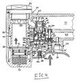
- the main valve spool 37 is held in the closed position even when the upper part of the auxiliary valve spool 38 is in its upper position (which is shown approximately in FIG. 4).
- the cylindrical portion 51 is then outside the bore of the control sleeve 48, so that the passage between the connecting rod 54 and the control sleeve 48 is also connected via the bore 47 of the main valve spool 37 with compressed air, which then also via the radial bores 50 in the Main control chamber 39 can enter.
- valve tappet of the release valve 61 is raised and the sealing ring connected to the valve tappet 64 enters the lower section of the bore 63a of the insert 63, so that the compressed air is shut off.
- the sealing ring 62a emerges from the associated bore of the valve plate 23. Since the valve tappet is polygonal, preferably triangular in cross section in the lower region, a connection of the control chamber 65 to the atmosphere is established.
- the bores 56a, 55 and the radial bores 50 now also connect the main control chamber 39 to the atmosphere.
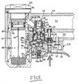
- the pressure acting on the smaller effective surface 37a of the main valve spool 37 therefore moves the main valve spool 37 into the opening position shown in FIG. 3, in which the O-rings 41, 42 interact with the bore of the bush-shaped insert 43 and thereby connect the connecting channel 31 to Shut off outlet duct 22.
- the compressed air enters the working stroke space 32 and drives the driving piston 12 downward so that a driving impact is carried out on a fastening means.
- the driving piston 12 hits the brake ring 14 with its lower end face. Its upper end face exposes the bores 16, and the compressed air can come out of the working space 32 via the bores 16 and the seal acting as a check valve Ring 18 flow into the return chamber 15.
- the return chamber 15 is connected to the bore 56a via the bores 58 and 58a. If this bore is closed (the throttling of bore 58 will be described further below), the control valve device described operates as a single-shot device. As long as the trigger lever 26 is actuated, the driving piston 12 remains in the bottom dead center position. When the release lever 26 is released, the valve pin 60 is pushed down again by the compression spring 62 and the air pressure.
- auxiliary control chamber 65 This separates the auxiliary control chamber 65 from the atmosphere.
- the auxiliary control chamber 65 is pressure-connected to the reservoir 21, so that a pressure can build up again in the main control chamber 39, which adjusts the main valve slide 37 back to the closed position.
- the working stroke space 32 is reconnected to the atmosphere, and the compressed air stored in the return space 15 drives the driving piston 12 back to the top dead center position. A state as shown in FIG. 1 is thereby obtained again.
- the control valve device described operates as an automatic valve. If the compressed air from the return chamber 15 passes through the bore 58 and 58a into the bore 56a, it acts on the lower active surface 57a and on the polygonal lower active surface 66 of the lower part of the auxiliary valve spool 38 and presses it upwards, while at the same time pressing the upper one Takes part and reached the position shown in Fig. 4.
- the plate 23 has a connection bore 102 below the bore 56a, in which the second part of the auxiliary valve spool is arranged, which normally goes into the atmosphere.
- a threaded bore of the release lever 26 sits a screw or threaded sleeve 100, the bore of which receives a cylindrical sealing element 101 made of elastomeric material, which is provided with a conical tip 105 at the upper end.
- the bore 102 remains free. As shown in Fig.
- the trigger lever 26 is raised so that the trigger valve 61 responds by the Sealing ring 64 dips into the corresponding bore 63a, but not so far that the conical tip 105 cooperates sealingly with the bore 102, the driving-in device described above is triggered, but only in single-shot operation, even if the throttle 59 in the connecting channel between the return chamber 15 and the second active surface 57a is open.
- the connection of the second active surface 57a to the atmosphere has the effect that the auxiliary valve slide cannot initiate automatic reversal of the main valve as long as the bore 102 is connected to the atmosphere.
- the operating mode depends on the actuation position of the release lever 26.
- sealing element other than the one shown can also effect a bore 102 seal, for example an annular seal.
- Fig. 6 shows a section through the housing 10 and part of the valve plate 23 in the region of a seal 70, via which the extension 24 is sealed off from the housing 10.
- the bore 58a can be seen, which connects the return chamber 15 to the bore 56a via the bore 58.
- the throttle 59 can be seen, which cooperates with the bore 58. It consists of a screw which has a knurled head 71, a threaded section 72 and a throttle section 73, which is conical at 74 at the end. With the help of the throttle screw, the size of the flow cross-section through the bore 58 can be set as desired. It determines the repetition frequency of the control valve device.
- the control valve device shown has the following advantages. It works without dynamically loaded springs. The only spring provided is the compression spring 62 for the trigger valve. However, it is not dynamically loaded. Furthermore, the control valve device shown is provided with very little dynamically loaded O-rings. In the embodiment shown, only five O-rings dynamically loaded with the stroke frequency are required, a number that is far exceeded by known control valve devices. For example, the upper part of the auxiliary valve spool 38 works completely without O-rings and the lower part has only one O-ring.
- the control valve device described can be used equally for single-shot and repeating operation.
- single-shot operation the lower part of the auxiliary valve slide remains in its lower position shown in FIG. 1.
- the control valve device shown provides an adaptation to the movement of the driving piston 12.
- the main valve spool is not switched to the closed position until the driving piston 12 has actually reached the bottom.
- the entire available driving energy can be used.
- the working stroke space 32 is only pressurized from the reservoir 21 when the driving piston 12 has actually reached its top dead center position.
- the piston sections 56 and 57 of the lower part have a particularly large active surface 57a and 66. It is therefore sufficient to hold the auxiliary valve slide 38 in the upper position, so that a reversal only takes place when the driving piston 12 has actually assumed its top dead center position.
- control valve device described can be installed in conventional nailers which are already in operation. Only the hole 58a has to be made additionally.
Abstract
Description
Die Neuerung bezieht sich auf eine Steuerventileinrichtung an einem mit Druckluft betriebenen Gerät zum Eintreiben von Befestigungsmitteln nach dem Oberbegriff des Anspruchs 1.The innovation relates to a control valve device on a device operated with compressed air for driving in fasteners according to the preamble of claim 1.
Bekannte Geräte dieser Gattung dienen zum Entreiben von Nägeln, Klammern oder dergleichen. Der Eintreibkolben zur Betätigung des Eintreibstößels wird pneumatisch betrieben. Die Auslösung erfolgt mit Hilfe eines Drückers oder eines Auslösehebels, der ein Auslöseventil betätigt. Das Auslöseventil steuert seinerseits ein Steuerventil, das in seiner Öffnungsstellung den Hubraum des Arbeitskolbens mit einer Druckluftquelle verbindet, während es in der geschlossenen Stellung den Arbeitshubraum entlüftet.Known devices of this type are used to rub nails, staples or the like. The driving piston for actuating the driving plunger is operated pneumatically. The release takes place with the help of a pusher or a release lever that actuates a release valve. The trigger valve in turn controls a control valve which, in its open position, connects the displacement of the working piston to a compressed air source while it is in vented the working displacement in the closed position.
Bei derartigen Geräten erfolgt üblicherweise ein einzelner Eintreibschlag, wenn das Auslöseventil von Hand betätigt wird. Der Eintreibkolben gelangt erst wieder in die obere Totpunktstellung, wenn die Auslösung beendet wird. In vielen Fällen ist ein fortlaufendes automatisches Eintreiben von Befestigungsmitteln gewünscht, ohne daß hierfür eine Betätigung pro Eintreibvorgang erforderlich wird. Hierzu bedarf es einer Steuerventileinrichtung, die automatisch das Steuerventil in Schließstellung bringt und damit den Kolbenrückholvorgang einleitet, wenn der Eintreibvorgang beendet ist, um ein neues Arbeitsspiel zu beginnen.In devices of this type, a single driving stroke usually occurs when the trigger valve is actuated by hand. The driving piston does not return to the top dead center position until the triggering is ended. In many cases, continuous automatic driving of fasteners is desired without the need for actuation per driving process. This requires a control valve device which automatically brings the control valve into the closed position and thus initiates the piston return process when the driving-in process has ended in order to start a new work cycle.
Aus der DE-PS 16 03 979 ist eine Steuerventileinrichtung bekanntgeworden, bei der ein Steuerkolben von einer Feder ständig in Schließstellung vorgespannt ist. Gleichachsig zum Steuerkolben ist ein Steuerventilkolben vorgesehen, der bei entsprechender Druckbeaufschlagung den Steuerkolben in die Öffnungsstellung schiebt. Die Druckluftbeaufschlagung des Steuerkolbens wird durch ein Umsteuerventil gesteuert, das eine Wirkfläche des Steuerventils wahlweise mit Atmosphäre oder Druckluft beaufschlagt. Nachteilig bei dem bekannten Gerät ist, daß die Rückholfeder am Steuerkolben ein ausgesprochenes Verschleißteil ist, das nach einer bestimmten Anzahl von Eintreibvorgängen ermüdet. Nachteilig ist ferner, daß der Steuerkolben mit Hilfe des Steuerventilkolbens in die Öffnungsstellung gebracht wird. Dadurch wird der Steuerventilkolben und auch der Steuerkolben mechanisch stark belastet. Außerdem entstehen unangenehme Geräusche. Besonders nachteilig ist jedoch, daß eine Synchronisation der Umsteuerung des Automatikventils mit der Bewegungsfolge des Eintreibkolbens nicht vorhanden ist. Es besteht die Gefahr, daß der Umsteuervorgang bereits eingeleitet wird, bevor der Eintreibkolben seinen vollständigen Schlag ausgeführt hat. Das Befestigungsmittel wird daher unter Umständen nicht mit genügender Energie beaufschlagt und nicht weit genug eingetrieben. Ferner besteht die Gefahr, daß der Arbeitshubraum des Eintreibkolbens bereits mit Druckluft beaufschlagt wird, bevor er seine obere Totpunktstellung erreicht hat. Der Eintreibkolben wird ebenfalls nicht mit ausreichender Energie vorgetrieben. Es kann ferner geschehen, daß der Eintreibkolben überhaupt kein Befestigungsmittel austreibt, da er sich nicht ausreichend weit der oberen Totpunktlage nähert. Der Eintreibstößel verhindert dadurch ein Eintreten eines Befestigungsmittels in den Ausstoßkanal.From DE-PS 16 03 979 a control valve device has become known in which a control piston is constantly biased by a spring in the closed position. A control valve piston is provided coaxially with the control piston and pushes the control piston into the open position when the pressure is applied accordingly. The pressurized air supply to the control piston is controlled by a reversing valve, which optionally applies an atmosphere or compressed air to an active surface of the control valve. A disadvantage of The known device is that the return spring on the control piston is a pronounced wearing part that tires after a certain number of driving operations. Another disadvantage is that the control piston is brought into the open position with the aid of the control valve piston. As a result, the control valve piston and the control piston are subjected to high mechanical loads. There are also unpleasant noises. However, it is particularly disadvantageous that there is no synchronization of the reversing of the automatic valve with the sequence of movements of the driving piston. There is a risk that the reversal process is initiated before the driving piston has completed its stroke. The fastener may therefore not be subjected to sufficient energy and may not be driven far enough. There is also the danger that the working piston space of the driving piston is already pressurized with compressed air before it has reached its top dead center position. The driving piston is also not driven with sufficient energy. It can also happen that the driving piston does not drive out any fastening means at all, since it does not approach the top dead center position sufficiently far. The driving plunger thereby prevents a fastener from entering the ejection channel.
Es ist auch eine Steuerventileinrichtung aus der DE-PS 1 603 839 bekanntgeworden, bei der der einem Hauptsteuerventilschieber zugekehrte Steuerraum über ein auf Druck ansprechendes zusätzliches Ventil mit der Kolbenrückholkammer verbunden ist, wobei diese Verbindung durch einen Hilfsventilschieber gesteuert ist. Die Kolbenrückholkammer dient bekanntlich dazu, den Kolben aus der unteren Totpunktstellung wieder in die obere Totpunktstellung zu verstellen, indem sie mit Druckluft gefüllt wird, wenn der Eintreibkolben annähernd seine untere Totpunktstellung erreicht hat. Die Rückholkammer ist mit einer Bohrung unterhalb des Kolbens in der unteren Totpunktlage mit dem Zylinder verbunden, so daß die in der Rückholkammer gespeicherte Luft nunmehr den Rückhub bewerkstelligen kann. Bei der bekannten Steuerventileinrichtung wird nun ein Teil der Druckluft aus der Kolbenrückholkammer abgezweigt, um den Hauptventilschieber wieder in die Schließstellung zu verstellen. Die Druckverhältnisse in der Kolbenrückholkammer sind jedoch von verschiedenen Faktoren abhängig, wie beispielsweise der Reibung des Arbeitskolbens,der Dichtungen usw., so daß nicht immer reproduzierbare Drücke erreicht werden. Das zusätzliche Ventil öffnet daher nicht reproduzierbar bei einer bestimmten Stellung des Arbeitskolbens. Es ist daher auch bei dieser Ventileinrichtung keine exakte Synchronisierung zwischen der Bewegung des Eintreibkolbens und den Schaltvorgängen der Steuerventileinrichtung vorhanden. Die Verstellung des Hauptventilschiebers in die Schließstellung erfordert einen gewissen Druck und ein bestimmtes Volumen, die unter Umständen dann für die Kolbenrückholung nicht zur Verfügung stehen.Außerdem besteht bei dem bekannten Ventil die Gefahr, daß der Umsteuervorgang zu rasch erfolgt und der Eintreibkolben nicht seine obere Totpunktstellung erreicht hat, bevor der Arbeitshubraum erneut mit der Druckluftquelle verbunden wird. Schließlich erfordert das bekannte Ventil eine große Anzahl von dynamisch beanspruchten Dichtungsringen sowie auch eine Rückholfeder im zusätzlichen Ventil. Dichtungsringe und Federn sind jedoch Verschleißteile, die von Zeit zu Zeit ausgewechselt werden müssen.A control valve device has also become known from DE-PS 1 603 839, in which the control chamber facing a main control valve slide is connected to the piston return chamber via an additional pressure-sensitive valve, this connection being controlled by an auxiliary valve slide. As is known, the piston return chamber serves to move the piston from the bottom dead center position back to the top dead center position by filling it with compressed air when the driving piston has approximately reached its bottom dead center position. The return chamber is connected to a bore below the piston in the bottom dead center position with the cylinder, so that the air stored in the return chamber can now accomplish the return stroke. In the known control valve device, part of the compressed air is now branched off from the piston return chamber in order to move the main valve slide back into the closed position. However, the pressure conditions in the piston return chamber are dependent on various factors, such as the friction of the working piston, the seals, etc., so that reproducible pressures are not always achieved. The additional valve therefore does not open reproducibly at a certain position of the working piston. It is therefore also with this valve device there is no exact synchronization between the movement of the driving piston and the switching operations of the control valve device. Moving the main valve spool to the closed position requires a certain pressure and a certain volume, which may not be available for piston return. There is also a risk with the known valve that the reversing process takes place too quickly and the driving piston does not reach its top dead center position reached before the working displacement is reconnected to the compressed air source. Finally, the known valve requires a large number of dynamically stressed sealing rings as well as a return spring in the additional valve. However, sealing rings and springs are wear parts that need to be replaced from time to time.
Die gleichen Schwierigkeiten wie bei der oben beschriebenen Ventilanordnung ergeben sich bei der bekannten Ventilanordnung nach der DE-PS 3 222 949, bei der der Rückholraum des Eintreibgerätes unmittelbar mit einer Wirkfläche des Hauptventils verbunden wird, das als sogenanntes Kopfventil koaxial zum Eintreibkolben oberhalb des Arbeitszylinders angeordnet ist. Eine derartige Ventilanordnung ist zwar mechanisch einfach aufgebaut, weil sie ohne Hilfsven til arbeitet, sie weist jedoch eine schlechte Regelbarkeit der Repetierfrequenz auf. Ferner ist zwischen der Rückholkammer und der entsprechenden Wirkungsfläche des Hauptventils ein verhältnismäßig langer Luftweg angeordnet, der für eine schnelle Umsteuerung nachteilig ist. Mit dem bekannten Ventil lassen sich daher nur relativ geringe Repetierfrequenzen erreichen. Schließlich erfolgt eine Umsteuerung nur, wenn nahezu voller Druckaufbau stattgefunden hat, da die Differenzflächen sehr klein sind.The same difficulties as with the valve arrangement described above arise in the known valve arrangement according to DE-PS 3 222 949, in which the return space of the driving device is connected directly to an active surface of the main valve, which is arranged as a so-called head valve coaxially to the driving piston above the working cylinder is. Such a valve arrangement is mechanically simple because it has no auxiliary veins til works, but it has poor controllability of the repetition frequency. Furthermore, a relatively long air path is arranged between the return chamber and the corresponding effective area of the main valve, which is disadvantageous for rapid reversal. With the known valve, therefore, only relatively low repetition frequencies can be achieved. Finally, a reversal only takes place when the pressure has increased almost completely, since the difference areas are very small.
Aus der US-PS 3 808 620 ist ein aufwendiger aufgebautes Ventil bekanntgeworden, dessen Hauptventil ebenfalls als Kopfventil ausgebildet ist. Der Hilfsventilschieber ist in einer Hülse verschiebbar angeordnet, die ihrerseits verschiebbar im Gehäuse des Eintreibgeräts gelagert ist. Im Einzelschußbetrieb bleibt die Hülse in einer vorgegebenen Endposition. Bei Repetierbetrieb wird die Hülse von dem Druck im Kolbenrückholraum beaufschlagt und relativ zum Hilfsventilschieber verstellt. Dadurch wird dieser wieder in die Ursprungslage zurückgebracht und das Hauptventil wird auf diese Weise umgesteuert. Diese bekannte Ventilanordnung weist ebenfalls einige Nachteile auf. Die im Repetierbetrieb oszillierende Hülse ist verhältnismäßig groß ausgeführt und besitzt daher eine relativ große Masse, was für hohe Repetierfrequenzen ungünstig ist. Die oszillierende Hülse ist ebenso wie der Hilfsventilschieber mit einer großen Reihe von dynamisch belasteten O-Ringen versehen, die einem relativ starken Verschleiß ausgesetzt sind. Außerdem ist bei O-Ringen eine höhere Umsteuerkraft erforderlich. Bei der bekannten Ventilanordnung sind außerdem die Differenzflächen relativ klein. Eine Umsteuerung erfolgt daher nur nach nahezu vollständigem Druckaufbau bzw. -abbau. Bei höheren Repetierfrequenzen besteht daher die Gefahr, daß der Arbeitskolben bereits mit Druckluft beaufschlagt wird, während er noch im Rückhub begriffen ist.From US-PS 3 808 620 a complex valve has become known, the main valve is also designed as a head valve. The auxiliary valve slide is slidably arranged in a sleeve, which in turn is slidably mounted in the housing of the driving tool. In single-shot mode, the sleeve remains in a predetermined end position. In repeating operation, the sleeve is acted upon by the pressure in the piston return space and adjusted relative to the auxiliary valve spool. This brings it back to its original position and the main valve is reversed in this way. This known valve arrangement also has some disadvantages. The sleeve, which oscillates in repetition mode, is relatively large and therefore has a relatively large mass, which is unfavorable for high repetition frequencies. Like the auxiliary valve spool, the oscillating sleeve is provided with a large number of dynamically loaded O-rings that are subject to relatively heavy wear. In addition, a higher reversing force is required for O-rings. In the known valve arrangement, the difference areas are also relatively small. A reversal therefore only takes place after almost complete pressure build-up or reduction. At higher repetition frequencies there is therefore a risk that the working piston is already pressurized with compressed air while it is still in the return stroke.
Eine Steuerventileinrichtung der eingangs genannten Art ist aus der DE-PS 19 08 150 bekanntgeworden. Ein Hilfsventilschieber ist ebenfalls stufenkolbenförmig ausgebildet, der mit einer Kolbenstufe einen eigenen Steuerraum begrenzt, der über eine vom Hauptventilschieber steuerbare Leitung in der geöffneten Ventilstellung mit der Druckleitung und in der geschlossenen Ventilstellung mit einer Entlüftungsleitung verbindbar ist. Der Hilfsventilschieber steuert seinerseits die Druckbeaufschlagung des Hauptventilschiebers. Die Umsteuerung des Hauptventilschiebers beginnt erst, wenn der Hauptventilschieber vollständig in die Öffnungsstellung gelangt ist, so daß sich im Arbeitshubraum ein ausreichender Druck aufbauen kann, um den Eintreibkolben anzutreiben. Ein erneutes Arbeitsspiel wird erst eingeleitet, wenn aus dem Arbeitszylinder während des Kolbenrückhubs fast keine Luft mehr ausströmt. Bei der bekannten Ventileinrichtung wird die ausströmende Luft über eine steuerbare Leitung in den weiteren Steuerraum eingeleitet, so daß dessen Entlüftung erst eintreten kann, wenn die entgegenströmende Luft aus dem Arbeitshubraum nahezu oder vollständig entwichen ist. Mit Hilfe dieser Maßnahmen soll eine Anpassung an den Bewegungsablauf des Eintreibkolbens erzielt werden in der Weise, daß der Eintreibkolben stets einen vollen Arbeits- und einen vollen Rückhub ausführt. Es hat sich jedoch gezeigt, daß vor allen Dingen bei höheren Eintreibfrequenzen die beabsichtigte Synchronisation nicht mehr erreicht wird. Die Zeit, die zwischen den Umsteuervorgängen verstreicht, ist im wesentlichen durch die Verbindungskanäle, die ggf. Drosselstellen aufweisen können, vorgegeben. Sind die Strömungsquerschnitte zu klein oder zu groß, kann es daher geschehen, daß der Eintreibkolben vor dem unteren Totpunkt bereits druckentlastet wird oder vor dem oberen Totpunkt bereits wieder mit Druck beaufschlagt wird. Nachteilig bei der bekannten Steuerventileinrichtung ist ferner, daß eine große Anzahl von dynamischen Dichtringen erforderlich ist, die bekanntlich als Verschleißteile zu betrachten sind.A control valve device of the type mentioned has become known from DE-PS 19 08 150. An auxiliary valve spool is also designed in the form of a stepped piston, which delimits its own control space with a piston step, which can be connected to the pressure line in the open valve position and to a vent line in the closed valve position via a line controllable by the main valve spool. The auxiliary valve spool in turn controls the pressurization of the main valve spool. The reversing of the main valve spool only begins when the main valve spool is completely in the open position has reached so that sufficient pressure can build up in the working stroke space to drive the driving piston. Another working cycle is only initiated when almost no air flows out of the working cylinder during the piston return stroke. In the known valve device, the outflowing air is introduced into the further control chamber via a controllable line, so that its ventilation can only occur when the countercurrent air has almost or completely escaped from the working stroke space. With the aid of these measures, an adaptation to the movement sequence of the driving piston is to be achieved in such a way that the driving piston always executes a full working and a full return stroke. However, it has been shown that, above all, the intended synchronization is no longer achieved at higher drive frequencies. The time that elapses between the reversal processes is essentially predetermined by the connecting channels, which may have throttling points. If the flow cross-sections are too small or too large, it can therefore happen that the driving piston is already relieved of pressure before bottom dead center or that pressure is already applied again before top dead center. Another disadvantage of the known control valve device is that a large number of dynamic sealing rings is required, which are known to be regarded as wearing parts.
Der Neuerung liegt daher die Aufgabe zugrunde, eine Steuerventileinrichtung an einem mit Druckluft betriebenen Gerät zum Eintreiben von Befestigungsmitteln zu schaffen, das ein Minimum an Verschleißteilen aufweist und vor allen Dingen eine exakte Anpassung der Umschaltvorgänge an die Bewegung des Eintreibkolbens auch bei hohen Eintreibfrequenzen im sogenannten Repetierbetrieb gewährleistet.The innovation is therefore based on the task of creating a control valve device on a device operated with compressed air for driving in fasteners, which has a minimum of wearing parts and, above all, an exact adaptation of the switching processes to the movement of the driving piston even at high driving frequencies in the so-called repeating mode guaranteed.
Diese Aufgabe wird durch die Merkmale des Kennzeichnungsteils des Anspruchs 1 gelöst.This object is achieved by the features of the characterizing part of claim 1.
Die neuerungsgemäße Steuerventileinrichtung kommt wie die gattungsgemäße Ventileinrichtung ohne dynamisch belastete Federn aus. Für das Auslöseventil bzw. dessen Schaft kann eine Druckfeder vorgesehen sein, die jedoch nicht dynamisch belastet wird. Die neuerungsgemäße Steuerventileinrichtung kommt ferner mit einer sehr geringen Anzahl von dynamisch belasteten Dichtringen aus, so daß sie eine minimale Verschleißanfälligkeit aufweist und größere Wartungsabstände erlaubt.The new control valve device, like the generic valve device, does not require any dynamically loaded springs. A compression spring can be provided for the release valve or its stem, but is not dynamically loaded. The new control valve device also comes with a very small number of dynamically loaded sealing rings, so that it has minimal susceptibility to wear and allows longer maintenance intervals.
Wie ferner bei der gattungsgemäßen Steuerventileinrichtung kommt die neuerungsgemäße Einrichtung mit lediglich zwei Ventilschiebern aus, wobei der Hauptventilschieber den Kanal zum Arbeitschubraum steuert, während der Hilfsventilschieber die Druckbeaufschlagung der größeren Wirkfläche des Hauptventilschiebers steuert. Neuerungswesentlich ist nun, daß die zweite Wirkfläche des Hilfsventilschiebers unmittelbar mit dem Kolbenrückholraum in Verbindung steht. Diese Verbindung, die von einer einfachen Querbohrung gebildet sein kann, enthält vorzugsweise eine Drossel, etwa in Form einer Stellschraube oder einer Nadel zur Verstellung des Strömungsquerschnitts. Wird die Bohrung vollständig geschlossen, arbeitet das neuerungsgemäße Gerät im Einzelschußbetrieb. Der von der Drossel eingestellte Durchströmquerschnitt in der Bohrung bestimmt hingegen die Repetierfrequenz des automatisch arbeitenden Steuerventils.As is also the case with the control valve device of the generic type, the device according to the innovation manages with only two valve spools, the main valve spool controlling the channel to the working push chamber, while the auxiliary valve spool controls the pressurization of the larger effective area of the main valve spool. It is now essential for the innovation that the second active surface of the auxiliary valve slide is directly connected to the piston return space. This connection, which can be formed by a simple transverse bore, preferably contains a throttle, for example in the form of an adjusting screw or a needle for adjusting the flow cross section. If the hole is completely closed, the new device works in single-shot mode. The flow cross-section in the bore set by the throttle, however, determines the repetition frequency of the automatically operating control valve.
Das Auslöseventil sorgt im entspannten bzw. nicht betätigten Zustand dafür, daß die größere Wirkfläche des Hauptventilschiebers mit dem Druck der Druckluftquelle, beispielsweise dem Reservoir im Griff des Eintreibgerätes, beaufschlagt wird. Dadurch bleibt der Hauptventilschieber ständig in der geschlossenen Stellung und sperrt die Verbindung der Druckluftquelle mit dem Arbeitschubraum. Durch Betätigung des Auslöseventils wird jedoch die größere Wirkfläche des Hauptventilschiebers entlüftet. Der Hilfsventilschieber kann dabei seine Position beibehalten. Beispielsweise kann ein durch Betätigung des Auslöseventils mit Atmosphäre verbundener Raum in der Ausgangsstellung des Hilfsventilschiebers ständig über eine Verbindung mit der größeren Wirkfläche des Hauptventilschiebers verbunden sein. Der Druck auf die kleinere Wirkfläche des Hauptventilschiebers führt daher zu einer Verstellung in seine Öffnungsstellung, in der er den Verbindungskanal zwischen Druckluftquelle und Arbeitschubraum freigibt. Der Eintreibkolben wird nach unten getrieben und treibt das Befestigungsmittel in ein Werkstück. Hat der Eintreibkolben seine untere Position (unterer Totpunkt) erreicht, kann über eine Bohrung im Zylinder die Druckluft in einen den Zylinder umgebenden Rückholraum strömen. Aus dem Rückholraum strömt etwas Luft über die beschriebene Bohrung und die darin angeordnete Drossel zur zweiten Wirkfläche des Hilfsventilschiebers. Dieser wird daraufhin in seine zweite Stellung verstellt, in der er nunmehr die größere Wirkfläche des Hauptventilschiebers mit der Druckluftquelle verbindet. Der Hauptventilschieber wird daraufhin wieder in die Schließstellung verstellt, trennt daher die Verbindung zwischen Druckluftquelle und Arbeitschubraum und legt statt dessen den Arbeitschubraum an Atmosphäre. Die im Rückholraum gespeicherte Luft drückt nunmehr den Kolben in Richtung obere Totpunktstellung. Während der gesamten Rückholzeit ist die Rückholkammer bis zuletzt unter einem gewissen Druck, so daß die zweite Wirkfläche des Hilfsventilschiebers mit diesem Druck beaufschlagt wird und die Rückkehr des Hilfsventilschiebers in die Anfangsstellung verhindert. Bei Vorzeichenumkehr der Druckdifferenz fließt dann die Luft unter Druck von der zweiten Wirkfläche des Hilfsventilschiebers zum Rückholraum und unterstützt dabei dessen Rückholwirkung. Wird die zweite Wirkfläche des Hilfsventilschiebers entsprechend groß ausgelegt, kann ohne weiteres erreicht werden, daß der Hilfsventilschieber erst dann in seine erste oder Anfangsstellung zurückkehrt, wenn der Eintreibkolben mit Sicherheit seine obere Totpunktlage erreicht hat. Irgendwann wird der Hilfventilschieber durch den Druck der Druckluftquelle in die Anfangsstellung zurückverstellt, so daß er erneut die größere Wirkfläche des Hauptventilschiebers mit Atmosphäre verbindet, und ein neues Arbeitsspiel beginnen kann.The release valve ensures, in the relaxed or non-actuated state, that the larger effective area of the main valve spool is acted upon by the pressure of the compressed air source, for example the reservoir in the handle of the driving tool. As a result, the main valve spool remains in the closed position and blocks the connection of the compressed air source to the working drawer. By Actuation of the trigger valve, however, the larger effective area of the main valve spool is vented. The auxiliary valve slide can keep its position. For example, a space connected to the atmosphere by actuation of the trigger valve in the starting position of the auxiliary valve spool can be permanently connected via a connection to the larger effective area of the main valve spool. The pressure on the smaller effective area of the main valve slide therefore leads to an adjustment to its open position, in which it releases the connecting channel between the compressed air source and the working push chamber. The driving piston is driven down and drives the fastener into a workpiece. When the driving piston has reached its lower position (bottom dead center), the compressed air can flow into a return space surrounding the cylinder via a hole in the cylinder. Some air flows out of the return space via the described bore and the throttle arranged therein to the second active surface of the auxiliary valve spool. This is then adjusted to its second position, in which it now connects the larger effective area of the main valve spool with the compressed air source. The main valve spool is then moved back to the closed position, therefore separates the connection between the compressed air source and the working drawer and sets instead, the working push room in atmosphere. The air stored in the return space now pushes the piston towards the top dead center position. During the entire return time, the return chamber is under a certain pressure until the end, so that this pressure is applied to the second active surface of the auxiliary valve spool and prevents the auxiliary valve spool from returning to the initial position. When the sign of the pressure difference is reversed, the air flows under pressure from the second active surface of the auxiliary valve spool to the return space and thereby supports its return effect. If the second effective area of the auxiliary valve spool is designed to be large, it can easily be achieved that the auxiliary valve spool only returns to its first or initial position when the driving piston has reached its top dead center position with certainty. At some point the auxiliary valve spool is returned to the initial position by the pressure of the compressed air source, so that it connects the larger effective area of the main valve spool with atmosphere again and a new work cycle can begin.
Wie erkennbar, kann beim erfindungsgemäßen Automatikventil eine Umschaltung erst dann vorgenommen werden, wenn der Eintreibkolben tatsächlich seine untere Totpunktstellung erreicht hat. Umgekehrt wird der Arbeitshubraum des Eintreibkolbens mit der Druckquelle erst dann verbunden, wenn er seine obere Totpunktlage erreicht hat. Beim neuerungsgemäßen Steuerventil wird daher die maximal zur Verfügung stehende Energie ausgenutzt, um Befestigungsmittel wirksam einzutreiben, auch und vor allen Dingen im Repetierbetrieb.As can be seen, the automatic valve according to the invention can only be switched over when the driving piston actually has its bottom dead center position has reached. Conversely, the working stroke of the driving piston is only connected to the pressure source when it has reached its top dead center position. In the control valve according to the innovation, the maximum available energy is therefore used to drive in fasteners effectively, and above all in repeating operation.
Ähnlich wie bei der eingangs beschriebenen Steuerventileinrichtung weist das neuerungsgemäße Ventil eine feststehende Steuerhülse aus, die dichtend mit einer mittigen Durchbohrung des Hauptventilschiebers zusammenwirkt. Die Steuerhülse kann neuerungsgemäß einen radialen Flansch aufweisen, durch den der Hauptsteuerraum, dem die größere Wirkfläche des Hauptventilschiebers zugekehrt ist, begrenzt. Der Hilfsventilschieber ist neuerungsgemäß in der Bohrung der Steuerhülse verschiebbar geführt.Similar to the control valve device described at the outset, the valve according to the innovation has a fixed control sleeve, which cooperates in a sealing manner with a central bore in the main valve spool. According to the innovation, the control sleeve can have a radial flange through which the main control space, to which the larger effective area of the main valve spool faces, delimits. According to the innovation, the auxiliary valve slide is displaceably guided in the bore of the control sleeve.
Die zweite Wirkfläche des Hilfsventilschiebers, die wahlweise dem Druck des Kolbenrückholraums ausgesetzt ist, wird vorzugsweise vehältnismäßig viel größer ausgebildet als die erste Wirkfläche. Wird der Hilfsventilschieber außerdem mit einer Wirkfläche versehen, die ständig dem Druck der Druckluftquelle ausgesetzt ist, wird die zweite Wirkfläche so groß gewählt, daß sie mindestens doppelt so groß ist wie die dem Druck der Druckluftquelle ständig ausge setzte Wirkfläche. Auf diese Weise ist sichergestellt, daß während des Rückhubs des Kolbens der Hilfsventilschieber in einer Stellung verbleibt, in der der Steuerraum des Hauptventilschiebers mit der Druckluftquelle verbunden ist. Erst wenn der Druck im Kolbenrückholraum nahezu vollständig abgebaut ist auf einen Bruchteil des Maximaldrucks, gelangt der Hilfsventilschieber wieder in seine erste Stellung und leitet damit das Öffnen des Hauptventils ein, so daß der Arbeitskolben zur Ausführung eines neuen Arbeitshubs mit Druck beaufschlagt werden kann. Auf diese Weise ist sichergestellt, daß der Kolben seine obere Totpunktlage erreicht hat, bevor ein neuer Arbeitshub ausgeführt wird.The second effective area of the auxiliary valve slide, which is optionally exposed to the pressure of the piston return space, is preferably designed to be much larger than the first effective area. If the auxiliary valve slide is also provided with an effective area that is constantly exposed to the pressure of the compressed air source, the second effective area is selected to be large enough that it is at least twice as large as the pressure of the compressed air source set effective area. In this way it is ensured that during the return stroke of the piston the auxiliary valve spool remains in a position in which the control chamber of the main valve spool is connected to the compressed air source. Only when the pressure in the piston return space is almost completely reduced to a fraction of the maximum pressure, does the auxiliary valve slide return to its first position and thus initiates the opening of the main valve, so that the working piston can be pressurized to carry out a new working stroke. In this way it is ensured that the piston has reached its top dead center position before a new working stroke is carried out.
Die erste Wirkfläche des Hilfsventilschiebers ist vorzugsweise von einem Kolbenabschnitt gebildet. Ein weiterer Kolbenabschnitt des Hilfsventilschiebers ist dichtend in der Bohrung der Steuerhülse angeordnet. Die beschriebenen Kolbenabschnitte sind jedoch derart, daß immer nur einer der beiden mit der Bohrung der Steuerhülse dichtend zusammenwirkt. Die Kolbenabschnitte sind glattzylindrisch ohne Dichtelemente ausgebildet, so daß verschleißanfällige Dichtungen beim Hilfsventilschieber weitgehend entfallen. Lediglich der Kolbenabschnitt, der die zweite Wirkfläche bildet, ist in der zugeordneten Gehäusebohrung vorzugsweise über einen O-Ring abgedichtet. Der Hilfsventilschieber ist daher äußerst leichtgängig, was für die Erreichung hoher Repetierfrequenzen bis zu 2000 pro Minute von verheblichem Vorteil ist.The first active surface of the auxiliary valve slide is preferably formed by a piston section. Another piston section of the auxiliary valve spool is sealingly arranged in the bore of the control sleeve. However, the piston sections described are such that only one of the two cooperates in a sealing manner with the bore of the control sleeve. The piston sections are of smooth cylindrical design without sealing elements, so that seals susceptible to wear are largely eliminated in the auxiliary valve slide. Only the piston section, which forms the second active surface, is preferred in the associated housing bore sealed with an O-ring. The auxiliary valve spool is therefore extremely smooth-moving, which is of considerable advantage for achieving high repetition frequencies of up to 2000 per minute.
Der Hilfsventilschieber kann nach einer weiteren Ausgestaltung der Neuerung aus zwei Teilen bestehen, von denen das eine die mit der Steuerhülse zusammenwirkenden zylindrischen Abschnitte und das andere die zweite Wirkfläche aufweist. Diese Unterteilung ist vorteilhaft, da das untere Teil zum oberen Teil nicht exakt koaxial angeordnet sein muß und somit unterschiedliche, zueinander versetzte Positionen der Ventilbohrungen im Gehäuse und in der Ventilabdeckung realisiert werden können. D.h., daß für die Fertigung die Positionstoleranzen relativ grob sein dürfen.According to a further embodiment of the innovation, the auxiliary valve slide can consist of two parts, one of which has the cylindrical sections interacting with the control sleeve and the other has the second active surface. This subdivision is advantageous since the lower part does not have to be arranged exactly coaxially with the upper part and thus different, offset positions of the valve bores in the housing and in the valve cover can be realized. This means that the position tolerances for production can be relatively rough.
Bei der beschriebenen Ventilanordnung kann durch Veränderung der Drossel zwischen Kolbenrückholkammer und dem Hilfsventilschieber die Frequenz im Automatikbetrieb stufenlos verstellt werden, bis schließlich nur noch Einzelschüsse abgegeben werden. In der Praxis, zum Beispiel in Polstereien, kommt es jedoch häufig vor, daß ein sogenannter Mischbetrieb gefordert wird, d.h. zuerst werden einige Klammern im Einzelschußbetrieb gezielt zum Fixieren des Stoffes eingetrieben. Anschließend wird mit hoher Schußfolge im Automatikbetrieb weitergearbeitet. Für die Umstellung vom Einzelschuß- zum Automatikbetrieb ist zum Beispiel eine Schraube um etwa drei bis vier Umdrehungen zu betätigen. Dies dauert unter Umständen zu lange. Daher sieht eine Ausgestaltung der Erfindung vor, daß zur zweiten Wirkfläche eine zum Auslöser des Auslöseventils gerichtete Bohrung vorgesehen ist, die in der unbetätigten Stellung des Auslösers mit Atmosphäre verbunden ist. Ein Abschnitt des Auslösers trägt ein Dichtelement, das bei Betätigung des Auslösers die Bohrung dichtend verschließt. Die Beziehung des Auslöseventils zu dem Auslöser ist derart, daß ab einer ersten Wegstrecke des Auslösers zwar das Auslöseventil aktiviert wird, um einen Schuß auszulösen, die Bohrung unterhalb der zweiten Wirkfläche jedoch noch offen bleibt. Trotz Automatikstellung der Drossel im Kanal zur zweiten Wirkfläche wird der Automatikbetrieb unterdrückt, und ein neuer Einzelschuß kann erst dann ausgelöst werden, wenn der Auslöser losgelassen und erneut betätigt wird. Wird hingegen der Auslöser eine der ersten Wegstrecke folgenden zweite Wegstrecke verstellt, verschließt das Dichtelement die Bohrung, und das Eintreibgerät arbeitet im Automatikbetrieb. Die beschriebene Anordnung wird vorzugsweise so gewählt, daß die Bedienungsperson bei der Betätigung des Auslösers, beispielsweise eines Auslösehebels, zwei Druckpunkte verspürt, wobei der erste relativ leicht überwunden werden kann, während beim zweiten ein mehr oder weniger deutlicher Anschlag zu spüren ist.In the valve arrangement described, the frequency can be continuously adjusted in automatic mode by changing the throttle between the piston return chamber and the auxiliary valve slide until finally only individual shots are fired. In practice, for example in upholstery, it is often the case that a so-called mixed operation is required, ie first some clips are specifically used for fixing in single-shot operation of the substance. Then the work continues in automatic mode with a high firing order. To switch from single-shot to automatic mode, for example, a screw has to be actuated by about three to four turns. This may take too long. Therefore, an embodiment of the invention provides that a bore directed toward the trigger of the trigger valve is provided for the second active surface and is connected to the atmosphere when the trigger is not actuated. A section of the trigger carries a sealing element which seals the bore when the trigger is actuated. The relationship of the trigger valve to the trigger is such that although the trigger valve is activated from a first distance of the trigger to trigger a shot, the bore below the second active surface remains open. Despite the automatic setting of the throttle in the channel to the second active surface, the automatic mode is suppressed, and a new single shot can only be triggered when the trigger is released and actuated again. If, on the other hand, the trigger is adjusted a second distance following the first distance, the sealing element closes the hole and the driving tool works in automatic mode. The arrangement described is preferably chosen so that the operator at the Actuation of the trigger, for example a trigger lever, feels two pressure points, the first being relatively easy to overcome, while the second one can feel a more or less clear stop.
Zusammenfassend kann festgestellt werden, daß das neuerungsgemäße Ventil mit einer Mindestanzahl von beweglichen Teilen auskommt oder eine exakte Anpassung an den Bewegungsablauf des Eintreibkolbens gewährleistet. Auch bei höchsten Repetierfrequenzen tritt kein Verlust der Schlagenergie dadurch auf, daß noch während der Auf- und Abwärtsbewegung das Ventil umschaltet, vielmehr wird die Kolbenrückholung erst dann eingeleitet, wenn der Schlag ausgeführt wurde. Zum nächsten Schlag wird erst dann umgeschaltet, wenn der Kolben seine obere Totpunktlage erreicht hat. Das erfindungsgemäße Ventil arbeitet auch mit einem Minimum an Verschleißteilen bzw. nur solchen Teilen, die eine sehr hohe Standzeit aufweisen, um auch bei höchsten Repetierfrequenzen über einen längeren Zeitraum keinen Ausfall zu bewirken. Insbesondere sind belastete Federn und dynamisch hochbelastete Dichtelemente (O-Ringe) eliminiert. Das erfindungsgemäße Ventil ist in einem sehr weiten Regelbereich vom Einzelschuß bis zur Höchstgrenze von zum Beispiel 30 Hz stufenlos regelbar. Darüber hinaus ist das neuerungsgemäße Ventil konstruktiv so ausgebildet, daß es in vorhandene Gehäuse von Eintreibgeräten eingebaut werden kann, ohne daß besondere Anpassungsmaßnahmen vorzusehen sind.In summary, it can be stated that the valve according to the innovation manages with a minimum number of moving parts or ensures an exact adaptation to the movement sequence of the driving piston. Even at the highest repetition frequencies, there is no loss of impact energy due to the fact that the valve switches over during the up and down movement. Rather, the piston return is only initiated when the impact has been carried out. The next stroke is only switched over when the piston has reached its top dead center position. The valve according to the invention also works with a minimum of wear parts or only those parts which have a very long service life, so as not to cause a failure over a longer period even at the highest repetition frequencies. In particular, loaded springs and dynamically highly loaded sealing elements (O-rings) are eliminated. The valve according to the invention is infinitely variable in a very wide control range from single shot to a maximum limit of 30 Hz, for example. In addition, the innovation is The design of the valve is such that it can be installed in the existing housing of driving tools without special adaptation measures having to be provided.
Die Neuerung wird nachfolgend anhand von Zeichnungen näher erläutert.
- Fig. 1 zeigt einen Schnitt durch eine Steuerventileinrichtung nach der Neuerung im unbetätigten Zustand.
- Fig. 2 zeigt die gleiche Darstellung wie Fig. 1, jedoch in der Betätigung für Einzelschußbetrieb.
- Fig. 3 zeigt eine gleiche Darstellung wie Fig. 1, jedoch nach einer ersten Betätigungsphase.
- Fig. 4 zeigt eine ähnliche Darstellung wie Fig. 1, jedoch nach einer zweiten Betätigungsphase.
- Fig. 5 zeigt eine ähnliche Darstellung wie Fig. 1, jedoch nach einer dritten Betätigungsphase.
- Fig. 6 zeigt vergrößert einen Schnitt durch die Darstellung nach Fig. 1 entlang der Linie 5-5.
- Fig. 1 shows a section through a control valve device according to the innovation in the unactuated state.
- Fig. 2 shows the same representation as Fig. 1, but in the actuation for single-shot operation.
- Fig. 3 shows the same representation as Fig. 1, but after a first actuation phase.
- FIG. 4 shows a representation similar to FIG. 1, but after a second actuation phase.
- FIG. 5 shows a representation similar to FIG. 1, but after a third actuation phase.
- FIG. 6 shows an enlarged section through the representation according to FIG. 1 along the line 5-5.
Das in den Figuren 1 bis 5 teilweise im Schnitt dargestellte Eintreibgerät weist ein Gehäuse 10 und einen Arbeitszylinder 11 auf, der einen Eintreibkolben 12 aufnimmt, mit dem ein Eintreibstößel 13 verbunden ist. Am unteren Ende des Arbeitszylinders 11 ist ein Bremsring 14 angeordnet. Der Arbeitszylinder 11 wird von einer Kolbenrückholkammer 15 umgeben, die über erste radiale Bohrungen 16 und zweite radiale Bohrungen 17 mit dem Arbeitszylinder 11 verbunden ist, wobei die Bohrungen 16 auf seiten der Rückholkammer 15 durch einen O-Ring 18 verschlossen sind, der ein Rückschlagventil bildet.The driving tool shown partially in section in FIGS. 1 to 5 has a
Das Gehäuse 11 besitzt einen Griffteil 20, in dem ein Reservoir 21 für Druckluft ausgebildet ist, das beispielsweise über einen Druckluftschlauch mit einer Druckluftquelle verbindbar ist (nicht gezeigt). Außerdem ist im Griffteil 20 ein Entlüftungskanal 22 ausgebildet. Am zylinderseitigen Ende ist an der Unterseite des Griffteils 20 eine Ventilplatte 23 angebracht, die mit einem Vorsprung 24 in eine entsprechende Ausnehmung des Gehäuses 10 eingreift. Die Ventilplatte 23 ist mittels einer Schraube 25, die versenkt in der Ventilplatte 23 angeordnet ist, mit dem Griff 20 verschraubt. An der Unterseite lagert die Ventilplatte 23 einen Auslösehebel 26, der bei 27 schwenkbar gelagert ist.The
Eine Bohrung 30 im Griffteil 20 steht in Verbindung mit einem Kanal 31, der zum Arbeitshubraum 32 des Zylinders 11 führt. Oberhalb ist der Arbeitschubraum 32 durch einen Deckelstopfen 33 abgeschlossen. In der Bohrung 30 ist eine Steuerventileinrichtung 36 aufgenommen. Sie weist einen Hauptventilschieber 37 auf sowie einen Hilfsventilschieber 38. Der Hauptventilschieber 37 ist als Stufenkolben ausgebildet mit einer stirnseitigen, dem Reservoir 21 zugekehrten Wirkfläche 37a und einer einer Hauptsteuerkammer 39 zugekehrten entgegengesetzt gerichteten größeren Wirkfläche. Der die Wirkfläche 37a aufweisende Kolbenabschnitt des Hauptventilschiebers 37 weist zwei axial beabstandete O-Ringe 41, 42 auf, wobei der O-Ring 41 mit einem oberen Ventilsitz zusammenwirkt, wodurch die Verbindung zwischen Kanal 31 und Reservoir 21 unterbrochen ist. Der untere O-Ring 42 wirkt mit einer gestuften Buchse 43 zusammen, die dichtend von der Bohrung 30 aufgenommen ist. Die Buchsenbohrung führt den Kolbenabschnitt des Hauptventilschiebers 37 gleitend und dichtend. In der in Fig. 1 gezeigten Position des Hauptventilschiebers 37 ist der Kanal 31 mit einem den Hauptventilschieber 37 umgebenden Ringraum 45 verbunden, der in Verbindung steht mit einem die Buchse 43 umgebenden Ringraum 46 über radiale Bohrungen in der Buchse 43, der in ständiger Verbindung ist mit dem Entlüftungskanal 22. Der Arbeitshubraum 32 ist daher unter Atmosphärendruck.A bore 30 in the
Die mittige Bohrung des Hauptventilschiebers 37 nimmt gleitend und dichtend das obere Ende einer Steuerhülse 48 auf, die einen radialen Flansch 49 aufweist, der in einem erweiterten Abschnitt der Bohrung 30 sitzt. Die Steuerhülse 48 weist mehrere radiale Bohrungen 50 auf, die die Bohrung der Steuerhülse 48 mit der Hauptsteuerkammer 39 verbinden.The central bore of the
Der radiale Flansch 49 liegt von unten gegen die Buchse 43 an und wird seinerseits von unten durch die Ventilplatte 23 gehalten. Die Bohrung der Steuerhülse 48 nimmt den oberen Teil des zweigeteilten Hilfsventilschiebers 38 auf. Dieser besteht aus einem oberen glattzylindrischen Abschnitt 51 mit einer Wirkfläche 52, die über die Bohrung 47 des Hauptventilschiebers 37 dem Reservoir 21 zugekehrt ist. Der obere Teil des Hilfsventilschiebers weist ferner einen glattzylindrischen Abschnitt 53 auf. Die dazwischenliegende Stange ist im mittleren Bereich im Querschnitt dreieckförmig, wie bei 54 gezeigt. Dadurch ist ein Durchgang gebildet zwischen den Abschnitten 51 und 53 zwischen der Stange 54 und der Bohrungswand der Steuerhülse 48. Die Bohrung der Steuerhülse 48 weist im Bereich des Flansches 49 einen erweiterten Abschnitt 55 auf, in den der glattzylindrische Abschnitt 53 dichtend einschiebbar ist. Der Abstand der glattzylindrischen Abschnitte 51, 53 ist derart, daß entweder der obere glattzylindrische Abschnitt 51 dichtend in der Bohrung der Steuerhülse 48 sitzt, während der Abschnitt 53 den Bohrungsabschnitt 55 freigibt, oder der glattzylindrische Abschnitt 53 im Bohrungsabschnitt 55 sitzt, wobei dann der glattzylindrische Abschnitt 51 nach oben so weit aus der Steuerhülse 48 heraussteht, daß der Durchgang um die Ventilstange 54 herum mit der Bohrung 47 des Hauptventilschiebers und damit mit dem Reservoir 21 in Verbindung steht (Fig. 4).The radial flange 49 bears against the bush 43 from below and is in turn held by the
In einer Bohrung 56a der Ventilplatte 23 ist das untere Teil des Hilfsventilschiebers 38 angeordnet. Es weist einen Ventilkolbenabschnitt 56 auf, der dichtend in der Bohrung 56a verschiebbar ist. Ein Kolbenabschnitt 57 mit polygonalem Querschnitt - vorzugsweise dreieckig - sitzt in einer entsprechenden Bohrung der Ventilplatte 23. Das untere Teil des Hilfsventilschiebers 38 weist eine Wirkfläche 57a und eine polygonale Wirkfläche 66 auf, die gemeinsam über eine Schrägbohrung 58 in der Ventilplatte 23 mit der Rückholkammer 15 in Verbindung steht.The lower part of the auxiliary valve spool 38 is arranged in a bore 56a of the
Ein Stößel 60 eines Auslöseventils 61 wirkt mit dem Auslösehebel 26 zusammen. Er wird vom Luftdruck im Griffraum 21 und in einer Bohrung 63a eines Einsatzes 63 unterstützt von einer Feder 62 in Richtung Auslösehebel 26 gedrückt. Dabei verschließt ein O-Ring 62a die Bohrung in der Ventilplatte 23 nach unten. Der Stößel 60, der im unteren Bereich dreieckförmig im Querschnitt geformt ist, weist am oberen Ende einen weiteren Dichtring 64 auf, der mit der Bohrung 63a im Einsatz 63 dichtend zusammenwirkt, wenn der Stößel mit Hilfe des Auslösehebels 26 nach oben angehoben wird. Dadurch wird ein Steuerraum 65 von dem Reservoir 21 abgetrennt, der in der in Fig. 1 gezeigten Position des Hilfsventilschiebers 38 mit der Bohrung 56a in Verbindung steht.A
Die beschriebene Steuerventileinrichtung arbeitet wie folgt.The control valve device described operates as follows.
Fig. 1 gibt den unbetätigten Zustand wieder. Der Auslösehebel 26 ist in seiner unbetätigten Stellung gezeigt.In dieser Position des Auslöseventils 61 herrscht in der Kammer 65 der gleiche Druck wie im Reservoir 21, da eine Verbindung über die Bohrung 63a hergestellt ist. Dadurch befindet sich auch in der Bohrung 56a und im Bohrungsabschnitt 55 der Druck des Reservoirs 21, der sich über die radialen Bohrungen 50 auch in die Hauptsteuerkammer 39 ausbreiten kann. Da die Wirkfläche 40 des Hauptventilschiebers 37 größer ist als die dem Reservoir 21 zugekehrte Wirkfläche 37a, wird der Hauptventilschieber in der in Fig. 1 gezeigten Schließstellung gehalten, in der er den Verbindungskanal 31 von der Druckluft absperrt und über den Ringraum 45 mit dem Auslaßkanal 22 verbindet. Der Kolben 12 befindet sich in seiner oberen Totpunktstellung. Wie jedoch ohne weiteres erkennbar, wird der Hauptventilschieber 37 in der Schließstellung auch gehalten, wenn der obere Teil des Hilfsventilschiebers 38 sich in seiner oberen Position befindet (die etwa in Fig. 4 dargestellt ist). Der zylindrische Abschnitt 51 befindet sich dann außerhalb der Bohrung der Steuerhülse 48, so daß der Durchgang zwischen der Verbindungsstange 54 und der Steuerhülse 48 ebenfalls über die Bohrung 47 des Hauptventilschiebers 37 mit Druckluft in Verbindung steht, die dann ebenfalls über die radialen Bohrungen 50 in die Hauptsteuerkammer 39 gelangen kann.Fig. 1 shows the unactuated state again. The
Wird der Auslösehebel 26 in Richtung des Pfeils betätigt (Fig. 3), wird der Ventilstößel des Auslöseventils 61 angehoben, und der mit dem Ventilstößel verbundene Dichtring 64 tritt in den unteren Abschnitt der Bohrung 63a des Einsatzes 63 ein, so daß die Druckluft abgesperrt wird.Gleichzeitig tritt der Dichtring 62a aus der zugehörigen Bohrung der Ventilplatte 23 aus. Da der Ventilstößel im unteren Bereich im Querschnitt polygonal, vorzugsweise dreieckig ist, ist eine Verbindung der Steuerkammer 65 zur Atmosphäre hergestellt. Über die Bohrungen 56a, 55 sowie die radialen Bohrungen 50 besteht nunmehr auch eine Verbindung des Hauptsteuerraums 39 mit Atmosphäre. Der auf die kleinere Wirkfläche 37a des Hauptventilschiebers 37 wirkende Druck verstellt daher den Hauptventilschieber 37 in die in Fig. 3 gezeigte Öffnungsstellung, in der die O-Ringe 41, 42 mit der Bohrung des buchsenförmigen Einsatzes 43 zusammenwirken und dadurch die Verbindung des Verbindungskanals 31 zum Auslaßkanal 22 absperren. Dadurch gelangt die Druckluft in den Arbeitshubraum 32 und treibt den Eintreibkolben 12 abwärts, damit ein Eintreibschlag auf ein Befestigungsmittel durchgeführt wird.If the
In seiner unteren Totpunktstellung trifft der Eintreibkolben 12 mit seiner unteren Stirnfläche auf den Bremsring 14. Seine obere Stirnfläche gibt die Bohrungen 16 frei, und die Druckluft kann aus dem Arbeitshubraum 32 über die Bohrungen 16 und den als Rückschlagventil wirkenden Dicht ring 18 in die Rückholkammer 15 strömen. Wie bereits erwähnt, ist die Rückholkammer 15 über die Bohrungen 58 und 58a mit der Bohrung 56a verbunden. Ist diese Bohrung verschlossen (die Drosselung der Bohrung 58 wird weiter unten noch beschrieben), arbeitet die beschriebene Steuerventileinrichtung als Einzelschußgerät. Solange der Auslösehebel 26 betätigt ist,bleibt der Eintreibkolben 12 in der unteren Totpunktstellung. Beim Loslassen des Auslösehebels 26 wird der Ventilstift 60 von der Druckfeder 62 und dem Luftdruck wieder nach unten geschoben. Dadurch wird die Hilfssteuerkammer 65 von der Atmosphäre getrennt. Gleichzeitig erfolgt eine Druckverbindung der Hilfssteuerkammer 65 zum Reservoir 21, so daß sich in der Hauptsteuerkammer 39 wieder ein Druck aufbauen kann, der den Hauptventilschieber 37 in die Schließstellung zurückverstellt. Dadurch wird der Arbeitshubraum 32 wieder mit Atmosphäre verbunden, und die im Rückholraum 15 gespeicherte Druckluft treibt den Eintreibkolben 12 in die obere Totpunktstellung zurück. Dadurch wird wieder ein Zustand erhalten, wie er in Fig. 1 dargestellt ist.In its bottom dead center position, the
Bleibt hingegen der Auslösehebel 26 betätigt, und gibt die Bohrung 58 einen Durchströmquerschnitt frei, arbeitet die beschriebene Steuerventileinrichtung als Automatikventil. Gelangt die Druckluft aus der Rückholkammer 15 über die Bohrung 58 und 58a in die Bohrung 56a, so wirkt sie auf die untere Wirkfläche 57a und auf die polygonale untere Wirkfläche 66 des unteren Teils des Hilfsventilschiebers 38 und drückt ihn nach oben, wobei er gleichzeitig den oberen Teil mitnimmt und die in Fig. 4 dargestellte Position erreicht. Dadurch kann sich über die Bohrung 47 im Hauptventilschieber 37 und den Durchgang zwischen der Ventilstange 54 und der Steuerhülse 48 sowie die radialen Bohrungen 50 wieder ein Druck in der Hauptsteuerkammer 39 aufbauen, durch den der Hauptventilschieber 37 in die in Fig. 4 dargestellte Schließstellung zurückgebracht wird. Gleichzeitig wird der Arbeitschubraum 32 über den Verbindungskanal 31 an den Auslaßkanal 22 gelegt. Der Eintreibkolben 12 kann daher mit Hilfe der in der Rückholkammer 15 gespeicherten Luft in die obere Totpunktstellung zurückverstellt werden. Beim Rückhub des Eintreibkolbens 12 entspannt sich der Druck in der Rückholkammer 15 allmählich, so daß auch die Druckluft aus der Bohrung 56a unterhalb der Wirkfläche 57a und der polygonalen Wirkfläche 66 des Kolbenabschnitts 56 über die Bohrungen 58 und 58a in die Rückholkammer 15 zurückströmt und dadurch den Rückhub des Kolbens 12 unterstützt (überschüssige Luft wird am Eintreibstößel 13 vorbei in die Atmosphäre geleitet).If, on the other hand, the
Durch den Druckabfall in der Rückholkammer 15 wird die Kraft, die den Kolbenabschnitt 56 in der oberen Stellung hält, allmählich kleiner, bis der Druck, der auf den zylindrischen Abschnitt 53 des oberen Teils des Hilfsventilschiebers 38 wirkt, ausreicht, den oberen Teil zusammen mit dem unteren nach abwärts zu bewegen. Sobald der zylindrische Abschnitt 53 aus der Bohrung 55 austritt, befindet sich diese auf Atmosphärendruck, da auch die Hilfssteuerkammer 65 nach wie vor mit Atmosphäre verbunden ist. Der Hauptsteuerraum 39 wird daher vom Druck entlastet, so daß der Hauptventilschieber 37 sich erneut nach unten bewegen kann. Ein neues Arbeitsspiel beginnt.Due to the pressure drop in the
Wie zu erkennen, weist die Platte 23 unterhalb der Bohrung 56a, in der der zweite Teil des Hilfsventilschiebers angeordnet ist, eine Verbindungsbohrung 102 auf, die normalerweise in die Atmosphäre geht. In einer Gewindebohrung des Auslösehebels 26 sitzt eine Schraube oder Gewindehülse 100, deren Bohrung ein zylindrisches Dichtelement 101 aus elastomerem Material aufnimmt, das am oberen Ende mit einer kegligen Spitze 105 versehen ist. Im unbetätigten Zustand das Auslösehebels 26 bleibt die Bohrung 102 frei. Wird, wie in Fig. 2 dargestellt, der Auslösehebel 26 angehoben, so daß das Auslöseventil 61 anspricht, indem der Dichtring 64 in die entsprechende Bohrung 63a eintaucht, jedoch nicht so weit, daß die Kegelspitze 105 mit der Bohrung 102 dichtend zusammenwirkt, erfolgt die oben beschriebenen Auslösung des Eintreibgeräts, jedoch nur im Einzelschußbetrieb, auch wenn die Drossel 59 im Verbindungskanal zwischen der Rückholkammer 15 und der zweiten Wirkfläche 57a geöffnet ist. Die Verbindung der zweiten Wirkfläche 57a mit der Atmosphäre bewirkt, daß der Hilfsventilschieber keine automatische Umsteuerung des Hauptventils einleiten kann, solange die Bohrung 102 mit Atmosphäre verbunden ist. Erst wenn der Auslösehebel 26 weiter angehoben wird, wie in Fig. 3 dargestellt, kann der Automatikbetrieb verwirklicht werden. Auf diese Weise ist es möglich, in der Betriebsstellung "Automatik", die durch die Drossel vorgegeben wird, auch wahlweise Einzelschuß- und Automatikbetrieb zu fahren. Hierbei hängt die Betriebsart von der Betätigungsstellung der Auslösehebels 26 ab.As can be seen, the
Es versteht sich, daß auch andere als das gezeigte Dichtelement eine Dichtung der Bohrung 102 bewirken kann, beispielsweise eine Ringdichtung.It is understood that sealing element other than the one shown can also effect a
Fig. 6 zeigt einen Schnitt durch das Gehäuse 10 sowie eines Teils der Ventilplatte 23 im Bereich einer Dichtung 70, über die der Ansatz 24 gegenüber dem Gehäuse 10 abgedichtet ist. Man erkennt die Bohrung 58a, die die Rückholkammer 15 über die Bohrung 58 mit der Bohrung 56a verbindet. Ferner erkennt man die Drossel 59, die mit der Bohrung 58 zusammenwirkt. Sie besteht aus einer Schraube, die einen Rändelkopf 71, einen Gewindeabschnitt 72 sowie einen Drosselabschnitt 73 aufweist, der am Ende bei 74 konisch ausgebildet ist. Mit Hilfe der Drosselschraube läßt sich die Größe des Durchströmquerschnitts durch die Bohrung 58 beliebig einstellen. Sie bestimmt die Repetierfrequenz der Steuerventileinrichtung.Fig. 6 shows a section through the
Die gezeigte Steuerventileinrichtung weist folgende Vorteile auf. Sie arbeitet ohne dynamisch belastete Federn. Die einzig vorgesehene Feder ist die Druckfeder 62 für das Auslöseventil. Sie ist jedoch nicht dynamisch belastet. Ferner ist die gezeigte Steuerventileinrichtung mit sehr wenig dynamisch belasteten O-Ringen versehen. In der gezeigten Ausführungsform sind nur fünf dynamisch mit der Hubfrequenz belastete O-Ringe erforderlich, eine Zahl, die von bekannten Steuerventileinrichtungen bei weitem übertroffen wird. Der obere Teil des Hilfsventilschiebers 38 arbeitet zum Beispiel völlig ohne O-Ringe und der untere Teil weist nur einen O-Ring auf.The control valve device shown has the following advantages. It works without dynamically loaded springs. The only spring provided is the
Die beschriebene Steuerventileinrichtung ist für Einzelschuß- und Repetierbetrieb gleichermaßen einsetzbar. Im Einzelschußbetrieb verbleibt der untere Teil des Hilfsventilschiebers in seiner in Fig. 1 dargestellten unteren Position. Besonders wesentlich ist jedoch, daß die gezeigte Steuerventileinrichtung eine Anpassung an die Bewegung des Eintreibkolbens 12 vorsieht. Eine Umschaltung des Hauptventilschiebers in die Schließstellung erfolgt erst, wenn der Eintreibkolben 12 auch wirklich unten angekommen ist. Dadurch kann die gesamte zur Verfügung stehende Eintreibenergie ausgenutzt werden. Umgekehrt wird der Arbeitshubraum 32 erst mit Druck aus dem Reservoir 21 beaufschlagt, wenn der Eintreibkolben 12 tatsächlich seine obere Totpunktstellung erreicht hat.The control valve device described can be used equally for single-shot and repeating operation. In single-shot operation, the lower part of the auxiliary valve slide remains in its lower position shown in FIG. 1. However, it is particularly important that the control valve device shown provides an adaptation to the movement of the
Im Verhältnis zu der Wirkfläche 52 des oberen Teils des Hilfsventilschiebers 38 weisen die Kolbenabschnitte 56 und 57 des unteren Teils eine besonders große Wirkfläche 57a und 66 auf. Es reicht daher ein relativ kleiner Druck aus, den Hilfsventilschieber 38 in der oberen Stellung zu halten, so daß eine Umsteuerung erst dann erfolgt, wenn der Eintreibkolben 12 tatsächlich seine obere Totpunktlage eingenommen hat.In relation to the active surface 52 of the upper part of the auxiliary valve slide 38, the
Wie ohne weiteres zu erkennen ist, kann die beschriebene Steuerventileinrichtung in herkömmliche bereits im Betrieb befindliche Nagler eingebaut werden. Lediglich die Bohrung 58a ist zusätzlich anzubringen.As can be easily recognized, the control valve device described can be installed in conventional nailers which are already in operation. Only the
Claims (15)
Applications Claiming Priority (2)
| Application Number | Priority Date | Filing Date | Title |
|---|---|---|---|
| DE8801114U DE8801114U1 (en) | 1988-01-30 | 1988-01-30 | |
| DE8801114U | 1988-01-30 |
Publications (3)
| Publication Number | Publication Date |
|---|---|
| EP0326639A2 true EP0326639A2 (en) | 1989-08-09 |
| EP0326639A3 EP0326639A3 (en) | 1990-02-28 |
| EP0326639B1 EP0326639B1 (en) | 1992-07-01 |
Family
ID=6820119
Family Applications (1)
| Application Number | Title | Priority Date | Filing Date |
|---|---|---|---|
| EP88110554A Expired - Lifetime EP0326639B1 (en) | 1988-01-30 | 1988-07-01 | Control valve device for a pneumatically operated fastener driving tool |
Country Status (4)
| Country | Link |
|---|---|
| US (1) | US4915013A (en) |
| EP (1) | EP0326639B1 (en) |
| JP (1) | JPH01210227A (en) |
| DE (2) | DE8801114U1 (en) |
Cited By (4)
| Publication number | Priority date | Publication date | Assignee | Title |
|---|---|---|---|---|
| EP0600202A1 (en) * | 1992-12-02 | 1994-06-08 | Joh. Friedrich Behrens AG | Control valve device |
| EP0600206A1 (en) * | 1992-12-02 | 1994-06-08 | Joh. Friedrich Behrens AG | Drive sealing on a pneumatic fastener driving tool |
| EP0774327A1 (en) * | 1995-11-16 | 1997-05-21 | Stanley-Bostitch, Inc. | Fastener driving device with improved control valve assembly and trigger sensitivity adjustment |
| EP0778109A1 (en) * | 1995-12-07 | 1997-06-11 | Stanley-Bostitch, Inc. | Fastener driving device with main valve and secondary valve member |
Families Citing this family (27)
| Publication number | Priority date | Publication date | Assignee | Title |
|---|---|---|---|---|
| US5174485A (en) * | 1989-12-19 | 1992-12-29 | Duo-Fast Corporation | Fastener driving tool |
| US5575051A (en) * | 1993-06-10 | 1996-11-19 | Marson/Creative Fastener Group | High impact power tool having shock absorbing means |
| US5604532A (en) * | 1994-06-06 | 1997-02-18 | Tillmanns; Josef | Apparatus and method for insitu inspection of pressurized vessels |
| CN1046453C (en) | 1994-10-21 | 1999-11-17 | 森考产品公司 | Pneumatic fastener driving tool and an electronic control system therefor |
| US5522532A (en) * | 1995-03-14 | 1996-06-04 | Testo Industry Corp. | Single-shooting/continuous-shooting control switch for penumatic nail guns |
| IT1281548B1 (en) * | 1995-04-19 | 1998-02-18 | Fasco Spa | TRIP MECHANISM WITH SAFETY DEVICE FOR COMPRESSED AIR FIXER |
| DE29508658U1 (en) * | 1995-05-24 | 1995-07-27 | Behrens Ag Friedrich Joh | Driver for fasteners |
| IT1279670B1 (en) * | 1995-11-02 | 1997-12-16 | Fasco Spa | COMPRESSED AIR FIXING MACHINE WITH VALVE IN THE HEAD OPERATING WITH SINGLE SHOT AND REPEAT. |
| US5896933A (en) * | 1995-11-16 | 1999-04-27 | Stanley Fastening Systems, L.P. | Fastener driving device having interchangeable control modules |
| US5628444A (en) * | 1995-11-16 | 1997-05-13 | Stanley-Bostitch, Inc. | Fastener driving device with main valve/frame valve arrangement |
| US5669542A (en) * | 1996-05-17 | 1997-09-23 | Stanley-Bostitch, Inc. | Fastener driving device having full cycle valve |
| US5865360A (en) * | 1996-12-06 | 1999-02-02 | Stanley Fastening Systems, L.P. | Fastener driving device with trigger valve |
| US5806748A (en) * | 1997-12-03 | 1998-09-15 | Lee; Yun-Chung | Ejection switch for nailer |
| US6763990B2 (en) * | 2002-07-30 | 2004-07-20 | Yun-Chung Lee | Rotary cover head of nail gun |
| ITBO20030740A1 (en) * | 2003-12-10 | 2005-06-11 | Fasco Spa | PNEUMATIC FIXING MACHINE |
| CN1293995C (en) * | 2005-05-19 | 2007-01-10 | 力肯实业股份有限公司 | Trigger valve of nailing gun |
| JP2007237328A (en) * | 2006-03-08 | 2007-09-20 | Hitachi Koki Co Ltd | Combustion type power tool |
| DE202007006646U1 (en) * | 2006-05-09 | 2007-08-09 | SAMSON POWER TOOL CO., LTD., Ta Li City | Pneumatic tool e.g. nail driver, has adjustment body with sealing ring that is moved with adjustment body between two sides of connection channel for controlling connection between recess and discharge channel |
| US7784560B2 (en) | 2008-03-31 | 2010-08-31 | Illinois Tool Works Inc. | Cap assembly of a fastener-driving tool having switch mechanism incorporated therein for switching modes of operation of the fastener-driving tool |
| TWI404603B (en) * | 2009-04-03 | 2013-08-11 | Basso Ind Corp | Safety device for preventing a tool misfire |
| CN102448389B (en) | 2009-05-26 | 2014-10-15 | 捷迈公司 | Handheld tool for driving a bone pin into a fractured bone |
| WO2014011841A1 (en) | 2012-07-11 | 2014-01-16 | Zimmer, Inc. | Bone fixation tool |
| EP3125797B1 (en) | 2014-04-03 | 2019-05-22 | Zimmer, Inc. | Orthopedic tool for bone fixation |
| JP6819045B2 (en) * | 2016-01-26 | 2021-01-27 | 工機ホールディングス株式会社 | Driving machine |
| TWI696527B (en) * | 2016-03-18 | 2020-06-21 | 鑽全實業股份有限公司 | Safety firing control device of pneumatic tool |
| US10966704B2 (en) | 2016-11-09 | 2021-04-06 | Biomet Sports Medicine, Llc | Methods and systems for stitching soft tissue to bone |
| PL3446833T3 (en) * | 2017-08-23 | 2020-10-19 | Joh. Friedrich Behrens Ag | Pneumatic nail gun with safety valve assembly |
Citations (11)
| Publication number | Priority date | Publication date | Assignee | Title |
|---|---|---|---|---|
| US3427928A (en) * | 1966-03-11 | 1969-02-18 | Behrens Friedrich Joh | Compressed air-operated drive-in apparatus to drive-in fasteners |
| US3477629A (en) * | 1966-11-23 | 1969-11-11 | Senco Products | Pneumatic fastener applying device |
| GB1199060A (en) * | 1966-12-19 | 1970-07-15 | Fastener Corp | Fastener Driving Tool |
| DE1908150A1 (en) * | 1969-02-19 | 1970-09-10 | Behrens Friedrich Joh | Compressed air driver for driving in fasteners such as nails, staples or the like. |
| US3552270A (en) * | 1967-07-13 | 1971-01-05 | Wilfried Lange | Pneumatic stapler device |
| DE2104949A1 (en) * | 1970-02-11 | 1971-08-26 | Scala Raincomatic S.r.l., Bologna (Italien) | Automatic impact pistol charged with compressed air for driving in bolts, nails, staples, etc. with optional setting of the ejection frequency |
| US3771710A (en) * | 1971-09-27 | 1973-11-13 | Spotnails | Pneumatically powered fastener-driving tool |
| US3888404A (en) * | 1973-09-13 | 1975-06-10 | Duo Fast Corp | Safety for fastener driving tool |
| DE2516157A1 (en) * | 1975-04-14 | 1976-10-21 | Behrens Friedrich Joh | Compressed air operated nail or dowel driver - dowels forced from horizontal chamber under handle towards piston |
| EP0034372A2 (en) * | 1980-02-19 | 1981-08-26 | Signode Corporation | Self-cycling pneumatic fastener applying tool |
| DE3222949A1 (en) * | 1981-11-16 | 1983-06-01 | Senco Products, Inc., 45244 Cincinnati, Ohio | AUTOMATIC LAUNCHING DEVICE FOR A PNEUMATICALLY OPERATED TOOL |
Family Cites Families (7)
| Publication number | Priority date | Publication date | Assignee | Title |
|---|---|---|---|---|
| US3278103A (en) * | 1965-04-06 | 1966-10-11 | Senco Products | Fastener applying device |
| DE1603839C3 (en) * | 1967-07-13 | 1974-01-17 | Dieter Haubold Industrielle Nagelgeraete, 3005 Hemmingen-Westerfeld | Control valve device for a pneumatic nailer |
| US3547003A (en) * | 1968-06-17 | 1970-12-15 | Fastener Corp | Fastener driving tool |
| US3808620A (en) * | 1972-04-17 | 1974-05-07 | Senco Products | Remote valve for pneumatic tool |
| US4304349B1 (en) * | 1979-10-09 | 1996-02-27 | Duo Fast Cord | Fastener driving tool |
| US4319705A (en) * | 1979-10-31 | 1982-03-16 | Duo-Fast Corporation | Fastener driving tool |
| JPS57157584A (en) * | 1981-03-24 | 1982-09-29 | Nippon Telegr & Teleph Corp <Ntt> | Photocoupling circuit for semiconductor laser |
-
1988
- 1988-01-30 DE DE8801114U patent/DE8801114U1/de not_active Expired
- 1988-07-01 EP EP88110554A patent/EP0326639B1/en not_active Expired - Lifetime
- 1988-07-01 DE DE8888110554T patent/DE3872508D1/en not_active Expired - Fee Related
- 1988-07-11 US US07/217,613 patent/US4915013A/en not_active Expired - Fee Related
- 1988-08-18 JP JP63205638A patent/JPH01210227A/en active Pending
Patent Citations (11)
| Publication number | Priority date | Publication date | Assignee | Title |
|---|---|---|---|---|
| US3427928A (en) * | 1966-03-11 | 1969-02-18 | Behrens Friedrich Joh | Compressed air-operated drive-in apparatus to drive-in fasteners |
| US3477629A (en) * | 1966-11-23 | 1969-11-11 | Senco Products | Pneumatic fastener applying device |
| GB1199060A (en) * | 1966-12-19 | 1970-07-15 | Fastener Corp | Fastener Driving Tool |
| US3552270A (en) * | 1967-07-13 | 1971-01-05 | Wilfried Lange | Pneumatic stapler device |
| DE1908150A1 (en) * | 1969-02-19 | 1970-09-10 | Behrens Friedrich Joh | Compressed air driver for driving in fasteners such as nails, staples or the like. |
| DE2104949A1 (en) * | 1970-02-11 | 1971-08-26 | Scala Raincomatic S.r.l., Bologna (Italien) | Automatic impact pistol charged with compressed air for driving in bolts, nails, staples, etc. with optional setting of the ejection frequency |
| US3771710A (en) * | 1971-09-27 | 1973-11-13 | Spotnails | Pneumatically powered fastener-driving tool |
| US3888404A (en) * | 1973-09-13 | 1975-06-10 | Duo Fast Corp | Safety for fastener driving tool |
| DE2516157A1 (en) * | 1975-04-14 | 1976-10-21 | Behrens Friedrich Joh | Compressed air operated nail or dowel driver - dowels forced from horizontal chamber under handle towards piston |
| EP0034372A2 (en) * | 1980-02-19 | 1981-08-26 | Signode Corporation | Self-cycling pneumatic fastener applying tool |
| DE3222949A1 (en) * | 1981-11-16 | 1983-06-01 | Senco Products, Inc., 45244 Cincinnati, Ohio | AUTOMATIC LAUNCHING DEVICE FOR A PNEUMATICALLY OPERATED TOOL |
Cited By (4)
| Publication number | Priority date | Publication date | Assignee | Title |
|---|---|---|---|---|
| EP0600202A1 (en) * | 1992-12-02 | 1994-06-08 | Joh. Friedrich Behrens AG | Control valve device |
| EP0600206A1 (en) * | 1992-12-02 | 1994-06-08 | Joh. Friedrich Behrens AG | Drive sealing on a pneumatic fastener driving tool |
| EP0774327A1 (en) * | 1995-11-16 | 1997-05-21 | Stanley-Bostitch, Inc. | Fastener driving device with improved control valve assembly and trigger sensitivity adjustment |
| EP0778109A1 (en) * | 1995-12-07 | 1997-06-11 | Stanley-Bostitch, Inc. | Fastener driving device with main valve and secondary valve member |
Also Published As
| Publication number | Publication date |
|---|---|
| DE8801114U1 (en) | 1988-03-31 |
| EP0326639B1 (en) | 1992-07-01 |
| JPH01210227A (en) | 1989-08-23 |
| EP0326639A3 (en) | 1990-02-28 |
| DE3872508D1 (en) | 1992-08-06 |
| US4915013A (en) | 1990-04-10 |
Similar Documents
| Publication | Publication Date | Title |
|---|---|---|
| EP0326639B1 (en) | Control valve device for a pneumatically operated fastener driving tool | |
| DE3119956C2 (en) | Sound-damped driving tool for fasteners | |
| DE1703110C3 (en) | Pneumatic tools, in particular pneumatic nailers | |
| DE3347605C2 (en) | Pneumatic tool | |
| DE1868901U (en) | SPRINGLESS PRESSURE VALVE. | |
| EP0600202A1 (en) | Control valve device | |
| DE3222949C2 (en) | Automatic launcher for a pneumatically operated tool | |
| EP0205633B1 (en) | Valve assembly | |
| DE2604287C2 (en) | Pneumatic nailer | |
| DE69917714T2 (en) | Automatic stopping device for screw driving machines | |
| DE4022159C2 (en) | Device for generating a step fluid pressure | |
| EP1130272B1 (en) | Valve | |
| DE3131301A1 (en) | Device for connecting at least two thin-walled workpieces by means of a shearing/crimping method | |
| DE2607263A1 (en) | PNEUMATIC BLIND RIVETING TOOL | |
| DE2516157C3 (en) | Compressed air driving device with a driving plunger protruding from the mouthpiece and serving as a guide pin | |
| EP0995515A2 (en) | Mechanical assembly device | |
| DE1603785A1 (en) | Pneumatic driving device for nails, staples or the like. | |
| DE102004046976B4 (en) | Multi-way valve | |
| DE2250475C3 (en) | Control valve device for the double-acting working cylinder of an impact device operated with compressed air | |
| DE19804456C1 (en) | Safety for nail driver implement | |
| DE2223999C2 (en) | Inlet and outlet valve arrangement for the working displacement of a pneumatic nailer | |
| DE3709557C1 (en) | Device for forming a plastic reaction mixture | |
| DE1478882C (en) | Valve arrangement for automatically controlling the return stroke for a pneumatic nailing device | |
| AT241987B (en) | Pressure medium control for presses with one clutch and one brake | |
| DE1908150C3 (en) | Control valve device on a pneumatic nailer |
Legal Events
| Date | Code | Title | Description |
|---|---|---|---|
| PUAI | Public reference made under article 153(3) epc to a published international application that has entered the european phase |
Free format text: ORIGINAL CODE: 0009012 |
|
| AK | Designated contracting states |
Kind code of ref document: A2 Designated state(s): DE FR GB IT |
|
| PUAL | Search report despatched |
Free format text: ORIGINAL CODE: 0009013 |
|
| AK | Designated contracting states |
Kind code of ref document: A3 Designated state(s): DE FR GB IT |
|
| 17P | Request for examination filed |
Effective date: 19900305 |
|
| 17Q | First examination report despatched |
Effective date: 19910610 |
|
| GRAA | (expected) grant |
Free format text: ORIGINAL CODE: 0009210 |
|
| AK | Designated contracting states |
Kind code of ref document: B1 Designated state(s): DE FR GB IT |
|
| REF | Corresponds to: |
Ref document number: 3872508 Country of ref document: DE Date of ref document: 19920806 |
|
| ITF | It: translation for a ep patent filed |
Owner name: STUDIO JAUMANN |
|
| GBT | Gb: translation of ep patent filed (gb section 77(6)(a)/1977) | ||
| ET | Fr: translation filed | ||
| PLBE | No opposition filed within time limit |
Free format text: ORIGINAL CODE: 0009261 |
|
| STAA | Information on the status of an ep patent application or granted ep patent |
Free format text: STATUS: NO OPPOSITION FILED WITHIN TIME LIMIT |
|
| 26N | No opposition filed | ||
| PGFP | Annual fee paid to national office [announced via postgrant information from national office to epo] |
Ref country code: FR Payment date: 19950519 Year of fee payment: 8 |
|
| PGFP | Annual fee paid to national office [announced via postgrant information from national office to epo] |
Ref country code: GB Payment date: 19950620 Year of fee payment: 8 |
|
| PGFP | Annual fee paid to national office [announced via postgrant information from national office to epo] |
Ref country code: DE Payment date: 19950823 Year of fee payment: 8 |
|
| PG25 | Lapsed in a contracting state [announced via postgrant information from national office to epo] |
Ref country code: GB Effective date: 19960701 |
|
| GBPC | Gb: european patent ceased through non-payment of renewal fee |
Effective date: 19960701 |
|
| PG25 | Lapsed in a contracting state [announced via postgrant information from national office to epo] |
Ref country code: FR Effective date: 19970328 |
|
| PG25 | Lapsed in a contracting state [announced via postgrant information from national office to epo] |
Ref country code: DE Effective date: 19970402 |
|
| REG | Reference to a national code |
Ref country code: FR Ref legal event code: ST |
|
| PG25 | Lapsed in a contracting state [announced via postgrant information from national office to epo] |
Ref country code: IT Free format text: LAPSE BECAUSE OF NON-PAYMENT OF DUE FEES;WARNING: LAPSES OF ITALIAN PATENTS WITH EFFECTIVE DATE BEFORE 2007 MAY HAVE OCCURRED AT ANY TIME BEFORE 2007. THE CORRECT EFFECTIVE DATE MAY BE DIFFERENT FROM THE ONE RECORDED. Effective date: 20050701 |