EP0326494B1 - Apparatus for measuring the calorific power carried by a flow of combustible matter - Google Patents
Apparatus for measuring the calorific power carried by a flow of combustible matter Download PDFInfo
- Publication number
- EP0326494B1 EP0326494B1 EP89400233A EP89400233A EP0326494B1 EP 0326494 B1 EP0326494 B1 EP 0326494B1 EP 89400233 A EP89400233 A EP 89400233A EP 89400233 A EP89400233 A EP 89400233A EP 0326494 B1 EP0326494 B1 EP 0326494B1
- Authority
- EP
- European Patent Office
- Prior art keywords
- air
- measuring
- combustion
- gas
- combustion chamber
- Prior art date
- Legal status (The legal status is an assumption and is not a legal conclusion. Google has not performed a legal analysis and makes no representation as to the accuracy of the status listed.)
- Expired - Lifetime
Links
Images
Classifications
-
- G—PHYSICS
- G01—MEASURING; TESTING
- G01N—INVESTIGATING OR ANALYSING MATERIALS BY DETERMINING THEIR CHEMICAL OR PHYSICAL PROPERTIES
- G01N33/00—Investigating or analysing materials by specific methods not covered by groups G01N1/00 - G01N31/00
- G01N33/22—Fuels, explosives
- G01N33/225—Gaseous fuels, e.g. natural gas
-
- F—MECHANICAL ENGINEERING; LIGHTING; HEATING; WEAPONS; BLASTING
- F23—COMBUSTION APPARATUS; COMBUSTION PROCESSES
- F23N—REGULATING OR CONTROLLING COMBUSTION
- F23N2221/00—Pretreatment or prehandling
- F23N2221/10—Analysing fuel properties, e.g. density, calorific
Definitions
- the present invention relates to a device for measuring the calorific power conveyed by a current, in particular gaseous, of combustible energetic material circulating in a main pipe.
- the calorific value remains difficult to define, using relatively heavy means (often large investments, confirmed technicians, ...) expressed by discrete values (for example it takes about 15 minutes of chromatographic analysis on a sample taken to establish its Calorific Power ).
- Document GB-A-1 056 540 discloses a process and a device which ensure the removal of combustion products from a boiler, then the complete combustion, in an annex combustion chamber, of the part of the unburnt fuel present in the combustion products sampled, the determination of the air factor applying to this additional combustion and the deduction of the calorific power from the measurement of the air factor and the measurement of the mass flow of combustion air necessary for the combustion in the boiler.
- GB-A-2 099 589 describes a method for determining the calorific value of a gas stream flowing in a pipe, according to which a sample of the gas stream is taken from the line and then mixed with air to be applied to a measuring cell in which the quantity of oxygen necessary for the combustion of the sample taken is measured and the value of the calorific value of the gas stream is deduced therefrom.
- the present invention aims to remedy the aforementioned drawbacks and to make it possible to effectively measure with precision the calorific power transmitted by a current, in particular gaseous, of energy material, carry out continuous measurements from simple materials and without human intervention. is necessary for continuous measurement.
- variable pressure comprising a combustion chamber specific to the measuring device to cause the combustion of a small known fraction of the mass flow of the combustible material circulating in the pipe, and a chain of measurement of the air factor f applied to said combustion chamber or regulating the combustion in said combustion chamber to keep the air factor f constant, characterized in that it comprises a main nozzle with a sonic neck of variable section arranged in the main pipe, and a bypass circuit for a small known fraction of mass flow of the gas stream flowing in the main pipe, for applying said small fraction to said controlled combustion chamber, in that the bypass circuit originates in an area of the main pipe located upstream of the nozzle main and comprises a secondary nozzle with a sonic neck of fixed geometry, in that the combustion chamber of the bypass circuit is supplied with combustion air by a pipe on which is mounted a device for counting the mass flow of combustion air used for combustion of said known small fraction applied to said combustion chamber and in that it comprises calculation and display or recording means connected to said counting device and to said air factor measurement or regulation chain f to
- the main nozzle with sonic neck which provides a downstream pressure regulation function and has a neck whose passage section is variable, can be defined by the position of a movable warhead disposed inside the body of the nozzle and movable in translation along the axis of the nozzle with respect to said neck, and a position sensor is used to detect the displacements and the position of the mobile warhead and providing the calculation and display means with information concerning the longitudinal position of this warhead.
- the branch circuit has portions of reduced section creating a location of the pressure drops.
- the main pipe is provided with a filter disposed upstream of the connection area of the branch circuit to the main pipe.
- the bypass circuit can also be provided with a second filter without significant pressure drops disposed upstream of the pressure drop location zone.
- the air factor f measurement chain comprises means for analyzing the oxygen content of the combustion products coming from the combustion chamber
- the device for counting the mass flow of combustion air also comprises means for analyzing the oxygen content of the combustion air and said oxygen content analysis means consist of a single oxygen rate analyzer applied alternately to the combustion product evacuation conduits and to the combustion air supply pipe.
- V A / P C ratio varies little with the nature of the fuel, in particular in the case of natural gases.
- the present invention takes into account the stability of this ratio and makes it possible to carry out calorific power measurements in a simpler way than according to known methods.
- the counting of the calorific power Pu can be derived from the single measurement of the mass flow of combustion air.
- the value of f can be chosen arbitrary, although it is advantageous to choose a value of the air factor f equal to 1 or close to 1.
- the precision obtained on the value of the calorific power Pu is that observed on the measurement of the unequivocal air flow QA increased by a factor of the order of 3 to 7 per thousand for a gas such as the gas "H" distributed by Gaz de France.
- the factor of 7 per thousand takes into account the precision expected in the case of regulating the air factor.
- calorific power measurements are thus carried out with an accuracy which depends only on that of an air flow metering device, to which an uncertainty of only a few per thousand is added.
- a particular embodiment has been shown in the figure in which a mass flow rate of air is counted in order to determine a calorific power is carried out on a main pipe 1 for transporting a gaseous stream Q gas of combustible material in transit, which can for example be natural gas, towards a downstream zone of use at variable pressure P2.
- the embodiment of the figure can thus be applied to a combustible fluid delivery station from the transporter to the distributor or from the distributor to its customer and makes it possible to determine the calorific power of a gaseous fluid.
- the measuring device comprises a derivative circuit 101 in order to take a flow rate of gas q gas much lower than the initial flow rate Q gas .
- the derivative circuit 101 makes it possible to draw a constant and very small fraction q of gas from the main flow of combustible fluid Q gas in a zone 8 in order to supply an annex combustion chamber 110 through fixed geometry pipes.
- a regulation chain 104 of the air factor or 104 'for measuring the air factor is associated with the annex combustion chamber 110.
- the air factor regulation chain 104 comprises a probe 141 and a member 140 for modulating the quantity of combustion air applied to the combustion chamber 110 by the pipe 103 opening into an area 130 close to the end of the derived pipe 101.
- the sensor 141 used in the case where the air factor is regulated, can be constituted for example by a threshold detection probe, which can advantageously be a zirconium probe, and which can have an accuracy of the order of 3 to 5 per thousand.
- the chain 104 for regulating air factor is not absolutely essential. If the regulating chain 104 does not exist, this is replaced by a measuring chain 104 '(shown in phantom in the figure) which transmits to a calculation device 160 the value of the air factor f obtained after analysis of the residual oxygen in the products of complete combustion, using a sensor 141 which is then no longer with threshold detection but has an extended measurement range.
- An air flow meter 106 is used to measure the mass flow of combustion air q air introduced through the pipe 103 and provides the calculation device 160 with a measured value of the mass flow of combustion air used for the combustion of the fraction q fluid gas fuel applied via line 101 to the combustion chamber 110 own Annex to the measuring device.
- the device 160 for calculating and displaying or recording the Motherboard power receives as input information from the air flow meter 106 and, where appropriate, from the chain 104 ′ for analyzing the air factor f.
- the device 160 can further comprise circuits for integrating over time the calorific power values calculated to deliver values of the quantity of energy at the output.
- the device 106 for measuring the mass air flow advantageously comprises, for greater accuracy, sensors for measuring temperature, pressure, hygrometry and, where appropriate, the oxygen content. Knowledge of these various parameters makes it possible to determine with precision as a function of the volume of air having passed through the counter 106 per unit of time the mass flow of air.
- a zone Z3 of the bypass line 101 preferably corresponds to a zone of localized pressure losses of the bypass circuit, this which can allow laboratory calibration of the derivative circuit.
- the annexed controlled combustion chamber 110 can be produced in various ways and can in particular be of the catalytic combustion type.
- the device 106 for measuring the mass flow rate of combustion air can comprise various components which are themselves conventional. It is thus possible to use a low-pressure positive displacement pump, for example with a cream meter, to produce and measure the flow of gaseous fluid.
- the geometry or the flow coefficients of the downstream network constantly vary depending in particular on the positioning of various valve elements managed by users and customers.
- the coefficient K corresponding to the ratio between the main flow of gas Q gas in the main pipe 1 and the fraction of flow of gas q gas sampled in the bypass centralization is variable.
- the embodiment of FIG. 3 makes it possible to remedy this problem and has various specific arrangements which make it possible to overcome variations in the downstream pressure P2 and consequently to maintain a constant ratio between the gas flow q gas taken from the circuit. 101 bypass and the main gas flow Q circulates in the main pipe 1.
- a sonic nozzle 20 has been placed in the main pipe 1 to define a section of upstream pipe 11 and a section of downstream pipe 12.
- the converging sonic nozzle 20 has a neck 21 of fixed section and determines a gas flow Qd in the main pipe 1 which is independent of the downstream pressure P2 and only depends on the upstream pressure P1, the section of the neck 21 of the nozzle 20 and of course the characteristics of the fluid (density, viscosity, etc.).
- the bypass circuit 101 itself comprises a nozzle 120 with a sonic neck and the bypass circuit 101 is connected to the main pipe 1 immediately upstream of the nozzle 20 placed on the main circuit, in a zone 8 of the upstream section 11 of the main line 1.
- the bypass circuit 101 comprises, in the vicinity of the zone 8 for connection to the main pipe 1, a tap 81 with direct passage which does not give rise to significant pressure drops and may also include a filter 109 also with non-significant pressure drops.
- the branch circuit 101 has a fixed geometry and includes a zone Z3 for locating the pressure drops, in which the nozzle 120 with a fixed neck is arranged.
- the derivative circuit 101 leads into an annex combustion chamber 110 which may for example be of the catalytic combustion type, with which is associated a chain 104 for regulating air factor or 104 ′ for measuring air factor and which is equipped with a combustion air supply pipe 103 on which is arranged a device 106 for measuring the mass air flow rate qair associated with a calculation and display device 160.
- a filter 9 without significant pressure drops can also be placed on the main pipe 1 upstream of the zone 8 in which the branch circuit 101 arises.
- the measuring device shown in the figure it is possible to determine a calorific power with great precision from the measurement of air flow rate carried out by the measuring device 106, subject to having a chain 104 of regulation or 104 'of precise air factor measurement and also determining with precision the ratio of the sections of the main nozzle 20 and the secondary nozzle 120.
- the ratio of these sections can be determined during assembly or can be determined by main circuit and circuit calibration derivative.
- the presence of a tap 81 makes it possible to carry out the calibration of the derived circuit in a convenient manner.
- the measurement of the air flow q air using the device 106 relates to a relatively little variable value when the connection of the branch circuit 101 is carried out in a zone 8 where the pressure P1 in the main pipe is relatively stable. This allows a better choice of the caliber of the mass air flow meter and therefore optimal accuracy.
- the main nozzle 20 disposed in the main pipe 1 is of the sonic type but has a neck 21 of variable section due to the presence of a warhead 22 disposed axially at the inside the body 23 of the nozzle 20.
- the sonic nozzle with variable neck 20 can have a regulating function of the downstream pressure P2 and can also constitute a meter for the flow of gaseous combustible fluid through the main pipe 1.
- the ratio between the gas flow rate in the main pipe 1 and the gas flow rate derivative in the branch circuit 101 is a function of the position of the warhead 22. Consequently, the proportionality coefficient between the value of the combustion air flow rate measured by the measuring device 106 and the calorific power distributed in the main pipe 1 is itself dependent on the position of the movable warhead 22.
- the position of the warhead 22 can however be permanently determined with precision, for example using a locating member 24 integral with the warhead 22 By carrying out a preliminary calibration, it is easy to determine the evolution of the proportionality coefficient and thus to determine the distributed calorific power, from the measured air flow, and the location of the position l of the warhead 2 2 along the axis of the nozzle 20.
- This measurement of the flow rate of derivative gas q gas can be carried out preferentially either through the use of a nozzle with a fixed neck, in particular if there is a connection point at regulated pressure, or at the end of derivative circuit 101, immediately before controlled combustion in the chamber 110, to benefit from the advantages from the point of view of precision, costs and metering in conditions close to the ambient.
- a localization and distribution of the pressure drops of the branch circuit is carried out to allow, if necessary, a calibration of the two main and branch circuits taken separately and an optimized dimensioning and operation. of the nozzle 120 placed in the branch circuit 101.
- a single derivative circuit 101 could be associated with several main circuits for transporting combustible fluid having different sizes and therefore equipped with nozzles of different sizes, provided that each of the main lines of different sizes is equipped with a tap.
- automatic direct passage does not introduce any significant pressure drop and allows alternating connection to the various sections of pipes of different sizes. This can in particular to increase the accuracy of the calorific power measurements each time choosing the most appropriate size.
- the mass air flow rates measured by the measuring device 106 are measured under conditions close to ambient conditions which is particularly advantageous, in particular because it is it is possible to have many materials that can adapt to various measurement conditions.
Abstract
Description
La présente invention a pour objet un dispositif de mesurage de la puissance calorifique véhiculée par un courant, notamment gazeux, de matière énergétique combustible circulant dans une conduite principale.The present invention relates to a device for measuring the calorific power conveyed by a current, in particular gaseous, of combustible energetic material circulating in a main pipe.
Selon l'état de la technique, le mesurage de la puissance calorifique fait toujours appel à deux grandeurs "primaires", à savoir :
- le débit massique de la matière énergétique,
- le pouvoir calorifique de cette matière.
- the mass flow of energy matter,
- the calorific value of this material.
Si le débit massique est une mesure accessible au plus grand nombre des techniciens, avec une incertitude elle même appréhendable et liée directement aux moyens mis en oeuvre, pouvant être opérée en continu dans la plupart des cas, le pouvoir calorifique, lui, reste une grandeur délicate à définir, faisant appel à des moyens relativement lourds (investissements souvent importants, techniciens confirmés,...) s'exprimant par valeurs discrètes (par exemple il faut environ 15 minutes d'analyse chromatographique sur un échantillon prélevé pour établir son Pouvoir Calorifique).If the mass flow is a measure accessible to the greatest number of technicians, with an uncertainty itself apprehensible and directly linked to the means used, which can be operated continuously in most cases, the calorific value remains difficult to define, using relatively heavy means (often large investments, confirmed technicians, ...) expressed by discrete values (for example it takes about 15 minutes of chromatographic analysis on a sample taken to establish its Calorific Power ).
La difficulté de mesurer de façon commode le pouvoir calorifique d'une matière énergétique a pour conséquence directe et inconvénient majeur le fait que l'énergie est le plus souvent vendue "au poids".The difficulty of conveniently measuring the calorific value of an energetic material has the direct consequence and major disadvantage that energy is most often sold "by weight".
Dans le cas des combustibles gazeux, notamment ceux distribués par réseaux, ceci se traduit par le fait que le distributeur achète à son fournisseur (le transporteur) et vend à son client le gaz en se basant sur :
- le volume normal, ou volume exprimé dans les conditions de référence dites normales, du gaz effectivement mesuré,
- une estimation du pouvoir calorifique.
- the normal volume, or volume expressed under the so-called normal reference conditions, of the gas actually measured,
- an estimate of the calorific value.
Bien entendu, ceci fait l'objet de controverses, voire de litiges, lorsque le pouvoir calorifique du gaz distribué est susceptible de grandes variations. A titre d'exemple, en France, la fourchette de variation réglementairement possible représente approximativement 18 % de la valeur moyenne du gaz naturel distribué par le réseau de gaz dit "H".Of course, this is the subject of controversy, even litigation, when the calorific value of the gas distributed is likely to vary widely. For example, in France, the range of variation that is legally possible represents approximately 18% of the average value of natural gas distributed by the so-called "H" gas network.
On connaît par le document GB-A-1 056 540 un procédé et un dispositif qui assurent le prélèvement de produits de combustion dans une chaudière, puis la combustion complète, dans une chambre de combustion annexe, de la partie du combustible imbrûlé présente dans les produits de combustion prélevés , la détermination du facteur d'air s'appliquant à cette combustion annexe et la déduction de la puissance calorifique à partir de la mesure du facteur d'air et de la mesure du débit massique d'air comburant nécessaire à la combustion dans la chaudière.Document GB-A-1 056 540 discloses a process and a device which ensure the removal of combustion products from a boiler, then the complete combustion, in an annex combustion chamber, of the part of the unburnt fuel present in the combustion products sampled, the determination of the air factor applying to this additional combustion and the deduction of the calorific power from the measurement of the air factor and the measurement of the mass flow of combustion air necessary for the combustion in the boiler.
Le document GB-A-2 099 589 décrit un procédé de détermination du pouvoir calorifique d'un courant gazeux circulent dans une conduite, selon lequel un échantillon du courant gazeux est prélevé sur la ligne puis mélangée à de l'air pour être appliqué à une cellule de mesure dans laquelle on mesure la quantité d'oxygène nécessaire à la combustion de l'échantillon prélevé et on en déduit la valeur du pouvoir calorifique du courant gazeux.GB-A-2 099 589 describes a method for determining the calorific value of a gas stream flowing in a pipe, according to which a sample of the gas stream is taken from the line and then mixed with air to be applied to a measuring cell in which the quantity of oxygen necessary for the combustion of the sample taken is measured and the value of the calorific value of the gas stream is deduced therefrom.
La présente invention vise à remédier aux inconvénients précités et à permettre de mesurer effectivement avec précision la puissance calorifique transmise par un courant, notamment gazeux, de matièr énergétique, en réalisent des mesures en continu à partir de matériels simples et sans qu'une intervention humaine soit nécessaire pour la conduite des mesures en continu.The present invention aims to remedy the aforementioned drawbacks and to make it possible to effectively measure with precision the calorific power transmitted by a current, in particular gaseous, of energy material, carry out continuous measurements from simple materials and without human intervention. is necessary for continuous measurement.
Ces buts sont atteints grâce à un dispositif de mesure de la puissance calorifique véhiculée par un courant notamment gezeux de matière énergétique combustible circulent dans une conduite principale de transport ou de distribution en transit d'un courant gazeux de matière combustible vers une zone aval d'utilisation à pression variable comprenant une chambre de combustion propre au dispositif de mesure pour provoquer la combustion d'une faible fraction connue du débit massique de la matière combustible circulent dans le conduite,et une chaîne de mesure du facteur d'air f appliqué à ladite chambre de combustion ou de régulation de la combustion dans ladite chambre de combustion pour maintenir le facteur d'air f constant, caractérisé en ce qu'il comprend une tuyère principale à col sonique à section variable disposée dans la conduite principale, et un circuit de dérivation d'une faible fraction connue de débit massique du courant gazeux circulant dans la conduite principale, pour appliquer ladite faible fraction à ladite chambre de combustion contrôlée, en ce que le circuit de dérivation prend naissance dans une zone de la conduite principale située en amont de la tuyère principale et comporte une tuyère secondaire à col sonique de géométrie fixe, en ce que la chambre de combustion du circuit de dérivation est alimentée en air comburant par une canalisation sur laquelle est monté un dispositif de comptage du débit massique d'air comburant utilisé pour la combustion de ladite faible fraction connue et appliqué à ladite chambre de combustion et en ce qu'il comprend des moyens de calcul et d'affichage ou d'enregistrement reliés audit dispositif de comptage et à ladite chaîne de mesure ou de régulation du facteur d'air f pour déterminer et afficher ou enregistrer la valeur de la puissance calorifique Pu de la matière circulant dans ladite conduite principale à partir des informations de débit massique d'air comburant délivrées par ledit dispositif de comptage et de facteur d'air f délivrées par ladite chaîne de mesure ou de régulation.These aims are achieved by means of a device for measuring the calorific power conveyed by a current, in particular a gezous stream of combustible energetic material, circulating in a main transport or distribution pipe in transit of a gaseous stream of combustible material towards a downstream area. use at variable pressure comprising a combustion chamber specific to the measuring device to cause the combustion of a small known fraction of the mass flow of the combustible material circulating in the pipe, and a chain of measurement of the air factor f applied to said combustion chamber or regulating the combustion in said combustion chamber to keep the air factor f constant, characterized in that it comprises a main nozzle with a sonic neck of variable section arranged in the main pipe, and a bypass circuit for a small known fraction of mass flow of the gas stream flowing in the main pipe, for applying said small fraction to said controlled combustion chamber, in that the bypass circuit originates in an area of the main pipe located upstream of the nozzle main and comprises a secondary nozzle with a sonic neck of fixed geometry, in that the combustion chamber of the bypass circuit is supplied with combustion air by a pipe on which is mounted a device for counting the mass flow of combustion air used for combustion of said known small fraction applied to said combustion chamber and in that it comprises calculation and display or recording means connected to said counting device and to said air factor measurement or regulation chain f to determine and display or record the value of the calorific power Pu of the material circulating in said main line from the mass flow rate information of combustion air supplied by said metering device and air factor f supplied by said measurement or regulation chain.
La tuyère principale à col sonique qui assure une fonction de régulation de pression aval et présente un col dont la section de passage est variable, peut être définie par la position d'une ogive mobile disposée à l'intérieur du corps de la tuyère et déplaçable en translation selon l'axe de la tuyère par rapport audit col, et un capteur de position est utilisé pour détecter les déplacements et la position de l'ogive mobile et fournir aux moyens de calcul et d'affichage une information concernant la position longitudinale de cette ogive.The main nozzle with sonic neck which provides a downstream pressure regulation function and has a neck whose passage section is variable, can be defined by the position of a movable warhead disposed inside the body of the nozzle and movable in translation along the axis of the nozzle with respect to said neck, and a position sensor is used to detect the displacements and the position of the mobile warhead and providing the calculation and display means with information concerning the longitudinal position of this warhead.
Dans ce cas, seul est constant le débit de matière énergétique dans le circuit dérivé. Toutefois, le repérage de l'emplacement de l'ogive permet de connaître le valeur du coefficient K représentant le quotient du débit du circuit dérivé par rapport au débit du circuit principal.In this case, only the flow of energetic material in the branch circuit is constant. However, identifying the location of the warhead makes it possible to know the value of the coefficient K representing the quotient of the flow rate of the derived circuit relative to the flow rate of the main circuit.
Aventageusement, le circuit de dérivation présente des portions de section réduite créent une localisation des pertes de charges.Advantageously, the branch circuit has portions of reduced section creating a location of the pressure drops.
Dans ce cas, de préférence, la conduite principale est munie d'un filtre disposé en amont de la zone de raccordement du circuit de dérivetion à la conduite principale. Le circuit de dérivation peut en outre être muni d'un second filtre sans pertes de charge significatives disposé en amont de la zone de localisation des pertes de charge.In this case, preferably, the main pipe is provided with a filter disposed upstream of the connection area of the branch circuit to the main pipe. The bypass circuit can also be provided with a second filter without significant pressure drops disposed upstream of the pressure drop location zone.
Selon une caractéristique particulière avantageuse le chaîne de mesure du facteur d'air f comprend des moyens d'analyse de le teneur en oxygène des produits de combustion issus de le chambre de combustion, le dispositif de comptage du débit massique d'air comburant comprend également des moyens d'analyse de la teneur en oxygène de l'air comburant et lesdits moyens d'analyse de teneur en oxygène sont constitués par un analyseur unique de taux d'oxygène appliqué alternativement aux conduits d'évacuation des produits de combustion et à la canalisation d'alimentation en air comburant.According to a particular advantageous characteristic, the air factor f measurement chain comprises means for analyzing the oxygen content of the combustion products coming from the combustion chamber, the device for counting the mass flow of combustion air also comprises means for analyzing the oxygen content of the combustion air and said oxygen content analysis means consist of a single oxygen rate analyzer applied alternately to the combustion product evacuation conduits and to the combustion air supply pipe.
D'autres caractéristiques et avantages de l'invention ressortiront de le description suivante de modes particuliers de réalisation de l'invention, donnés à titre d'exemples non limitatifs, en référence aux dessins annexés sur lesquels :
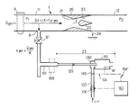
- la figure unique est une vue schématique d'un mode pardiculier de réalisation de l'invention appliqué à une zone de transit d'une conduite principale de transport ou de distribution d'un combustible gazeux et selon lequel des mesures de puissance calorifique sont effectuées à l'aide d'un circuit dérivé spécifique conformément à l'invention, une tuyère sonique à col de section variable étant mise en oeuvre dans la conduite principale de transport ou de distribution.
- the single figure is a schematic view of a particular embodiment of the invention applied to a transit zone of a main pipe for transporting or distributing a gaseous fuel and according to which calorific power measurements are made at using a specific derivative circuit in accordance with the invention, a sonic nozzle with a neck of variable section being used in the main transport or distribution pipe.
On rappellera tout d'abord que pour un combustible donné, et un air comburant défini par sa teneur en oxygène, il y a bien sûr correspondance biunivoque entre le pouvoir calorifique Pc et le volume de l'air théorique VA nécessaire à la combustion stoechiométrique de l'unité de masse selon la formule suivante :
![]()
où C est une constante.It will be recalled first of all that for a given fuel, and a combustion air defined by its oxygen content, there is of course one-to-one correspondence between the calorific power P c and the volume of the theoretical air V A necessary for combustion stoichiometric of the unit of mass according to the following formula:
![]()
where C is a constant.
Par ailleurs, il est à observer que ce rapport VA/PC varie peu avec la nature du combustible, notamment dans le cas des gaz naturels.Furthermore, it should be observed that this V A / P C ratio varies little with the nature of the fuel, in particular in the case of natural gases.
A titre d'exemple, les gaz naturels susceptibles de transiter par le réseau de distribution de Gaz de France présentent un rapport VA/PC stable à 2 pour mille près.For example, natural gases capable of transiting through the Gaz de France distribution network have a V A / P C ratio stable to 2 per thousand.
Le présente invention prend en compte la stabilité de ce rapport et permet de réaliser des mesures de puissance calorifique de façon plus simple que selon les procédés connus.The present invention takes into account the stability of this ratio and makes it possible to carry out calorific power measurements in a simpler way than according to known methods.
Pour cela, conformément au procédé selon l'invention, on met en oeuvre une combustion complète définie par son taux d'aération ou facteur d'air f, f étant défini comme le rapport du volume d'air effectivement utilisé va eu volume d'air VA nécessaire à le combustion stoechiométrique : ![]()
![]()
On rappelle que la puissance calorifique Pu est définie de le façon suivante :
![]()
où Qc est le débit massique du combustible et Pc est le pouvoir calorifique.Recall that the calorific power Pu is defined as follows:
![]()
where Qc is the mass flow of the fuel and Pc is the calorific value.
Il ressort de le combinaison des équations (1) à (3) que
![]()
Or Qc.va représente le débit massique d'air Qair effectivement utilisé ou air comburant associé au débit Qc, de sorte que l'équation (5) devient :
![]()
Dans la mesure où le facteur d'air f est maintenu constant par une régulation, la mesure du débit massique d'air comburant Qair permet de déduire directement, par un simple coefficient de proportionnalité, la valeur de la puissance calorifique.It follows from the combination of equations (1) to (3) that
![]()
Now Qc.va represents the mass flow of air Q air actually used or combustion air associated with the flow Qc, so that equation (5) becomes:
![]()
Insofar as the air factor f is kept constant by regulation, the measurement of the mass flow rate of combustion air Qair makes it possible to deduce directly, by a simple coefficient of proportionality, the value of the calorific power.
On notera alors que la valeur de f peut être choisie quelconque, bien qu'il soit avantageux de choisir une valeur du facteur d'air f égale à 1 ou voisine de 1.It will then be noted that the value of f can be chosen arbitrary, although it is advantageous to choose a value of the air factor f equal to 1 or close to 1.
Dans le cas où le facteur d'air f ne fait pas l'objet d'une régulation, celui-ci se trouve susceptible de varier notamment à l'inverse des variations du pouvoir comburivore VA du combustible considéré.In the case where the air factor f is not subject to regulation, it is likely to vary in particular contrary to variations in the comburivorous power VA of the fuel considered.
Pour déterminer le valeur de le puissance calorifique, il est alors nécessaire de mesurer le débit massique d'air qair, et le facteur d'air f, par exemple à l'aide d'une analyse de la teneur en oxygène résiduel dans les produits de la combustion.To determine the value of the calorific power, it is then necessary to measure the mass flow of air q air , and the air factor f, for example using an analysis of the residual oxygen content in the products of combustion.
La précision obtenue sur la valeur de la puissance calorifique Pu est celle observée sur la mesure du débit univoque d'air QA augmentée d'un facteur de l'ordre de 3 à 7 pour mille pour un gaz tel que le gaz "H" distribué par Gaz de France. Le facteur de 7 pour mille tient compte de la précision attendue dans le cas la régulation du facteur d'air.The precision obtained on the value of the calorific power Pu is that observed on the measurement of the unequivocal air flow QA increased by a factor of the order of 3 to 7 per thousand for a gas such as the gas "H" distributed by Gaz de France. The factor of 7 per thousand takes into account the precision expected in the case of regulating the air factor.
Selon l'invention, on réalise ainsi des mesures de puissance calorifique avec une précision qui ne dépend que de celle d'un dispositif de comptage de débit d'air, à laquelle on ajoute une incertitude de seulement quelques pour mille.According to the invention, calorific power measurements are thus carried out with an accuracy which depends only on that of an air flow metering device, to which an uncertainty of only a few per thousand is added.
Au contraire, selon les procédés classiques imposant la mesure d'un débit massique de combustible ainsi qu'une mesure de pouvoir calorifique, si la précision sur la mesure du débit massique de combustible peut être de l'ordre de grandeur de celle d'une mesure de débit messique d'air, une incertitude sur l'évaluation du pouvoir calorifique de quelques pour mille, nécessite des moyens de mesure le plus souvent dissuasifs. Le procédé selon l'invention permet donc de généraliser les mesures de puissance calorifique avec une précision comparable aux meilleurs procédés de laboratoire, tout en autorisant des mesures en continu.On the contrary, according to conventional methods imposing the measurement of a mass flow of fuel as well as a measurement of calorific value, if the precision on the measurement of the mass flow of fuel can be of the order of magnitude that of a measurement of messic air flow, an uncertainty on the evaluation of the calorific value of a few per thousand, requires means of measurement most often dissuasive. The process according to the invention therefore makes it possible to generalize the calorific power measurements with an accuracy comparable to the best laboratory methods, while allowing continuous measurements.
Un mode particulier de réalisation de l'invention sera maintenant décrit de façon plus détaillée en référence à la figure unique.A particular embodiment of the invention will now be described in more detail with reference to the single figure.
On a représenté sur le figure un mode particulier de réalisation dans lequel un comptage de débit massique d'air en vue de déterminer une puissance calorifique est effectué sur une conduite principale 1 de transport en transit d'un courant gazeux Qgaz de matière combustible, qui peut être par exemple du gaz naturel, vers une zone aval d'utilisation à pression P2 variable. Le mode de réalisation de la figure peut ainsi être appliqué à un poste de livraison de fluide combustible du transporteur au distributeur ou du distributeur à son client et permet de déterminer la puissance calorifique d'un fluide gazeux. Dans ce cas, le dispositif de mesure comprend un circuit dérivé 101 afin de prélever un débit de gaz qgaz très inférieur au débit initial Qgaz.A particular embodiment has been shown in the figure in which a mass flow rate of air is counted in order to determine a calorific power is carried out on a
Le circuit dérivé 101 permet de prélever en une zone 8 une fraction qgaz constante et très faible du débit principal de fluide combustible Qgaz afin d'alimenter à travers des canalisations de géométrie fixe une chambre de combustion annexe 110. Une chaîne 104 de régulation du facteur d'air ou 104' de mesure du facteur d'air est associée à la chambre de combustion annexe 110.The
La chaîne de régulation de facteur d'air 104 comprend une sonde 141 et un organe 140 de modulation de la quantité d'air comburant appliquée à la chambre de combustion 110 par la canalisetion 103 débouchant dans une zone 130 voisine de l'extrémité de la canalisetion dérivée 101.The air
Le capteur 141, utilisé dans le cas où le facteur d'air est régulé, peut être constitué par exemple par une sonde à détection de seuil, qui peut être avantageusement une sonde au zirconium, et qui peut présenter une précision de l'ordre de 3 à 5 pour mille.The
Comme indiqué plus haut, la chaîne 104 de régulation de facteur d'air n'est pas absolument indispensable. Si la chaîne 104 de régulation n'existe pas, celle-ci est remplacée par une chaîne de mesure 104' (représentée en traits mixtes sur la figure) qui transmet à un dispositif de calcul 160 la valeur du facteur d'air f obtenue après analyse de l'oxygène résiduel dans les produits de la combustion complète, à l'aide d'un capteur 141 qui n'est alors plus à détection de seuil mais présente une plage de mesure étendue.As indicated above, the
Un compteur de débit d'air 106 sert à la mesure du débit massique d'air comburant qair introduit par la canalisation 103 et fournit au dispositif de calcul 160 une valeur mesurée du débit massique d'air comburant utilisé pour la combustion de la fraction qgaz de fluide combustible appliquée par la canalisation 101 à la chambre de combustion annexe 110 propre au dispositif de mesure. Le dispositif 160 de calcul et d'affichage ou d'enregistrement de la puissance celorifique reçoit en entrée des informations du compteur de débit d'air 106 et le cas échéant de la chaîne 104' d'analyse du facteur d'air f.An
Le dispositif 160 peut comprendre en outre des circuits d'intégration dans le temps des valeurs de puissance calorifique calculées pour délivrer en sortie des valeurs de quantité d'énergie.The
Le dispositif 106 de mesure de débit massique d'air comprend avantageusement pour plus de précision des capteurs de mesure de température, de pression, d'hygrométrie et le cas échéant de teneur en oxygène. La connaissance de ces divers paramètres permet de déterminer avec précision en fonction du volume d'air ayant parcouru le compteur 106 par unité de temps le débit massique d'air.The
Dans la présente description on considère que l'on applique par la canalisation 103 un débit d'air comburant dont la valeur est déterminée par le dispositif de mesure 106, mais l'invention prend naturellement en compte également le cas où l'on appliquerait par la canalisation 103 de l'oxygène pur.In the present description, it is considered that a flow of oxidizing air is applied via the
Compte tenu du fait que la pression dans la zone 8 de la conduite principale 1 où prend naissance le canalisation de dérivation 101 est plus élevée que la pression dans la chambre de combustion annexe 110, une zone Z3 de la canalisation de dérivation 101 correspond de préférence à une zone de pertes de charge localisées du circuit dérivé, ce qui peut permettre un étalonnage en laboratoire du circuit dérivé.In view of the fact that the pressure in
La chambre de combustion contrôlée annexe 110 peut être réalisée de diverses manières et peut notamment être du type à combustion catalytique.The annexed controlled
Le dispositif 106 de mesure de débit massique d'air comburant peut comprendre divers composants qui sont eux mêmes classiques. Il est ainsi possible d'utiliser une pompe volumétrique basse pression, par exemple à crémeillère, pour produire et mesurer le débit de fluide gazeux.The
Dans le cas d'une conduite principale 1 de transport ou de distribution d'un fluide gazeux correspondant à une zone de transit, la géométrie ou les coefficients de débit du réseau aval varient constamment en fonction notamment du positionnement de divers éléments de robinetterie gérés par les utilisateurs et clients. Dans ce cas, le coefficient K correspondant au rapport entre le débit principal de gaz Qgaz dans la conduite principale 1 et la fraction de débit de gaz qgaz prélevée dans la cenalisation de dérivation est variable. Le mode de réalisation de la figure 3 permet de remédier à ce problème et présente diverses dispositions particulières qui permettent de s'affranchir des variations de la pression aval P2 et par suite de maintenir un rapport constant entre le débit gazeux qgaz prélevé dans le circuit 101 de dérivation et le débit principal Qgaz circulent dans la conduite principale 1.In the case of a
Dans le mode de réalisation de le figure, une tuyère sonique 20 a été disposée dans la conduite principale 1 pour définir un tronçon de conduite amont 11 et un tronçon de conduite aval 12. La tuyère sonique convergente divergente 20 comporte un col 21 de section fixe et détermine un débit de gaz Qd dans la conduite principale 1 qui est indépendant de le pression aval P2 et ne dépend que de la pression amont P1, de la section du col 21 de la tuyère 20 et bien sûr des caractéristiques du fluide (densité, viscosité,...).In the embodiment of the figure, a
Le circuit de dérivation 101 comprend lui-même une tuyère 120 à col sonique et le circuit dérivé 101 est raccordé à la conduite principale 1 immédiatement en amont de la tuyère 20 placée sur le circuit principal, dans une zone 8 du tronçon amont 11 de la conduite principale 1.The
Le circuit de dérivation 101 comprend au voisinage de la zone 8 de raccordement à la conduite principale 1 un robinet 81 à passage direct ne donnant pas lieu à des pertes de charge significatives et peut aussi comporter un filtre 109 également à pertes de charge non significatives. Le circuit dérivé 101 est à géométrie fixe et comporte une zone Z3 à localisation des pertes de charge, dans laquelle est disposée la tuyère 120 à col fixe.The
Le circuit dérivé 101 débouche dans une chambre de combustion annexe 110 qui peut être par exemple du type à combustion catalytique, à laquelle est associée une chaîne 104 de régulation de facteur d'air ou 104' de mesure du facteur d'air et qui est équipée d'une conduite 103 d'alimentation d'air comburant sur laquelle est disposé un dispositif 106 de mesure de débit massique d'air qair associé à un dispositif de calcul et d'affichage 160. Un filtre 9 sans pertes de charge significatives peut également être disposé sur la conduite principale 1 en amont de la zone 8 dans laquelle prend naissance le circuit de dérivation 101.The
Avec le dispositif de mesure représenté sur la figure, il est possible de déterminer une puissance calorifique avec une grande précision à partir de la mesure de débit d'air effectuée par le dispositif de mesure 106, sous réserve de disposer d'une chaîne 104 de régulation ou 104' de mesure de facteur d'air précise et de déterminer également avec précision le rapport des sections de la tuyère principale 20 et de la tuyère secondaire 120. Le rapport de ces sections peut être déterminé lors du montage ou peut être déterminé par étalonnage du circuit principal et du circuit dérivé. La présence d'un robinet 81 permet de réaliser l'étalonnage du circuit dérivé d'une façon commode.With the measuring device shown in the figure, it is possible to determine a calorific power with great precision from the measurement of air flow rate carried out by the measuring
On notera que la mesure du débit d'air qair à l'aide du dispositif 106 porte sur une valeur relativement peu variable dès lors que le raccordement du circuit dérivé 101 est effectué en une zone 8 où la pression P1 dans la conduite principale est relativement stable. Ceci permet un meilleur choix du calibre du compteur de débit massique d'air et donc une précision optimale.It will be noted that the measurement of the air flow q air using the
Dans le cas du mode particulier de réalisation représenté sur la figure, le tuyère principale 20 disposée dans le conduite principale 1 est de type sonique mais présente un col 21 à section variable du fait de la présence d'une ogive 22 disposée axialement à l'intérieur du corps 23 de le tuyère 20. Dans ce cas, la tuyère sonique à col variable 20 peut présenter une fonction de régulation de la pression aval P2 et peut également constituer un compteur du débit de fluide combustible gazeux par courent la conduite principale 1.In the case of the particular embodiment shown in the figure, the
Dans le mesure où la section du col de le tuyère 20 est variable en fonction de la position de l'ogive mobile 22 selon l'axe de la tuyère, le rapport entre le débit de gaz dans la conduite principale 1 et le débit de gaz dérivé dans le circuit de dérivation 101 est fonction de la position de l'ogive 22. Par suite, le coefficient de proportionnalité entre la valeur du débit d'air comburant mesuré par le dispositif de mesure 106 et la puissance calorifique distribuée dans la conduite principale 1 est lui-même dépendant de la position de l'ogive mobile 22. Le position de l'ogive 22 peut toutefois être déterminée avec précision en permanence par exemple à l'aide d'un organe de repérage 24 solidaire de l'ogive 22. En effectuant un étalonnage préalable, il est facile de déterminer l'évolution du coefficient de proportionnalité et ainsi de déterminer la puissance calorifique distribuée, à partir du débit d'air mesuré, et du repérage de le position l de l'ogive 22 selon l'axe de la tuyère 20.Insofar as the section of the neck of the
Le mode de réalisation représenté sur la figure permet ainsi de combiner un dispositif de mesure calorifique avec un régulateur compteur tel que par exemple celui qui est décrit dans le brevet français 2 341 131.The embodiment shown in the figure thus makes it possible to combine a calorific measurement device with a counter regulator such as for example that which is described in French patent 2,341,131.
Dans le cas du mode de réalisation décrit, il est bien sûr aussi possible d'utiliser divers dispositifs, par exemple de type pneumatique, pour maintenir constant, ou mesurer en permanence, le coefficient K de répartition du débit Qgaz du fluide combustible entre la branche principale de la conduite 1 et le circuit dérivé 101 prenant naissance dans le zone 8 de la conduite principale 1. En particulier, si l'on dispose d'un dispositif de mesure de comptage du débit massique du gaz Qgaz dans la conduite principale 1, il est possible de déterminer le facteur K de proportionnelité entre le débit Qgaz et le débit dérivé qgaz en effectuant une mesure du débit de gaz dérivé qgaz. Cette mesure du débit de gaz dérivé qgaz peut être effectuée de manière préférentielle soit grâce à la mise en oeuvre d'une tuyère à col fixe, notamment si l'on dispose d'un point de raccordement à pression régulée, soit en fin de circuit dérivé 101, immédiatement avant la combustion contrôlée dans la chambre 110, pour bénéficier des avantages du point de vue de la précision, des coûts et d'un comptage dans les conditions proches de l'ambiance.In the case of the embodiment described, it is of course also possible to use various devices, for example of the pneumatic type, to maintain constant, or permanently measure, the coefficient K of distribution of the flow rate Q gas of the combustible fluid between the main branch of
Dans le cas de l'utilisation d'un circuit dérivé, on procède à une localisation et une répartition des pertes de charge du circuit dérivé pour permettre le cas échéant un étalonnage des deux circuits principal et dérivé pris séparément et un dimensionnement et un fonctionnement optimisés de la tuyère 120 placée dans le circuit dérivé 101.In the case of the use of a branch circuit, a localization and distribution of the pressure drops of the branch circuit is carried out to allow, if necessary, a calibration of the two main and branch circuits taken separately and an optimized dimensioning and operation. of the
On notera qu'un circuit dérivé unique 101 pourrait être associé à plusieurs circuits principaux de transport de fluide combustible présentant des calibres différents et donc équipés de tuyères de calibres différents, sous réserve que chacune des conduites principales de celibres différents soient équipées d'un robinet automatique à passage direct n'introduisant pas de perte de charges significatives et permettant un raccordement par alternance aux divers tronçons de conduites de calibres différents. Ceci peut notamment permettre d'accroître la précision des mesures de puissance calorifique en choisissent à chaque fois le calibre le plus approprié.It will be noted that a single
On notera que dans tous les modes de réalisation qui viennent d'être décrits les débits massiques d'air mesurés par le dispositif de mesure 106 sont mesurés dans des conditions proches des conditions ambiantes ce qui est particulièrement avantageux, du fait notamment qu'il est possible de disposer de nombreux matériels pouvant s'adapter aux diverses conditions de mesure.It will be noted that in all of the embodiments which have just been described, the mass air flow rates measured by the measuring
Claims (13)
- Measuring apparatus for measuring the calorific power conveyed by a flow, in particular a gas flow, of fuel substance flowing along a main duct (1) for transit transport or distribution of a gaseous flow of fuel substance towards a downstream utilization zone at variable pressure, comprising a combustion chamber (110) specific to the measuring apparatus for buming a small known fraction (qgas) of the mass flow rate (Qgas) of the fuel substance flowing along the duct (1), and a system (104, 104') for measuring the air factor (f) applied to said combustion chamber (110) or for regulating the combustion in said combustion chamber (110) in order to maintain a constant air factor (f),
characterized in that it comprises a main nozzle (20) having a sonic throat of variable cross-section which is disposed in the main duct (1), and a branch circuit (101) for taking a small known fraction (qgas) of the mass flow rate (Qgas) of the gaseous flow flowing along the main duct (1) in order to apply said small fraction (qgas) to said controlled combustion chamber (110), in that the branch circuit (101) lies in a zone (8) of the main duct (1) situated upstream from the main nozzle (20) and comprises a secondary nozzle (120) whose sonic throat is of fixed geometry, in that the combustion chamber (110) of the branch circuit is fed with oxidizing air via a pipe (103) in which a meter device (106) is mounted to measure the mass flow rate (qair) of the oxidizing air used for combustion of the fraction (qgas) and applied to said combustion chamber (110) and in that it comprises computing and display or recording means (160) connected to said meter device (106) and to said system (104, 104') for measuring or regulating the air factor (f) in order to determine and display or record the value of the calorific power (Pu) of the substance flowing along said main duct (1) on the basis of data concerning the mass flow rates (qair) of the oxidizing air delivered by said meter device (106) and data concerning the air factor (f) delivered by said measuring or regulation system (104, 104'). - Apparatus according to claim 1, characterized in that the main nozzle (20) with a sonic throat and providing a downstream pressure regulation function has a throat whose flow section is variable and defined by the position of a moving cone (22) disposed inside the body of the nozzle (22) and moveable in translation along the axis of the nozzle relative to said throat, and in that a position sensor (24) is used to detect the displacement and the position of the moving cone (22) in order to provide the computing and display means (160) with data concerning the longitudinal position of said cone (22).
- Apparatus according to any one of claims 1 and 2, characterized in that the branch circuit (101) has portions of reduced cross-section giving rise to localized head losses (zone Z2 or Z3).
- Apparatus according to any one of claims 1 and 2, characterized in that the main duct (1) is provided with a filter (9) disposed upstream from the zone (8) for connecting the branch circuit (101) to the main duct (1).
- Apparatus according to any one of claims 1 and 2, characterized in that the branch circuit (101) is provided with a second filter (109) having no significant head losses and disposed upstream from the zone (Z3) in which head losses are localized.
- Apparatus according to any one of claims 1 and 2, characterized in that the branch circuit (101) is fitted with a through passage tap (81) disposed at the inlet to said circuit (101).
- Apparatus according to any one of claims 1 and 2, characterized in that the controlled combustion chamber (110) is of the catalytic combustion type.
- Apparatus according to any one of claims 1 to 7, characterized in that the meter device (106) for measuring the air mass flow rate comprises a low pressure positive displacement pump.
- Apparatus according to any one of claims 1 to 8, characterized in that it includes a device for detecting variations in the combustion air factor, said device comprising a threshold probe for measuring the residual oxygen in the combustion products.
- Apparatus according to any one of claims 1 to 9, characterized in that the meter device (106) for measuring the oxidizing air mass flow rate includes means for measuring volume, temperature, pressure, and humidity of the oxidizing air applied to the combustion chamber (110) specific to the apparatus.
- Apparatus according to any one of claims 1 to 8, characterized in that the system (104') for measuring the air factor (f) includes means for analyzing the oxygen content of the combustion products coming from the combustion chamber (110) specific to the apparatus.
- Apparatus according to claim 11, characterized in that the meter device (106) for measuring the oxidizing air mass flow rate also includes means for analyzing the oxygen content of the oxidizing air, and in that said means for analyzing the oxygen content are constituted by a single oxygen content analyzer applied in alternation to the ducts for exhausting the combustion products and to the duct (103) for supplying the oxidizing air.
- Apparatus according to any one of claims 1 to 12, characterized in that the computing and display or recording means (160) connected to the meter device (106) and to the system (104, 104') for measuring or regulating the air factor (f) include circuits for integrating the calculated calorific power over time in order to deliver an output representative of a total quantity of energy.
Priority Applications (1)
| Application Number | Priority Date | Filing Date | Title |
|---|---|---|---|
| AT89400233T ATE94987T1 (en) | 1988-01-29 | 1989-01-27 | DEVICE FOR MEASURING THE THERMAL CAPACITY OF A FLOW OF FUEL. |
Applications Claiming Priority (2)
| Application Number | Priority Date | Filing Date | Title |
|---|---|---|---|
| FR888801086A FR2626673B1 (en) | 1988-01-29 | 1988-01-29 | METHOD AND DEVICE FOR MEASURING THE HEAT POWER OF A VEHICLE BY A FUEL CURRENT |
| FR8801086 | 1988-01-29 |
Publications (2)
| Publication Number | Publication Date |
|---|---|
| EP0326494A1 EP0326494A1 (en) | 1989-08-02 |
| EP0326494B1 true EP0326494B1 (en) | 1993-09-22 |
Family
ID=9362781
Family Applications (1)
| Application Number | Title | Priority Date | Filing Date |
|---|---|---|---|
| EP89400233A Expired - Lifetime EP0326494B1 (en) | 1988-01-29 | 1989-01-27 | Apparatus for measuring the calorific power carried by a flow of combustible matter |
Country Status (7)
| Country | Link |
|---|---|
| EP (1) | EP0326494B1 (en) |
| JP (1) | JP2792881B2 (en) |
| AT (1) | ATE94987T1 (en) |
| CA (1) | CA1325343C (en) |
| DE (1) | DE68909260T2 (en) |
| FR (1) | FR2626673B1 (en) |
| NO (1) | NO302444B1 (en) |
Families Citing this family (20)
| Publication number | Priority date | Publication date | Assignee | Title |
|---|---|---|---|---|
| NL8901660A (en) * | 1989-06-30 | 1991-01-16 | Nederlandse Gasunie Nv | METHOD AND APPARATUS FOR DETERMINING THE WOBBE INDEX. |
| NL9000449A (en) * | 1990-02-24 | 1991-09-16 | Nederlandse Gasunie Nv | METHOD AND APPARATUS FOR DETERMINING THE WOBBE INDEX. |
| FR2664975A1 (en) * | 1990-07-23 | 1992-01-24 | Methane Cie Francaise | METHOD AND DEVICE FOR COUNTING COMBUSTIBLE GAS. |
| US5201581A (en) * | 1991-11-18 | 1993-04-13 | Badger Meter, Inc. | Method and apparatus for measuring mass flow and energy content using a linear flow meter |
| US5323657A (en) * | 1991-11-04 | 1994-06-28 | Badger Meter, Inc. | Volumetric flow corrector and method |
| GB9219257D0 (en) * | 1992-09-11 | 1992-10-28 | Marconi Gec Ltd | Energy measurement |
| US5357809A (en) * | 1993-04-14 | 1994-10-25 | Badger Meter, Inc. | Volumetric flow corrector having a densitometer |
| US5820260A (en) * | 1996-07-12 | 1998-10-13 | Badger Meter, Inc. | Measuring heating value using predetermined volumes in non-catialytic combustion |
| US5816705A (en) * | 1996-07-12 | 1998-10-06 | Badger Meter, Inc. | Measuring heating value of a gas using flameless combustion |
| FR2788839B1 (en) | 1999-01-22 | 2001-04-20 | Saint Gobain Vitrage | METHOD AND DEVICE FOR REGULATING A GAS FUEL CURRENT |
| NL1014749C2 (en) * | 2000-03-24 | 2001-09-25 | Petrocare B V | Measuring hydrocarbon content of a gas flow with a flow meter and calorific value determining device, by passing gas through a venturi |
| CN100516808C (en) * | 2005-04-22 | 2009-07-22 | 中国科学院力学研究所 | Air heating system |
| GB2454202B (en) * | 2007-10-31 | 2011-03-23 | Anubiz Bvba | Method for determining the heating value of a hydrocarbon fuel and apparatus for the same |
| FR3030034A1 (en) * | 2014-12-12 | 2016-06-17 | Sagemcom Energy & Telecom Sas | GAS COUNTER, GAS DISTRIBUTION SYSTEM, AND GAS DISTRIBUTION METHOD |
| JP6476340B1 (en) * | 2018-09-28 | 2019-02-27 | 東芝プラントシステム株式会社 | By-product gas measurement system |
| JP6770622B1 (en) * | 2019-09-24 | 2020-10-14 | 東京瓦斯株式会社 | Calorimeter, calorimeter measurement method |
| DE102019129430B4 (en) * | 2019-10-31 | 2021-08-12 | AVX/KUMATEC Hydrogen GmbH & Co. KG | Method and device for the continuous determination of the mixing ratio of flammable and oxidative gases in an explosive high-pressure environment and arrangement |
| JP6808885B1 (en) * | 2020-08-31 | 2021-01-06 | 東京瓦斯株式会社 | Calorimeter and calorimeter measurement method |
| CN112946232A (en) * | 2021-02-04 | 2021-06-11 | 成都秦川物联网科技股份有限公司 | Natural gas energy metering data acquisition method and system |
| EP4050258A1 (en) * | 2021-02-26 | 2022-08-31 | Siemens Aktiengesellschaft | Performance determination of a gas burner unit based on a fuel parameter |
Family Cites Families (9)
| Publication number | Priority date | Publication date | Assignee | Title |
|---|---|---|---|---|
| GB1056540A (en) * | 1963-10-26 | 1967-01-25 | Vyzkumney Ustav Energeticky Of | Method of and apparatus for measurement of calorific values |
| EP0031145B1 (en) * | 1979-12-20 | 1985-01-16 | Honeywell Inc. | Method and apparatus for determining the volumetric heat content of gaseous fuels |
| DE3275237D1 (en) * | 1981-03-17 | 1987-02-26 | Honeywell Inc | A COMBUSTIBLE GAS ANALYZER |
| CA1180917A (en) * | 1981-05-22 | 1985-01-15 | Westinghouse Electric Corporation | Btu meter for monitoring the heating value of fuel gases |
| US4415278A (en) * | 1982-02-08 | 1983-11-15 | Honeywell Inc. | Method for operating a gas analyzing system and apparatus utilizing the same |
| US4433922A (en) * | 1982-07-02 | 1984-02-28 | The Babcock & Wilcox Company | Calorimeter |
| US4511262A (en) * | 1982-10-06 | 1985-04-16 | Honeywell Inc. | Fuel entrained oxygen compensation for calorific content analyzer |
| FR2564591B1 (en) * | 1984-05-18 | 1988-01-15 | Siderurgie Fse Inst Rech | COMBURIMETER AND METHODS OF USE FOR DETERMINING FUEL POWER AND THE FUEL COMBURITY INDEX |
| DE3542377A1 (en) * | 1985-11-30 | 1987-06-04 | Porsche Ag | METHOD FOR DETERMINING THE STOECHIOMETRIC AIR AMOUNTS OF FUELS |
-
1988
- 1988-01-29 FR FR888801086A patent/FR2626673B1/en not_active Expired - Lifetime
-
1989
- 1989-01-24 NO NO890291A patent/NO302444B1/en not_active IP Right Cessation
- 1989-01-27 AT AT89400233T patent/ATE94987T1/en active
- 1989-01-27 CA CA000589409A patent/CA1325343C/en not_active Expired - Lifetime
- 1989-01-27 DE DE89400233T patent/DE68909260T2/en not_active Expired - Fee Related
- 1989-01-27 EP EP89400233A patent/EP0326494B1/en not_active Expired - Lifetime
- 1989-01-30 JP JP1020690A patent/JP2792881B2/en not_active Expired - Fee Related
Also Published As
| Publication number | Publication date |
|---|---|
| NO302444B1 (en) | 1998-03-02 |
| ATE94987T1 (en) | 1993-10-15 |
| FR2626673A1 (en) | 1989-08-04 |
| CA1325343C (en) | 1993-12-21 |
| DE68909260D1 (en) | 1993-10-28 |
| DE68909260T2 (en) | 1994-03-10 |
| EP0326494A1 (en) | 1989-08-02 |
| JP2792881B2 (en) | 1998-09-03 |
| FR2626673B1 (en) | 1994-06-10 |
| NO890291D0 (en) | 1989-01-24 |
| NO890291L (en) | 1989-07-31 |
| JPH01233355A (en) | 1989-09-19 |
Similar Documents
| Publication | Publication Date | Title |
|---|---|---|
| EP0326494B1 (en) | Apparatus for measuring the calorific power carried by a flow of combustible matter | |
| EP1060348B1 (en) | Device for actively regulating air/gas ratio in a burner comprising a differential pressure measuring device | |
| EP0664449B1 (en) | Process and apparatus for feeding gas to a gas impurity trace analyser | |
| EP0527678B1 (en) | Method for measuring the flow rate of fluidised powder and flow rate measuring device utilising this method | |
| EP3563152B1 (en) | Method for estimating a combustion characteristic of a gas containing hydrogen | |
| CA2052496A1 (en) | Process and device for gas feeding a highly sensitive analyser | |
| FR3019300A1 (en) | TEST BENCH, INTENDED FOR THE CHARACTERIZATION OF A FLOW OF A DIPHASIC FLUID. | |
| FR2509854A1 (en) | MEASUREMENT METHOD FOR DETERMINING THE MASS FLOW OF COMBUSTIBLE MATERIALS IN THE FORM OF POWDER AND PELLETS | |
| WO1997006095A1 (en) | Process for the recovery of steam emitted in a liquid distribution plant | |
| FR2791091A1 (en) | METHOD AND DEVICE FOR REGULATING THE FRACTION OF RECYCLED EXHAUST GASES IN AN ENGINE | |
| EP0660091A1 (en) | Method and device for metering gas under pressure | |
| CA2988508C (en) | Device and method for injecting dihydrogen into a flow of natural gas originating from a first natural gas distribution network | |
| FR2784747A1 (en) | METHOD AND DEVICE FOR MEASURING THE QUANTITY OF IMPURITIES IN A GAS SAMPLE TO BE ANALYZED | |
| EP0296911B1 (en) | Electronic testing bench for the rapid calibration of water meters | |
| EP1045246A1 (en) | Evaluation and regulation of the thermal power of a stream of combustible gas, and characterization of thermal mass flowmeter | |
| CA2029212A1 (en) | Control device of a ventilation power regulating station in a controlled atmosphere room and operating cycle thereof | |
| CA2432895C (en) | Method and device for evaluating a fuel gas wobbe index | |
| FR2777878A1 (en) | Vapor recovery method for a fuel dispensing installation used to deliver fuel to a motor vehicle | |
| EP0661499B1 (en) | Real time control of a burner for gases with differing characteristices, especially for a metallurgical furnace for reheating | |
| EP0468872B1 (en) | Apparatus for metering flammable gas | |
| FR3135137A1 (en) | Ultrasonic fluid meter integrating two pressure sensors. | |
| EP1635117A1 (en) | Method for regulating the air/fuel ratio of a burner and burner using this method | |
| FR2623617A1 (en) | DEVICE FOR MEASURING A FLUID FLOW IN A PIPE | |
| NL8901660A (en) | METHOD AND APPARATUS FOR DETERMINING THE WOBBE INDEX. | |
| EP0909888B1 (en) | Method for monitoring the operability and ageing of a linear oxygen sensor |
Legal Events
| Date | Code | Title | Description |
|---|---|---|---|
| PUAI | Public reference made under article 153(3) epc to a published international application that has entered the european phase |
Free format text: ORIGINAL CODE: 0009012 |
|
| AK | Designated contracting states |
Kind code of ref document: A1 Designated state(s): AT BE CH DE ES GB GR IT LI LU NL SE |
|
| 17P | Request for examination filed |
Effective date: 19900118 |
|
| 17Q | First examination report despatched |
Effective date: 19910402 |
|
| GRAA | (expected) grant |
Free format text: ORIGINAL CODE: 0009210 |
|
| AK | Designated contracting states |
Kind code of ref document: B1 Designated state(s): AT BE CH DE ES GB GR IT LI LU NL SE |
|
| PG25 | Lapsed in a contracting state [announced via postgrant information from national office to epo] |
Ref country code: AT Effective date: 19930922 Ref country code: ES Free format text: THE PATENT HAS BEEN ANNULLED BY A DECISION OF A NATIONAL AUTHORITY Effective date: 19930922 Ref country code: GR Free format text: LAPSE BECAUSE OF FAILURE TO SUBMIT A TRANSLATION OF THE DESCRIPTION OR TO PAY THE FEE WITHIN THE PRESCRIBED TIME-LIMIT Effective date: 19930922 Ref country code: SE Effective date: 19930922 |
|
| REF | Corresponds to: |
Ref document number: 94987 Country of ref document: AT Date of ref document: 19931015 Kind code of ref document: T |
|
| REF | Corresponds to: |
Ref document number: 68909260 Country of ref document: DE Date of ref document: 19931028 |
|
| ITF | It: translation for a ep patent filed |
Owner name: JACOBACCI CASETTA & PERANI S.P.A. |
|
| GBT | Gb: translation of ep patent filed (gb section 77(6)(a)/1977) |
Effective date: 19931115 |
|
| PG25 | Lapsed in a contracting state [announced via postgrant information from national office to epo] |
Ref country code: LU Free format text: LAPSE BECAUSE OF NON-PAYMENT OF DUE FEES Effective date: 19940131 Ref country code: LI Effective date: 19940131 Ref country code: CH Effective date: 19940131 |
|
| PLBE | No opposition filed within time limit |
Free format text: ORIGINAL CODE: 0009261 |
|
| STAA | Information on the status of an ep patent application or granted ep patent |
Free format text: STATUS: NO OPPOSITION FILED WITHIN TIME LIMIT |
|
| 26N | No opposition filed | ||
| REG | Reference to a national code |
Ref country code: CH Ref legal event code: PL |
|
| REG | Reference to a national code |
Ref country code: GB Ref legal event code: IF02 |
|
| PGFP | Annual fee paid to national office [announced via postgrant information from national office to epo] |
Ref country code: NL Payment date: 20020116 Year of fee payment: 14 |
|
| PGFP | Annual fee paid to national office [announced via postgrant information from national office to epo] |
Ref country code: DE Payment date: 20020118 Year of fee payment: 14 |
|
| PG25 | Lapsed in a contracting state [announced via postgrant information from national office to epo] |
Ref country code: NL Free format text: LAPSE BECAUSE OF NON-PAYMENT OF DUE FEES Effective date: 20030801 Ref country code: DE Free format text: LAPSE BECAUSE OF NON-PAYMENT OF DUE FEES Effective date: 20030801 |
|
| NLV4 | Nl: lapsed or anulled due to non-payment of the annual fee |
Effective date: 20030801 |
|
| PGFP | Annual fee paid to national office [announced via postgrant information from national office to epo] |
Ref country code: GB Payment date: 20071227 Year of fee payment: 20 |
|
| PGFP | Annual fee paid to national office [announced via postgrant information from national office to epo] |
Ref country code: IT Payment date: 20080123 Year of fee payment: 20 |
|
| PGFP | Annual fee paid to national office [announced via postgrant information from national office to epo] |
Ref country code: BE Payment date: 20080124 Year of fee payment: 20 |
|
| REG | Reference to a national code |
Ref country code: GB Ref legal event code: PE20 Expiry date: 20090126 |
|
| PG25 | Lapsed in a contracting state [announced via postgrant information from national office to epo] |
Ref country code: GB Free format text: LAPSE BECAUSE OF EXPIRATION OF PROTECTION Effective date: 20090126 |