EP0325864A2 - Gegenschwerkraft-Giesseinrichtung - Google Patents
Gegenschwerkraft-Giesseinrichtung Download PDFInfo
- Publication number
- EP0325864A2 EP0325864A2 EP88312384A EP88312384A EP0325864A2 EP 0325864 A2 EP0325864 A2 EP 0325864A2 EP 88312384 A EP88312384 A EP 88312384A EP 88312384 A EP88312384 A EP 88312384A EP 0325864 A2 EP0325864 A2 EP 0325864A2
- Authority
- EP
- European Patent Office
- Prior art keywords
- mould
- molten metal
- vacuum
- countergravity casting
- cavity
- Prior art date
- Legal status (The legal status is an assumption and is not a legal conclusion. Google has not performed a legal analysis and makes no representation as to the accuracy of the status listed.)
- Granted
Links
Images


Classifications
-
- B—PERFORMING OPERATIONS; TRANSPORTING
- B22—CASTING; POWDER METALLURGY
- B22D—CASTING OF METALS; CASTING OF OTHER SUBSTANCES BY THE SAME PROCESSES OR DEVICES
- B22D18/00—Pressure casting; Vacuum casting
- B22D18/06—Vacuum casting, i.e. making use of vacuum to fill the mould
Definitions
- This invention relates to apparatus for the vacuum, countergravity casting of metal in gas-permeable, shell moulds as specified in the preamble of claim 1, for example as disclosed in US-A-4,616,691, and, more particularly, to means for anchoring the mould to the vacuum chamber used therewith.
- the vacuum, countergravity, shell mould casting process is particularly useful in the making of thin-walled castings and involves: sealing a bottom-gated mould, having a gas-permeable upper portion, to the mouth of a vacuum chamber such that the chamber confronts the upper portion; immersing the underside of the mould in an underlying melt; and evacuating the chamber to draw melt up into the mould through one or more gates in the underside thereof.
- a process is shown in United States patent 4,340,108 wherein the mould comprises a resin-bonded-sand shell having an upper cope portion and a lower drag portion sealingly bonded together and attached to the vacuum chamber by means of spring clips which engage a peripheral abutment on the outside of the vacuum chamber.
- United States patent 4,340,108 seals the mould to the vacuum chamber on top of the cope such that the parting line between the mould halves lies outside the vacuum chamber.
- United States patent 4,632,171 seals the mould to the vacuum chamber on top of the drag such that the parting line between the cope and drag falls within the vacuum chamber.
- United States patent 4,632,171 uses spring-biased bolts engaging the underside of the drag and extending along the outside of the vacuum chamber to secure the mould to the vacuum chamber. The heads of the bolts are immersed in the melt and accordingly have a very short useful life. G.D.
- An apparatus for the vacuum countergravity casting of molten metal according to the present invention is characterised by the features specified in the characterising portion of claim 1.
- the invention comprehends an improved vacuum, countergravity casting apparatus including: a mould having a porous, gas-permeable upper shell and a bottom-gated lower portion secured to the upper shell; a vacuum box defining a chamber confronting the upper shell for evacuating the mould through the shell, which box comprises a peripheral wall having a lip on the underside thereof for sealingly engaging the mould and a ceiling overlying the mould; a plurality of anchoring cavities recessed in the mould, each of which is defined in part by at least one shelf-like, overhang portion(s) of the mould overlying the anchoring cavity; an opening in the mould contiguous the overhang providing access to the anchoring cavity; and anchoring means reciprocably slidable through the ceiling of the box, which anchoring means comprises (1) a plurality of shafts extending through the ceiling of the box, (2) a keeper on the lower end(s) of each shaft adapted for insertion through the opening(s) in the mould and into the cavity(s) and rotation therein to engage the underside(s
- the anchoring cavity is preferably defined by two overhang portions which flank the access opening to the cavity.
- the keeper is preferably an elongated bar welded or otherwise secured to the lower end of the shaft midway on the bar so that, upon 90° rotation of the shaft, one half of the bar engages the underside of one of the overhangs and the other half of the bar engages the underside of the other overhang. All the shafts will preferably be appropriately mechanically linked or pneumatically/hydraulically coupled together for simultaneous/en masse rotation.
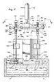
- the several Figures show a pot 2 of metal melt 4 which is to be drawn up into a mould 6.
- the mould 6 includes a gas-permeable, upper portion 8 secured (e.g., glued) to a lower portion 10 along parting line 12 and a moulding cavity 16 therebetween.
- the lower portion 10 includes a plurality of ingates 14 on the underside thereof for supplying melt to the mould cavity 16 when the cavity is evacuated.
- the lower portion 10 of the mould 6 is sealed (i.e., via a high temperature gasket material 24) to a mouth 18 of a vacuum chamber 20 which is defined by vacuum box 22 such that the gas-permeable upper portion 8 of the mould 6 is contained within the chamber 20.
- the vacuum chamber 20 communicates with a vacuum source (not shown) via conduit 23.
- the upper (i.e., cope) portion 8 of the mould 6 comprises a gas-permeable material (e.g., resin-bonded-sand, or a ceramic, material) which permits gases to be withdrawn from the casting cavity 16 when a vacuum is established in the chamber 20.
- the lower portion 10 of the mould 6 may conveniently comprise the same material as the upper portion 8, or other materials, permeable or impermeable, which are compatible with the upper portion material.
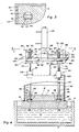
- each of the anchoring means 30 comprises an axially and rotatably movable shaft 34 having an elongated keeper bar 28 secured at about its centre onto the lower end of the shaft 34.
- the keeper bar 24 passes through an elongated, substantially complementary-shaped, access opening 36 to the cavity 26 in the mould 6.
- the opening 36 is flanked on both sides by portions 38 of the mould 6 which overhang and partially define the respective cavity 26.
- the keeper bars 28 are rotated under the overhang portions 38 to engage undersides 40 of the overhang portions 38.
- a single overhang and a keeper comprising a half-bar, as it were, secured at its end to the shaft 34 may also be used to engage a single overhang portion.
- the full bar keeper and dual overhang shown is preferred for providing the most reliable anchoring.
- the several anchoring means 30 are each manually operated so as to mate with the several anchoring cavities 26 one at a time.
- a handle 42 is provided on the end of the shaft 34 opposite the keeper 28.
- the shaft 34 slides through an elongated bushing 44 welded to the ceiling 32 of the box 22 which serves not only to keep the shaft registered with the openings 36 but also to prevent any significant loss of vacuum from the chamber 20 along the shaft 34.
- Compression springs 46 are provided between the bushing 44 and the handle 42 to bias the mould 6 tightly against the mouth 18 of the box 22 after the keepers 28 have been inserted through the openings 36 into the respective cavities 26 and rotated under the overhanging ledges 38.
- the anchoring means 30 on the left side of the drawing is shown in the anchoring position engaging the overhang portions 38 whilst on the right side of the drawing, the anchoring means 30 is shown positioned above the opening 36 prior to insertion therein.
- linkage means 50 adapted to engage/disengage the several keepers with/from the mould en masse.
- linkage means 50 includes a frame comprising support members 52 secured to and carried by a tubular steel cross-member 54 via brackets 56.
- An air cylinder 58 is detachably secured (e.g., bolted) to the centre of the cross-member 54 via a mounting bar 60 to raise and lower the linkage means 50 as required to engage/disengage the keepers 28 from the mould 6.
- the shafts 34 are axially slidable through bushings 62 which are fitted for rotation in the ends 64 of the support members 52.
- Yokes 66 include upper arms 68 fixed securely, but adjustably, to upper ends 70 of the respective shafts 34 and lower arms 72 which may be threaded onto threads 74 on the respective shafts 34. Compression springs 76 bias the yokes 66 upwardly relative to the supports 52 to hold the mould firmly, yet resiliently, in place in the chamber 20. Bushings 102 secured to the top of the box 22 permit the shafts 34 to slide axially therethrough as well as rotate therein without substantially reducing the vacuum in the chamber 20.
- the air cylinder 58 is energized to extend the rod 59 to as to move the support members 52 downwardly which in turn push on the lower arms 72 of the yokes 66. This causes the shafts 34 to slide axially in the bushings 102 to insert the keepers 28 in the respective openings 36 above the cavities 26.
- Toggles 90 and 92 and lever arms 98 and 100 are rigidly secured to the respective bushings 62 so as to effect rotation thereof when the toggles 90, 92 are moved.
- an air cylinder 80 which is rigidly anchored to the cross member 54 via support arm 82, is energized to retract a cylinder rod 84.
- link 86 which is attached thereto at joint 88 also moves to the left and causes the toggles 90 and 92 to rotate clockwise 90°.
- shorter links 94 and 96 which are rotatably coupled to the toggles 90 and 92, act on lever arms 98 and 100 to also rotate them through 90°.
- Figure 6 depicts still another embodiment of the present invention wherein individual air motors 110 on the upper ends of each of the shafts 34 are actuated substantially simultaneously from a common air source (not shown) to both insert the keepers 28 in the anchoring cavities 26 as well as rotate them therein for anchoring the mould in the chamber 20.
- the keepers 28 engage cavities 26 formed in upstanding portions 112 formed on a drag portion 114 of the mould 6.
- Caps 116 having keeper-receiving openings 118 therein are glued or otherwise secured on top of the upstanding portions 112 to provide the requisite cavity overhanging portions needed to engage the keepers 28.
- Figures 7 and 8 depict another embodiment of the present invention wherein the means for anchoring the mould to the vacuum chamber lie on the outside of (i.e., outboard) the chamber, the anchoring cavities are formed from the underside of the bottom portion of the mould and the mouth of the anchoring cavity (i.e., where it opens to the underside of the mould) is plugged with mould material or similar material to protect the keeper from the deleterious effects of the melt when the mould is immersed therein. More specifically, the Figures shown a lower portion 120 of the mould secured to an octagonal vacuum chamber 122 and immersed in the melt 4 in the pot 2.
- the lower portion 120 includes four towers 124 extending upwardly from the corners of the mould for housing anchoring cavities 126 which are formed in the towers 124 from the underside 128 of the lower mould portion 120. Forming the cavities from the underside of the mould simplifies the cavity-forming process and particularly eliminates the need for a separate cap such as cap 116 in Fig. 6.
- the mouth 130 of each cavity 126 where it opens to the underside of the mould 128 is preferably closed-off with a plug of mould material 132 to protect a respective keeper 134 from contacting the melt 4.
- An upstanding levee 136 circumscribes the junction between the chamber 122 and the lower portion 120 of the mould to protect the junction from the melt as described and claimed in U.S. patent 4,745,962.
- the anchoring means 30 is adapted to engage the bottom portion 120 of the mould on the outside of the vacuum chamber 122. More specifically, shafts 138 of the anchoring means 30 reciprocate and rotate in ball-bushings 140 and guide rings 142 which stabilize and guide the shafts 138 and keepers 134 into respective openings 144 to the cavities 126. Flexible couplings (e.g., U-joints) 146 on the upper ends of the shafts 138 allow for any misalignment between the shafts 138 and the actuating means 148 and thereby serve to prevent binding of the shafts in the bushings 140 and/or guide rings 142.
- U-joints flexible couplings
- Rods 150 extend from the other end of each coupling 146 into engagement with the actuating means 148. External splines 152 engage internal splines in bushings 154 to allow axial movement of the rods 152 yet still permit rotation thereof when the bushings 154 are rotated. Upper springs 156 and lower springs 158 function as shock-absorbers and permit resilient engagement of the mould by the keepers 134 and thereby prevent such damage to the moulds as might otherwise occur were the components of the system too rigid and incapable of adjusting to variations in the mould. Locking collars 160 are movable up or down along the rods 150 to adjust the position of the keepers 134 and the degree of compression on the springs 156 and 158.
- the mechanism for simultaneously actuating the anchoring means 30 in Figures 7-9 is essentially the same as shown in Figures 4 and 5, in that toggles 90 and 92, lever arms 98 and 100 and links 94 and 96 therebetween move together to rotate the shafts 138 to engage and disengage the mould in the same manner as described above when the mechanism is lowered onto the mould by air cylinder 58 and the air cylinder 80 is actuated.
Landscapes
- Engineering & Computer Science (AREA)
- Mechanical Engineering (AREA)
- Casting Or Compression Moulding Of Plastics Or The Like (AREA)
- Moulds, Cores, Or Mandrels (AREA)
Applications Claiming Priority (4)
| Application Number | Priority Date | Filing Date | Title |
|---|---|---|---|
| US14786388A | 1988-01-25 | 1988-01-25 | |
| US286051 | 1988-10-13 | ||
| US07/286,051 US4932461A (en) | 1988-01-25 | 1988-10-13 | Countergravity casting apparatus |
| US147863 | 1993-11-04 |
Publications (3)
| Publication Number | Publication Date |
|---|---|
| EP0325864A2 true EP0325864A2 (de) | 1989-08-02 |
| EP0325864A3 EP0325864A3 (en) | 1990-08-01 |
| EP0325864B1 EP0325864B1 (de) | 1992-04-29 |
Family
ID=26845290
Family Applications (1)
| Application Number | Title | Priority Date | Filing Date |
|---|---|---|---|
| EP88312384A Expired - Lifetime EP0325864B1 (de) | 1988-01-25 | 1988-12-29 | Gegenschwerkraft-Giesseinrichtung |
Country Status (5)
| Country | Link |
|---|---|
| US (1) | US4932461A (de) |
| EP (1) | EP0325864B1 (de) |
| JP (1) | JPH01266957A (de) |
| BR (1) | BR8900270A (de) |
| DE (1) | DE3870603D1 (de) |
Cited By (1)
| Publication number | Priority date | Publication date | Assignee | Title |
|---|---|---|---|---|
| EP0348032A2 (de) * | 1988-06-24 | 1989-12-27 | General Motors Corporation | Gegenschwerkraft-Giesseinrichtung |
Families Citing this family (7)
| Publication number | Priority date | Publication date | Assignee | Title |
|---|---|---|---|---|
| US5029630A (en) * | 1990-07-03 | 1991-07-09 | General Motors Corporation | Differential pressure, countergravity casting apparatus using a vertically parted mold stack clamp mechanism |
| US5088546A (en) * | 1991-05-10 | 1992-02-18 | General Motors Corporation | Vacuum-assisted counter gravity casting apparatus with valve to prevent flow of melt from mold |
| US5062467A (en) * | 1991-05-10 | 1991-11-05 | General Motors Corporation | Vacuum countergravity casting apparatus and method |
| US5671799A (en) * | 1996-01-30 | 1997-09-30 | Cmi International | Low-pressure casting machine hold-down system |
| US5601135A (en) * | 1996-01-30 | 1997-02-11 | Cmi International, Inc. | Mold loading in low-pressure casting |
| US5598882A (en) * | 1996-01-30 | 1997-02-04 | Cmi International, Inc. | Low pressure casting assembly |
| JP2008531289A (ja) * | 2005-02-22 | 2008-08-14 | ミルウォーキー・スクール・オブ・エンジニアリング | 鋳造プロセス |
Citations (5)
| Publication number | Priority date | Publication date | Assignee | Title |
|---|---|---|---|---|
| US4616691A (en) * | 1985-12-09 | 1986-10-14 | General Motors Corporation | Countergravity casting apparatus |
| US4632171A (en) * | 1984-09-26 | 1986-12-30 | General Motors Corporation | Counter-gravity casting mold |
| US4658880A (en) * | 1985-12-09 | 1987-04-21 | General Motors Corporation | Countergravity casting apparatus |
| EP0240128A2 (de) * | 1986-04-04 | 1987-10-07 | Inductotherm Corp. | Einrichtung und Verfahren zur Bereitstellung eines konstanten Metallschmelzspiegels in einer gasdurchlässigen Maskenform für Metallguss |
| EP0243287A1 (de) * | 1986-04-23 | 1987-10-28 | Aluminium Pechiney | Verfahren zum Herstellen grosser dünnwandiger Gussstücke aus Aluminiumlegierungen |
Family Cites Families (4)
| Publication number | Priority date | Publication date | Assignee | Title |
|---|---|---|---|---|
| US2392874A (en) * | 1946-01-15 | Emergency escape panel | ||
| US2915762A (en) * | 1957-04-10 | 1959-12-08 | Stanley E Kivela | Drain plug |
| US3692353A (en) * | 1970-07-21 | 1972-09-19 | Edward A Lynde | Safety lock assembly |
| US3675499A (en) * | 1970-09-18 | 1972-07-11 | Andre Marosy | Coupling |
-
1988
- 1988-10-13 US US07/286,051 patent/US4932461A/en not_active Expired - Fee Related
- 1988-12-29 DE DE8888312384T patent/DE3870603D1/de not_active Expired - Fee Related
- 1988-12-29 EP EP88312384A patent/EP0325864B1/de not_active Expired - Lifetime
-
1989
- 1989-01-23 BR BR898900270A patent/BR8900270A/pt unknown
- 1989-01-24 JP JP1013310A patent/JPH01266957A/ja active Granted
Patent Citations (5)
| Publication number | Priority date | Publication date | Assignee | Title |
|---|---|---|---|---|
| US4632171A (en) * | 1984-09-26 | 1986-12-30 | General Motors Corporation | Counter-gravity casting mold |
| US4616691A (en) * | 1985-12-09 | 1986-10-14 | General Motors Corporation | Countergravity casting apparatus |
| US4658880A (en) * | 1985-12-09 | 1987-04-21 | General Motors Corporation | Countergravity casting apparatus |
| EP0240128A2 (de) * | 1986-04-04 | 1987-10-07 | Inductotherm Corp. | Einrichtung und Verfahren zur Bereitstellung eines konstanten Metallschmelzspiegels in einer gasdurchlässigen Maskenform für Metallguss |
| EP0243287A1 (de) * | 1986-04-23 | 1987-10-28 | Aluminium Pechiney | Verfahren zum Herstellen grosser dünnwandiger Gussstücke aus Aluminiumlegierungen |
Cited By (2)
| Publication number | Priority date | Publication date | Assignee | Title |
|---|---|---|---|---|
| EP0348032A2 (de) * | 1988-06-24 | 1989-12-27 | General Motors Corporation | Gegenschwerkraft-Giesseinrichtung |
| EP0348032A3 (de) * | 1988-06-24 | 1991-03-13 | General Motors Corporation | Gegenschwerkraft-Giesseinrichtung |
Also Published As
| Publication number | Publication date |
|---|---|
| JPH0260429B2 (de) | 1990-12-17 |
| EP0325864A3 (en) | 1990-08-01 |
| DE3870603D1 (de) | 1992-06-04 |
| EP0325864B1 (de) | 1992-04-29 |
| US4932461A (en) | 1990-06-12 |
| JPH01266957A (ja) | 1989-10-24 |
| BR8900270A (pt) | 1989-09-19 |
Similar Documents
| Publication | Publication Date | Title |
|---|---|---|
| SU1577687A3 (ru) | Способ лить вакуумным всасыванием в газопроницаемую форму и устройство дл его осуществлени | |
| DE19607805C1 (de) | Verfahren und Vorrichtung zum Schmelzen und Gießen von Metallen in Formen | |
| EP0325864B1 (de) | Gegenschwerkraft-Giesseinrichtung | |
| EP0061703B1 (de) | Einrichtung für das Giessen von Legierungen geringer Dichte | |
| EP1268104B1 (de) | Verfahren und giessform zum steigenden giessen in sandformen mit gerichteter erstarrung von gussteilen | |
| DE3815828C2 (de) | ||
| IT9067832A1 (it) | Procedimento ed apparecchiatura per la colata in controgravita' di metalli, particolarmente metalli reattivi | |
| BR112019021639B1 (pt) | Método e aparelho para preenchimento de molde antigravidade | |
| US4641703A (en) | Countergravity casting mold and core assembly | |
| EP0348032B1 (de) | Gegenschwerkraft-Giesseinrichtung | |
| BRPI0514945A2 (pt) | processo e dispositivo para a fundição de fusão de metal | |
| GB1594270A (en) | Casting method employing a vacuumshaped mould | |
| KR910003761B1 (ko) | 수직식 다이캐스팅 방법 및 장치 | |
| EP0234877B1 (de) | Verfahren und Vorrichtung zum Giessen | |
| US4508157A (en) | Self-tapping support for shell molds | |
| EP0562170B1 (de) | Differentialdruck-Gegenschwerkraftgiessen | |
| US5070930A (en) | Countergravity casting apparatus | |
| US5062466A (en) | Countergravity casting apparatus and method | |
| JPS6047035B2 (ja) | 被覆された永久鋳型を分離するための分離機 | |
| US5035277A (en) | Counter gravity casting apparatus | |
| US5029630A (en) | Differential pressure, countergravity casting apparatus using a vertically parted mold stack clamp mechanism | |
| EP1165275B1 (de) | Verfahren und vorrichtung zum zuführen geschmolzenen metalls in eine form | |
| JPH0216848Y2 (de) | ||
| JPH0756112Y2 (ja) | 真空脱ガス低圧鋳造装置 | |
| KR200206014Y1 (ko) | 연속주조설비의 턴디쉬 노즐개폐장치 |
Legal Events
| Date | Code | Title | Description |
|---|---|---|---|
| PUAI | Public reference made under article 153(3) epc to a published international application that has entered the european phase |
Free format text: ORIGINAL CODE: 0009012 |
|
| AK | Designated contracting states |
Kind code of ref document: A2 Designated state(s): DE FR GB IT |
|
| PUAL | Search report despatched |
Free format text: ORIGINAL CODE: 0009013 |
|
| AK | Designated contracting states |
Kind code of ref document: A3 Designated state(s): DE FR GB IT |
|
| 17P | Request for examination filed |
Effective date: 19900820 |
|
| 17Q | First examination report despatched |
Effective date: 19910801 |
|
| GRAA | (expected) grant |
Free format text: ORIGINAL CODE: 0009210 |
|
| ITF | It: translation for a ep patent filed |
Owner name: BARZANO' E ZANARDO ROMA S.P.A. |
|
| AK | Designated contracting states |
Kind code of ref document: B1 Designated state(s): DE FR GB IT |
|
| PG25 | Lapsed in a contracting state [announced via postgrant information from national office to epo] |
Ref country code: FR Effective date: 19920429 |
|
| REF | Corresponds to: |
Ref document number: 3870603 Country of ref document: DE Date of ref document: 19920604 |
|
| ET | Fr: translation filed | ||
| PG25 | Lapsed in a contracting state [announced via postgrant information from national office to epo] |
Ref country code: GB Effective date: 19921229 |
|
| PLBE | No opposition filed within time limit |
Free format text: ORIGINAL CODE: 0009261 |
|
| STAA | Information on the status of an ep patent application or granted ep patent |
Free format text: STATUS: NO OPPOSITION FILED WITHIN TIME LIMIT |
|
| 26N | No opposition filed | ||
| GBPC | Gb: european patent ceased through non-payment of renewal fee |
Effective date: 19921229 |
|
| PG25 | Lapsed in a contracting state [announced via postgrant information from national office to epo] |
Ref country code: DE Effective date: 19930901 |
|
| PG25 | Lapsed in a contracting state [announced via postgrant information from national office to epo] |
Ref country code: IT Free format text: LAPSE BECAUSE OF NON-PAYMENT OF DUE FEES Effective date: 20051229 |