EP0325813B1 - Lock with a clutch - Google Patents
Lock with a clutch Download PDFInfo
- Publication number
- EP0325813B1 EP0325813B1 EP88202980A EP88202980A EP0325813B1 EP 0325813 B1 EP0325813 B1 EP 0325813B1 EP 88202980 A EP88202980 A EP 88202980A EP 88202980 A EP88202980 A EP 88202980A EP 0325813 B1 EP0325813 B1 EP 0325813B1
- Authority
- EP
- European Patent Office
- Prior art keywords
- toothed wheel
- toothed
- wheel
- handle
- wheels
- Prior art date
- Legal status (The legal status is an assumption and is not a legal conclusion. Google has not performed a legal analysis and makes no representation as to the accuracy of the status listed.)
- Expired - Lifetime
Links
Images


Classifications
-
- E—FIXED CONSTRUCTIONS
- E05—LOCKS; KEYS; WINDOW OR DOOR FITTINGS; SAFES
- E05B—LOCKS; ACCESSORIES THEREFOR; HANDCUFFS
- E05B47/00—Operating or controlling locks or other fastening devices by electric or magnetic means
- E05B47/06—Controlling mechanically-operated bolts by electro-magnetically-operated detents
- E05B47/0676—Controlling mechanically-operated bolts by electro-magnetically-operated detents by disconnecting the handle
- E05B47/068—Controlling mechanically-operated bolts by electro-magnetically-operated detents by disconnecting the handle axially, i.e. with an axially disengaging coupling element
-
- E—FIXED CONSTRUCTIONS
- E05—LOCKS; KEYS; WINDOW OR DOOR FITTINGS; SAFES
- E05B—LOCKS; ACCESSORIES THEREFOR; HANDCUFFS
- E05B47/00—Operating or controlling locks or other fastening devices by electric or magnetic means
- E05B47/0001—Operating or controlling locks or other fastening devices by electric or magnetic means with electric actuators; Constructional features thereof
- E05B47/0002—Operating or controlling locks or other fastening devices by electric or magnetic means with electric actuators; Constructional features thereof with electromagnets
Definitions
- the present invention relates to a device for actuating a movable bolt security lock operated by two handles, the latter being arranged on either side of a door and rotating around separate axes which are substantially parallel, between a position of closing and an open position, a disengagement and clutch mechanism being mounted between these handles, control means comprising an electromagnet being provided making it possible to bring this mechanism either in a disengaged state, or in its engaged state , the first handle being able to cooperate directly with the bolt, the second handle being able to cooperate with the latter by means of the declutching and clutching mechanism, the declutching and clutching mechanism comprising a gear made up of at least three wheels gears, a first gear wheel cooperating with said first handle, a second gear wheel cooperating with said second handle ée and a third transmission toothed wheel mounted between these first and second toothed wheels, at least one of these toothed wheels being movable, substantially along its axis between a position engaged with the other two toothed wheels and a position disengaged from
- a device of this kind is known from document DE-A-3310822.
- These are in particular half-turn bolt locks which can move against a spring when one of the handles is pivoted, between a closed position, in which the bolt is engaged in a keeper provided in a frame, and an open position, in which the bolt is withdrawn from the strike against this spring.
- movable bolt in fact any bolt which can move without a key in the lock, that is to say by the action of a handle or a spring, unlike a deadbolt which generally requires the use of a key to bring it from one position to another.
- handle capable of cooperating directly with the bolt it is understood to mean a handle which makes it possible to control the bolt independently of the declutching mechanism, possibly by means of a system of transmission, such as for example a lever acting directly from the handle on the bolt.
- a system of transmission such as for example a lever acting directly from the handle on the bolt.
- the present invention therefore relates to a device which can actuate both a security lock with a bolt and several mobile bolts spaced apart and one of its essential aims is to present a device of the above type of an extremely simple and reliable construction which can especially be mounted on a lock of relatively reduced height and whose movement of the bolt requires a rotation of the handles around a relatively large angle of the order of 90 °.
- the invention provides a device of the aforementioned type which is characterized in that the electromagnet is mounted substantially coaxially with the third toothed wheel so that when the latter is excited by the passage of a current electric in its winding, this third gear can be subjected to a displacement along its axis, against a spring, from one of the two aforementioned positions to the other position, this spring being arranged so as to allow move and maintain the third gear in its initial position when the electromagnet is not energized.
- the electromagnet when the electromagnet is energized, it mounted so as to attract the third toothed wheel, which has at least one ferromagnetic part, in its position engaged to the against the aforementioned spring, which is a helical spring mounted coaxially with the electromagnet and the third toothed wheel, this spring making it possible to push the third toothed wheel back into its disengaged position when the electromagnet is not excited.
- the aforementioned spring which is a helical spring mounted coaxially with the electromagnet and the third toothed wheel, this spring making it possible to push the third toothed wheel back into its disengaged position when the electromagnet is not excited.
- the invention relates to a door provided with such a security lock.
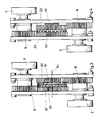
- Figure 1 is a front view, in elevation, with partial breaks, of a door part on which is mounted a security lock comprising a device with clutch and release mechanism according to a first particular embodiment of the 'invention.
- Figure 2 is a side view, partially broken, of this lock with its clutch mechanism and disengagement mechanism, according to this first particular embodiment.
- Figure 3 is a side view of a second embodiment of the device with clutch and release mechanism according to the invention, in the disengaged position.
- Figure 4 is a profile view similar to that of Figure 3 in which the device with clutch and release mechanism according to this second embodiment is in the engaged position.
- a declutching and clutching mechanism is mounted between these handles 2 and 3 and cooperates with control means 7 making it possible to bring this mechanism either into a disengaged state, or into a engaged state.
- the first handle 2 can cooperate directly with the bolt 1, that is to say by acting directly on the drive mechanism thereof arranged in the housing of the lock itself, while the second handle 3 cooperates with the bolt 1 via the clutch and disengage mechanism 6.
- the declutching and clutching mechanism 6 comprises a gear made up of three toothed wheels 8, 9 and 10.
- the first gear 8 cooperates with the first handle 2
- the second gear 3 cooperates with the second handle 3 and the third transmission gear 10 being mounted between these two gear 8 and 9.
- the transmission toothed wheel 10 is movable along its axis 5c, between a disengaged position, as shown in solid lines in FIG. 2, and a position engaged with the two cogwheels 8 and 9, as shown in phantom in Figure 2.
- the control means 7 are arranged so as to allow this third wheel 10 to be moved between its engaged position and its disengaged position.
- the toothed wheel 8 is wedged on a follower 11 receiving the square rod 12, on which is wedged the handle 2 and which rotates around the axis 5a.
- the toothed wheel 9 is wedged on a follower 13 receiving a square rod 14 on which the handle 3 is rigidly fixed and which rotates around the axis 5b.
- the transmission wheel 10 for its part, has a hub 15 which rotates freely around the axis 5c.
- the aforementioned control means 7 are formed essentially by an electromagnet 16 mounted coaxially with the wheel 10 and allowing, when the latter is excited by the passage of an electric current in its winding, to subject this wheel to a displacement according to its axis, as shown by arrow 17, against a helical spring 18, from its disengaged position to its engaged position.
- the spring 18 is mounted coaxially with the electromagnet 16 and the toothed wheel 10, so as to allow the latter to be pushed back into its disengaged position when the electromagnet is not excited.
- At least the hub 15 is made of a ferromagnetic material, more particularly of soft iron.
- the projecting part 15 of the hub of the toothed wheel 10 which can move in sliding manner in the central part of the winding of the electromagnet 7, has a cylindrical recess 19 in which can lodge the end of the spring 18 oriented towards the toothed wheel 10.
- the toothed wheel 10 is preferably mounted so as to remain constantly meshed with one of the other two toothed wheels 8 and 9 during its movement between its engaged position and its disengaged position.
- the toothed wheel 10 is mounted so as to remain constantly meshed with the toothed wheel 8.
- the plane of symmetry of the toothed wheel 8 perpendicular to the axis 5a of the latter is offset towards the handle 2 relative to the corresponding plane of symmetry of the toothed wheel 9.
- the teeth (21) of the gear wheels advantageously have a pointed appearance.
- FIGS. 3 and 4 differs essentially from that shown in FIGS. 1 and 2, by the fact that it comprises two transmission toothed wheels 10 ′ and 10 ⁇ in replacement of the transmission toothed wheel unique 10.
- These two transmission toothed wheels 10 ′ and 10 ⁇ are coaxial and rotate around a common axis (5c).
- the toothed wheel 10 ′ remains constantly engaged with the toothed wheel 8, while always remaining free relative to the toothed wheel 9, while the toothed wheel 10 ⁇ remains constantly meshed with the toothed wheel 9 while always remaining free relative to the gear 8.
- the wheel 10 ′ is movable along its axis 5c between a free position relative to the wheel 10 ⁇ and an immobilized position relative to the latter so as to be able to rotate together with the latter.
- the wheels 10 ′ and 10 ⁇ have, on their lateral faces opposite, a toothed crown 22 and 23 respectively, the teeth of which mesh, as shown in FIG. FIG. 4, these crowns being in the disengaged position in FIG. 3.
- the clutch that is to say the axial approximation of the wheels 10 ′ and 10 ⁇ can be done by the excitation of an electromagnet, not shown in Figures 3 and 4, mounted on one of these 10 ′ and 10 ⁇ wheels.
- a toothed wheel different from the transmission toothed wheel could form one which is movable along its axis to pass from the engaged position to the disengaged position and vice versa.
- the electromagnet can be excited, for example, using a code via a keyboard, not shown, located on the side of the handle 3.
- the electromagnet 7 attracts the axially movable toothed wheel, so that the door can be opened by turning the handle 3, provided that the lock is not closed by a key 20. In the latter case, the lock will remain blocked.
Abstract
Description
La présente invention est relative à un dispositif pour actionner une serrure de sécurité à pêne mobile manoeuvré par deux poignées, ces dernières étant agencées de part et d'autre d'une porte et tournant autour d'axes séparés sensiblement parallèles, entre une position de fermeture et une position d'ouverture, un mécanisme de débrayage et d'embrayage étant monté entre ces poignées, des moyens de commande comprenant un électro-aimant étant prévus permettant d'amener ce mécanisme soit dans un état débrayé, soit dans son état embrayé, la première poignée pouvant coopérer directement avec le pêne, la seconde poignée pouvant coopérer avec ce dernier par l'intermédiaire du mécanisme de débrayage et d'embrayage, le mécanisme de débrayage et d'embrayage comprenant un engrenage constitué d'au moins trois roues dentées, une première roue dentée coopérant avec ladite première poignée, une seconde roue dentée coopérant avec avec ladite seconde poignée et une troisième roue dentée de transmission montée entre ces première et seconde roues dentées, au moins une de ces roues dentées étant mobile, sensiblement suivant son axe entre une position embrayée avec les deux autres roues dentées et une position débrayée par rapport à au moins une de ces deux autres roues dentées, les moyens de commande étant agencés de manière à permettre de déplacer cette roue mobile entre sa position embrayée et sa position débrayée.The present invention relates to a device for actuating a movable bolt security lock operated by two handles, the latter being arranged on either side of a door and rotating around separate axes which are substantially parallel, between a position of closing and an open position, a disengagement and clutch mechanism being mounted between these handles, control means comprising an electromagnet being provided making it possible to bring this mechanism either in a disengaged state, or in its engaged state , the first handle being able to cooperate directly with the bolt, the second handle being able to cooperate with the latter by means of the declutching and clutching mechanism, the declutching and clutching mechanism comprising a gear made up of at least three wheels gears, a first gear wheel cooperating with said first handle, a second gear wheel cooperating with said second handle ée and a third transmission toothed wheel mounted between these first and second toothed wheels, at least one of these toothed wheels being movable, substantially along its axis between a position engaged with the other two toothed wheels and a position disengaged from at least one of these two other toothed wheels, the control means being arranged so as to allow this movable wheel to be moved between its engaged position and its disengaged position.
Un dispositif de ce genre est connu du document DE-A-3310822. Il s'agit notamment de serrures à pêne demitour pouvant se déplacer à l'encontre d'un ressort lors du pivotement d'une des poignées, entre une position de fermeture, dans laquelle le pêne est engagé dans une gâche prévue dans un chambranle, et une position d'ouverture, dans laquelle le pêne est retiré de la gâche à l'encontre de ce ressort.A device of this kind is known from document DE-A-3310822. These are in particular half-turn bolt locks which can move against a spring when one of the handles is pivoted, between a closed position, in which the bolt is engaged in a keeper provided in a frame, and an open position, in which the bolt is withdrawn from the strike against this spring.
Par l'expression "pêne mobile", il faut entendre en fait tout pêne pouvant se déplacer sans clé dans la serrure, c'est-à-dire par l'action d'une poignée ou d'un ressort, à la différence d'un pêne dormant qui nécessite généralement l'utilisation d'une clé pour l'amener d'une position à une autre.By the expression "movable bolt" is meant in fact any bolt which can move without a key in the lock, that is to say by the action of a handle or a spring, unlike a deadbolt which generally requires the use of a key to bring it from one position to another.
Par ailleurs, dans le présent texte, par "poignée pouvant coopérer directement avec le pêne", il y a lieu d'entendre une poignée qui permet de commander le pêne indépendamment du mécanisme de débrayage, éventuellement par l'intermédiaire d'un système de transmission, tel que par exemple un levier agissant directement à partir de la poignée sur le pêne. Lorsque la poignée commande simultanément plusieurs pênes se répartissant sur le chant d'une porte, comme par exemple dans certaines portes antiinfraction et/ou coupe-feu, ce système de transmission peut être formé par une série de tringles.Furthermore, in the present text, by "handle capable of cooperating directly with the bolt", it is understood to mean a handle which makes it possible to control the bolt independently of the declutching mechanism, possibly by means of a system of transmission, such as for example a lever acting directly from the handle on the bolt. When the handle simultaneously controls several bolts distributed over the edge of a door, as for example in certain burglar-resistant and / or fire-resistant doors, this transmission system can be formed by a series of rods.
La présente invention concerne donc un dispositif pouvant actionner aussi bien une serrure de sécurité à un pêne qu'à plusieurs pênes mobiles distancés et l'un de ses buts essentiels est de présenter un dispositif du type précité d'une construction extrêmement simple et fiable pouvant surtout être monté sur une serrure de hauteur relativement réduite et dont le déplacement du pêne nécessite une rotation des poignées autour d'un angle relativement important de l'ordre de 90°.The present invention therefore relates to a device which can actuate both a security lock with a bolt and several mobile bolts spaced apart and one of its essential aims is to present a device of the above type of an extremely simple and reliable construction which can especially be mounted on a lock of relatively reduced height and whose movement of the bolt requires a rotation of the handles around a relatively large angle of the order of 90 °.
Pour atteindre cet objectif l'invention prévoit un dispositif du genre précité qui est caractérisé en ce que l'électro-aimant est monté sensiblement coaxialement à la troisième roue dentée de telle façon que, lorsque ce dernier est excité par le passage d'un courant électrique dans son bobinage, cette troisième roue dentée puisse être soumise à un déplacement suivant son axe, à l'encontre d'un ressort, d'une des deux positions précitées à l'autre position, ce ressort étant agencé de manière à permettre de déplacer et de maintenir la troisième roue dentée dans sa position initiale lorsque l'électro-aimant n'est pas excité.To achieve this objective, the invention provides a device of the aforementioned type which is characterized in that the electromagnet is mounted substantially coaxially with the third toothed wheel so that when the latter is excited by the passage of a current electric in its winding, this third gear can be subjected to a displacement along its axis, against a spring, from one of the two aforementioned positions to the other position, this spring being arranged so as to allow move and maintain the third gear in its initial position when the electromagnet is not energized.
Suivant une forme de réalisation préférée de l'invention, lorsque l'électro-aimant est excité, celui-ci monté de manière à attirer la troisième roue dentée, qui présente au moins une partie ferro-magnétique, dans sa position embrayée à l'encontre du ressort précité, qui est un ressort hélicoïdal monté coaxialement à l'électro-aimant et à la troisième roue dentée, ce ressort permettant de repousser la troisième roue dentée dans sa position débrayée lorsque l'électro-aimant n'est pas excité.According to a preferred embodiment of the invention, when the electromagnet is energized, it mounted so as to attract the third toothed wheel, which has at least one ferromagnetic part, in its position engaged to the against the aforementioned spring, which is a helical spring mounted coaxially with the electromagnet and the third toothed wheel, this spring making it possible to push the third toothed wheel back into its disengaged position when the electromagnet is not excited.
Enfin, l'invention concerne une porte munie d'une telle serrure de sécurité.Finally, the invention relates to a door provided with such a security lock.
D'autres détails et particularités de l'invention ressortiront de la description donnée ci-après, à titre d'exemple non limitatif, de deux formes de réalisation particulières d'une serrure de sécurité muni d'un dispositif à mécanisme d'embrayage et de débrayage, suivant l'invention, avec référence aux dessins annexés.Other details and particularities of the invention will emerge from the description given below, by way of nonlimiting example, of two particular embodiments of a security lock provided with a device with a clutch mechanism and clutch, according to the invention, with reference to the accompanying drawings.
La figure 1 est une vue de face, en élévation, avec brisures partielles, d'une partie de porte sur laquelle est montée une serrure de sécurité comportant un dispositif à mécanisme d'embrayage et de débrayage suivant une première forme de réalisation particulière de l'invention.Figure 1 is a front view, in elevation, with partial breaks, of a door part on which is mounted a security lock comprising a device with clutch and release mechanism according to a first particular embodiment of the 'invention.
La figure 2 est une vue de profil, avec brisure partielle, de cette serrure avec son dispositif à mécanisme d'embrayage et de débrayage, suivant cette première forme de réalisation particulière.Figure 2 is a side view, partially broken, of this lock with its clutch mechanism and disengagement mechanism, according to this first particular embodiment.
La figure 3 est une vue de profil d'une deuxième forme de réalisation du dispositif à mécanisme d'embrayage et de débrayage suivant l'invention, dans la position débrayée.Figure 3 is a side view of a second embodiment of the device with clutch and release mechanism according to the invention, in the disengaged position.
La figure 4 est une vue de profil analogue à celle de la figure 3 dans laquelle le dispositif à mécanisme d'embrayage et de débrayage suivant cette deuxième forme de réalisation est dans la postion embrayée.Figure 4 is a profile view similar to that of Figure 3 in which the device with clutch and release mechanism according to this second embodiment is in the engaged position.
Dans les différentes figures, les mêmes chiffres de références se rapportent aux mêmes éléments.In the different figures, the same reference numbers refer to the same elements.
Etant donné que le mécanisme d'entraînement et de commande même de la serrure de sécurité, sur laquelle le dispositif d'embrayage et de débrayage suivant l'invention s'applique, peut être celui d'une serrure de sécurité connue en soi, ce mécanisme d'entraînement et de commande n'a pas été représenté en détail aux figures.Given that the drive and control mechanism itself of the safety lock, to which the clutch and disengage device according to the invention applies, may be that of a safety lock known per se, this drive and control mechanism has not been shown in detail in the figures.
Il suffit en fait qu'il s'agisse d'une serrure de sécurité à pêne mobile 1 manoeuvré par deux poignées 2 et 3 qui sont agencées de part et d'autre de la feuille de porte 4 et que tournent autour d'axes séparés sensiblement parallèles 5a, respectivement 5b, entre une position de fermeture, dans laquelle la gâche 1 fait saillie par rapport à la tranche 4′ du battant de porte 4, et une position d'ouverture, dans laquelle le pêne est donc rentré.It suffices in fact that it is a security lock with
Un mécanisme de débrayage et d'embrayage est monté entre ces poignées 2 et 3 et coopère avec des moyens de commande 7 permettant d'amener ce mécanisme soit dans un état débrayé, soit dans un état embrayé.A declutching and clutching mechanism is mounted between these
La première poignée 2 peut coopérer directement avec le pêne 1, c'est-à-dire en agissant directement sur le mécanisme d'entraînement de celui-ci agencé dans le boîtier de la serrure même, tandis que la seconde poignée 3 coopère avec le pêne 1 par l'intermédiaire du mécanisme d'embrayage et de débrayage 6.The
Suivant l'invention, dans la forme de réalisation montrée aux figures 1 et 2, le mécanisme de débrayage et d'embrayage 6 comprend un engrenage constitué de trois roues dentées 8, 9 et 10.According to the invention, in the embodiment shown in FIGS. 1 and 2, the declutching and
La première roue dentée 8 coopère avec la première poignée 2, la seconde roue dentée 3 coopérant avec la seconde poignée 3 et la troisième roue dentée de transmission 10 étant monté entre ces deux roues dentées 8 et 9.The
La roue dentée de transmission 10 est mobile suivant son axe 5c, entre une position débrayée, comme montré en traits pleins à la figure 2, et une position embrayée avec les deux roues dentées 8 et 9, comme montré en traits mixtes sur la figure 2.The transmission
Les moyens de commande 7 sont agencés de manière à permettre de déplacer cette troisième roue 10 entre sa position embrayée et sa position débrayée.The control means 7 are arranged so as to allow this
Plus particulièrement, dans cette forme de réalisation particulière, la roue dentée 8 est calée sur un fouillot 11 recevant la tige carrée 12, sur laquelle est calée la poignée 2 et qui tourne autour de l'axe 5a.More particularly, in this particular embodiment, the
La roue dentée 9 est calée sur un fouillot 13 recevant une tige carrée 14 sur laquelle est fixée rigidement la poignée 3 et qui tourne autour de l'axe 5b.The
La roue de transmission 10, de son côté, présente un moyeu 15 qui tourne librement autour de l'axe 5c.The
Les moyens de commande précités 7 sont formés essentiellement par un électro-aimant 16 monté coaxialement à la roue 10 et permettant, lorsque ce dernier est excité par le passage d'un courant électrique dans son bobinage, de soumettre cette roue à un déplacement suivant son axe, comme montré par la flèche 17, à l'encontre d'un ressort hélicoïdal 18, de sa position débrayée à sa position embrayée. Le ressort 18 est monté coaxialement à l'électro-aimant 16 et à la roue dentée 10, de manière à permettre de repousser cette dernière dans sa position débrayée lorsque l'électro-aimant n'est pas excité.The aforementioned control means 7 are formed essentially by an
Afin de permettre à l'électro-aimant d'attirer la roue dentée 10, au moins le moyeu 15 est constitué d'une matière ferro-magnétique, plus particulièrement de fer doux.In order to allow the electromagnet to attract the
De plus, toujours dans cette forme de réalisation spécifique, la partie saillante 15 du moyeu de la roue dentée 10 qui peut se déplacer à coulissement dans la partie centrale du bobinage de l'électro-aimant 7, présente un évidement cylindrique 19 dans laquelle peut se loger l'extrémité du ressort 18 orientée vers la roue dentée 10.In addition, still in this specific embodiment, the projecting
Par ailleurs, la roue dentée 10 est de préférence montée de manière à rester constamment engrenée avec une des deux autres roues dentées 8 et 9 lors de son déplacement entre sa position embrayée et sa position débrayée.Furthermore, the
Dans cette forme de réalisation particulière, la roue dentée 10 est montée de manière à rester constamment engrenée avec la roue dentée 8.In this particular embodiment, the
Ainsi, le plan de symmétrie de la roue dentée 8 perpendiculaire à l'axe 5a de cette dernière est décalé vers la poignée 2 par rapport au plan de symmétrie correspondant de la roue dentée 9.Thus, the plane of symmetry of the
Dans certain cas, afin de permettre d'engrener aisément la roue dentée 10 avec la roue dentée 9 lors du passage de la position débrayée à la position embrayée, les dents (21) des roues dentées présentent avantageusement une allure pointue.In certain cases, in order to allow the
La forme de réalisation illustrée par les figures 3 et 4 se distingue essentiellement par rapport à celle montrée aux figures 1 et 2, par le fait qu'elle comprend deux roues dentées de transmission 10′ et 10˝ en remplacement de la roue dentée de transmission unique 10.The embodiment illustrated in FIGS. 3 and 4 differs essentially from that shown in FIGS. 1 and 2, by the fact that it comprises two transmission
Ces deux roues dentées de transmission 10′ et 10˝ sont coaxiales et tournent autour d'un axe commun (5c). La roue dentée 10′ reste constamment engagée avec la roue dentée 8, tout en restant toujours libre par rapport à la roue dentée 9, tandis que la roue dentée 10˝ reste constamment engrenée avec la roue dentée 9 tout en restant toujours libre par rapport à la roue dentée 8.These two transmission
La roue 10′ est mobile suivant son axe 5c entre une position libre par rapport à la roue 10˝ et une position immobilisée par rapport à cette dernière de manière à pouvoir tourner ensemble avec celle-ci.The
A cet égard, dans la forme de réalisation particulière montrée aux figures 3 et 4, les roues 10′ et 10˝ présentent sur leurs faces latérales en regard une couronne dentée respectivement 22 et 23, dont les dent s'engrènent,comme montrée à la figure 4, ces couronnes étant dans la position débrayée à la figure 3.In this regard, in the particular embodiment shown in FIGS. 3 and 4, the
L'embrayage, c'est-à-dire le rapprochement axial des roues 10′ et 10˝ peut se faire par l'excitation d'un électro-aimant, non représenté aux figures 3 et 4, monté sur une de ces roues 10′ et 10˝.The clutch, that is to say the axial approximation of the
Il est bien entendu que l'invention n'est pas limitée à la forme de réalisation spécifique décrite ci-dessus et représentée dans les dessins, mais que d'autres variantes peuvent être envisagées sans sortir du cadre de la présente invention telle que définie par les revendications.It is understood that the invention is not limited to the specific embodiment described above and shown in the drawings, but that other variants can be envisaged without departing from the scope of the present invention as defined by the revendications.
C'est ainsi que d'autres moyens pourraient être envisagés pour permettre de déplacer la roue mobile suivant son axe entre sa position embrayée et sa postion débrayée.This is how other means could be envisaged to allow the moving wheel to be moved along its axis between its engaged position and its disengaged position.
Enfin, dans d'autres cas encore une roue dentée différente de la roue dentée de transmission pourrait former celle qui est mobile suivant son axe pour passer de la position embrayée à la position débrayée et inversément.Finally, in still other cases a toothed wheel different from the transmission toothed wheel could form one which is movable along its axis to pass from the engaged position to the disengaged position and vice versa.
L'excitation de l'électro-aimant peut être réalisé p.e. à l'aide d'un code via un clavier, non représenté, situé du côté de la poignée 3.The electromagnet can be excited, for example, using a code via a keyboard, not shown, located on the side of the
Ainsi, si le code exact est introduit, l'électro-aimant 7 attire la roue dentée mobile axialement, de sorte que l'on peut ouvrir la porte en tournant la poignée 3, ceci pour autant que la serrure ne soit pas fermée par une clé 20. Dans ce dernier cas, la serrure restera bloquée.Thus, if the exact code is entered, the
Claims (7)
- A device for actuating a safety lock having a spring bolt (1) controlled by a first and a second handle (2,3) provided on a first and a second side of a door (4), said first and second handle being able to rotate around substantially parallel separate axes (5a,5b) between a closed and an open position, an engaging and disengaging mechanism (6) being mounted between said first and second handles (2,3), said device being provided with control means (7) having a solenoid for bringing said mechanism either in a disengaging or in an engaging state, said first handle (2) being provided for directly cooperating with said bolt (1), said second handle (3) being able to cooperate with said bolt through said disengaging and engaging mechanism (7), said disengaging and engaging mechanism (7) comprises a gearing formed by at least three toothed wheels, a first toothed wheel (8) cooperating with said first handle (2), a second toothed wheel (9) cooperating with said second handle (3) and a third toothed transmission wheel (10) being mounted between said first and second toothed wheels (8,9) at least one of those toothed wheels (10) being movable, substantially according to its axis (5c) , between an engaged position with the two other toothed wheels (8,9) and a disengaged position with respect to at least one of those other toothed wheels (9), said control means (7) being provided for enabling the displacement of said movable wheel (10) between said engaged and disengaged position; characterized in that said solenoid (7) is mounted substantially coaxially to said third toothed wheel (10) and enabling, when said solenoid (7) is excited by an electric current passing through a winding thereof, to underly said third toothed wheel (10) to a displacement along its axis (5c) from one of the two positions to the other one and against a spring (18), said spring (18) being provided for enabling a displacement and maintaining of said third toothed wheel (10) in its original position when the solenoid (7) is not excited.
- A device as claimed in claim 4 characterized in that when said solenoid (79 is excited, it is mounted in order to attract said third toothed wheel (10), which presents at least a ferromagnetic part (15), in its engaged position against said spring (18), which is a helical spring mounted coaxially on said solenoid (7) and on said third toothed wheel (10), said spring (18) enables to pull back said third toothed wheel (10) in its disengaged position when said solenoid (7) is not excited.
- A device as claimed in claim 1, characterized in that said thoothed wheel (10) is mounted in such a manner as to remain constantly geared with one of said other wheels (8,9) when it is displaced between said engaged and disengaged position.
- A device as claimed in claim 3 characterized in that said third toothed wheel (10) is mounted in such a manner as to remain constantly geared with said first toothed wheel (8).
- A device as claimed in claim 3 or 4 characterized in that a symmetry plane of said first toothed wheel (8) perpendicular to its axis (5a) is shifted with respect to a corresponding symmetry plane of said second toothed wheel (9,), in such a manner that said third toothed wheel (10) always remain geared with one of said first or second wheel (8) in its engaged and disengaged position.
- A device as claimed in anyone of claims 1 to 5 characterized in that the tooths (21) of said toothed wheels (8,9,10) present a pointed aspect, in such a manner as to permit a easy gearing of said third toothed wheel (10) with the two other wheels (8,9), by a transmission from the disengaged to the engaged position.
- A device as claimed in claim 1, characterized in that said disengaging and engaging mechanism comprises a gearing formed by at least four toothed wheels, said first toothed wheel (8) cooperates with said first handle (2), said second toothed wheel (9) cooperates with said second handle (3), a third and a fourth toothed transmission wheel (10,10') being coaxially mounted and disposed between said first and second toothed wheels (8,9) and which can be immobile with repect to one another, said third toothed wheel (10) being mounted in such a manner as to remain constantly engaged with said first toothed wheel (8), said fourth toothed wheel (10'') being mounted in such a manner as to remain constantly engaged with said second toothed wheel (9), at least one of said third or fourth toothed wheel (10,10') being movable along its axis (5c) between an immobile position with respect to the other toothed wheel (10') or (10''), in such a manner as to be able to rotate together with that latter around its axis and thus to correspond with the engaged state, and a free position with respect to that latter, corresponding to said disengaged state.
Priority Applications (1)
| Application Number | Priority Date | Filing Date | Title |
|---|---|---|---|
| AT88202980T ATE81702T1 (en) | 1987-12-29 | 1988-12-21 | LOCK WITH COUPLING AND UNCOUPLING DEVICE. |
Applications Claiming Priority (2)
| Application Number | Priority Date | Filing Date | Title |
|---|---|---|---|
| BE8701496A BE1001398A6 (en) | 1987-12-29 | 1987-12-29 | Lock clutch device and clutch. |
| BE8701496 | 1987-12-29 |
Publications (2)
| Publication Number | Publication Date |
|---|---|
| EP0325813A1 EP0325813A1 (en) | 1989-08-02 |
| EP0325813B1 true EP0325813B1 (en) | 1992-10-21 |
Family
ID=3883035
Family Applications (1)
| Application Number | Title | Priority Date | Filing Date |
|---|---|---|---|
| EP88202980A Expired - Lifetime EP0325813B1 (en) | 1987-12-29 | 1988-12-21 | Lock with a clutch |
Country Status (5)
| Country | Link |
|---|---|
| EP (1) | EP0325813B1 (en) |
| AT (1) | ATE81702T1 (en) |
| BE (1) | BE1001398A6 (en) |
| DE (1) | DE3875470D1 (en) |
| PT (1) | PT89342B (en) |
Families Citing this family (6)
| Publication number | Priority date | Publication date | Assignee | Title |
|---|---|---|---|---|
| FR2674278B1 (en) * | 1991-03-21 | 1995-10-06 | Vachette Sa | CONTROL DEVICE FOR A LOCK AND LOCK EQUIPPED WITH SUCH A DEVICE. |
| GB2305965A (en) * | 1995-10-07 | 1997-04-23 | Taylor Lock | Electrically-operated spindle |
| DE19714612B4 (en) * | 1997-04-09 | 2007-11-08 | Insys Microelectronics Gmbh | Electromechanical lock |
| FI121681B (en) * | 2009-01-05 | 2011-02-28 | Megalock Oy | Lock accessory |
| FI20095694A (en) * | 2009-01-05 | 2010-07-06 | Megalock Oy | Wireless controllable electric lock |
| CN103470107B (en) * | 2013-09-22 | 2015-07-15 | 邓勇强 | Double-clutch device for high-safety electronic lock and electronic lock |
Family Cites Families (3)
| Publication number | Priority date | Publication date | Assignee | Title |
|---|---|---|---|---|
| FR2239894A5 (en) * | 1973-07-30 | 1975-02-28 | Bezault Sa | Offset mechanism for door handles - uses three intermeshing cogs so handle may be moved from door edge |
| US4073527A (en) * | 1977-01-12 | 1978-02-14 | Schlage Lock Company | Electrically controlled door lock |
| DE3310822C2 (en) * | 1982-05-13 | 1985-08-29 | Klaus Dr. 8022 Grünwald Meister | Locking device with cylinder and two-axis coupling device |
-
1987
- 1987-12-29 BE BE8701496A patent/BE1001398A6/en not_active IP Right Cessation
-
1988
- 1988-12-21 EP EP88202980A patent/EP0325813B1/en not_active Expired - Lifetime
- 1988-12-21 AT AT88202980T patent/ATE81702T1/en not_active IP Right Cessation
- 1988-12-21 DE DE8888202980T patent/DE3875470D1/en not_active Expired - Lifetime
- 1988-12-27 PT PT89342A patent/PT89342B/en not_active IP Right Cessation
Also Published As
| Publication number | Publication date |
|---|---|
| DE3875470D1 (en) | 1992-11-26 |
| BE1001398A6 (en) | 1989-10-24 |
| EP0325813A1 (en) | 1989-08-02 |
| PT89342A (en) | 1989-09-14 |
| PT89342B (en) | 1993-11-30 |
| ATE81702T1 (en) | 1992-11-15 |
Similar Documents
| Publication | Publication Date | Title |
|---|---|---|
| FR3060630B1 (en) | AFFLEURANT OPENING CONTROL WITH EJECTION AND MECHANICAL OR ELECTRICAL RETRACTION. | |
| EP0959206B1 (en) | Motor vehicle door lock with electrical locking | |
| FR2704265A1 (en) | System for the centralised locking of doors of motor vehicles | |
| CH378184A (en) | Operating mechanism for combination locks | |
| EP0325813B1 (en) | Lock with a clutch | |
| EP0153234A1 (en) | Coupling and decoupling device, especially for a mechanism for electrically securing a motor vehicle door lock | |
| FR2641312A1 (en) | MECHANISM FOR TILTING DOORS | |
| EP0924373A1 (en) | Espagnolette lock for a door, french window or similar | |
| EP0034966B1 (en) | Electric actuating mechanism for a low tension circuit breaker | |
| EP0270425B1 (en) | Lock with a rotor connected to the bolt by a set of pinions | |
| EP0709535A2 (en) | Disengageable coupling device for two coaxial axles associated with lock operating handles | |
| EP2708684B1 (en) | Method and a fitting for locking a window | |
| EP0748916B1 (en) | Actuator for a gate or other closure panel | |
| EP3808925B1 (en) | Lock for a door of a motor vehicle | |
| FR2816977A1 (en) | Electrically powered door lock has motor with screw and nut drive to slide actuating bolt | |
| EP0312654B1 (en) | Safety lock | |
| FR2610977A1 (en) | High-security lock actuated by a motor | |
| FR3117279A1 (en) | Chassis device for draw-out electrical switchgear and assembly comprising said chassis device and such a device | |
| EP0262262B1 (en) | Device for actuating a safety-lock and lock comprising such a device | |
| EP0029403B1 (en) | Espagnolette lock for a door, french window or the like | |
| EP0565803A1 (en) | Electrically or mechanically operated locking device with narrow profile | |
| FR3048252A1 (en) | LOCK ASSEMBLY WITH INDEPENDENT ACTUATION SLINGS | |
| FR2621348A1 (en) | ELECTRICAL CONDEMNATION DEVICE FOR FERRULE SUCH AS CREMONE OR CREMONE-LOCK | |
| EP4249710A1 (en) | Control device for an espagnolette locking system for a sliding wing | |
| FR2756320A1 (en) | Drive mechanism and end-of-course detector for motor driven roller blinds |
Legal Events
| Date | Code | Title | Description |
|---|---|---|---|
| PUAI | Public reference made under article 153(3) epc to a published international application that has entered the european phase |
Free format text: ORIGINAL CODE: 0009012 |
|
| AK | Designated contracting states |
Kind code of ref document: A1 Designated state(s): AT BE CH DE ES FR GB GR IT LI LU NL SE |
|
| 17P | Request for examination filed |
Effective date: 19900111 |
|
| 17Q | First examination report despatched |
Effective date: 19910426 |
|
| GRAA | (expected) grant |
Free format text: ORIGINAL CODE: 0009210 |
|
| AK | Designated contracting states |
Kind code of ref document: B1 Designated state(s): AT BE CH DE ES FR GB GR IT LI LU NL SE |
|
| PG25 | Lapsed in a contracting state [announced via postgrant information from national office to epo] |
Ref country code: IT Free format text: LAPSE BECAUSE OF FAILURE TO SUBMIT A TRANSLATION OF THE DESCRIPTION OR TO PAY THE FEE WITHIN THE PRESCRIBED TIME-LIMIT;WARNING: LAPSES OF ITALIAN PATENTS WITH EFFECTIVE DATE BEFORE 2007 MAY HAVE OCCURRED AT ANY TIME BEFORE 2007. THE CORRECT EFFECTIVE DATE MAY BE DIFFERENT FROM THE ONE RECORDED. Effective date: 19921021 Ref country code: DE Effective date: 19921021 Ref country code: ES Free format text: THE PATENT HAS BEEN ANNULLED BY A DECISION OF A NATIONAL AUTHORITY Effective date: 19921021 Ref country code: GR Free format text: LAPSE BECAUSE OF FAILURE TO SUBMIT A TRANSLATION OF THE DESCRIPTION OR TO PAY THE FEE WITHIN THE PRESCRIBED TIME-LIMIT Effective date: 19921021 Ref country code: SE Effective date: 19921021 Ref country code: NL Effective date: 19921021 Ref country code: AT Effective date: 19921021 |
|
| REF | Corresponds to: |
Ref document number: 81702 Country of ref document: AT Date of ref document: 19921115 Kind code of ref document: T |
|
| REF | Corresponds to: |
Ref document number: 3875470 Country of ref document: DE Date of ref document: 19921126 |
|
| PG25 | Lapsed in a contracting state [announced via postgrant information from national office to epo] |
Ref country code: LU Free format text: LAPSE BECAUSE OF NON-PAYMENT OF DUE FEES Effective date: 19921231 Ref country code: CH Effective date: 19921231 Ref country code: LI Effective date: 19921231 |
|
| NLV1 | Nl: lapsed or annulled due to failure to fulfill the requirements of art. 29p and 29m of the patents act | ||
| GBV | Gb: ep patent (uk) treated as always having been void in accordance with gb section 77(7)/1977 [no translation filed] |
Effective date: 19921021 |
|
| REG | Reference to a national code |
Ref country code: GB Ref legal event code: 777A |
|
| PLBE | No opposition filed within time limit |
Free format text: ORIGINAL CODE: 0009261 |
|
| STAA | Information on the status of an ep patent application or granted ep patent |
Free format text: STATUS: NO OPPOSITION FILED WITHIN TIME LIMIT |
|
| REG | Reference to a national code |
Ref country code: CH Ref legal event code: PL |
|
| REG | Reference to a national code |
Ref country code: GB Ref legal event code: 777A |
|
| GBT | Gb: translation of ep patent filed (gb section 77(6)(a)/1977) |
Effective date: 19930819 |
|
| 26N | No opposition filed | ||
| PGFP | Annual fee paid to national office [announced via postgrant information from national office to epo] |
Ref country code: GB Payment date: 19970130 Year of fee payment: 9 |
|
| PG25 | Lapsed in a contracting state [announced via postgrant information from national office to epo] |
Ref country code: GB Free format text: LAPSE BECAUSE OF NON-PAYMENT OF DUE FEES Effective date: 19971221 |
|
| GBPC | Gb: european patent ceased through non-payment of renewal fee |
Effective date: 19971221 |
|
| REG | Reference to a national code |
Ref country code: GB Ref legal event code: 728V |
|
| REG | Reference to a national code |
Ref country code: GB Ref legal event code: 7281 |
|
| BECA | Be: change of holder's address |
Owner name: *MULTIMET SAH49 BOULEVARD PRINCE-HENRI, LU-1724 LU Effective date: 20041129 |
|
| REG | Reference to a national code |
Ref country code: FR Ref legal event code: TP |
|
| PGFP | Annual fee paid to national office [announced via postgrant information from national office to epo] |
Ref country code: BE Payment date: 20071127 Year of fee payment: 20 |
|
| PGFP | Annual fee paid to national office [announced via postgrant information from national office to epo] |
Ref country code: FR Payment date: 20071228 Year of fee payment: 20 |
|
| BE20 | Be: patent expired |
Owner name: MULTIMET SAH Effective date: 20081221 |