EP0325381B1 - A control system for operating a spray dampening system - Google Patents
A control system for operating a spray dampening system Download PDFInfo
- Publication number
- EP0325381B1 EP0325381B1 EP19890300326 EP89300326A EP0325381B1 EP 0325381 B1 EP0325381 B1 EP 0325381B1 EP 19890300326 EP19890300326 EP 19890300326 EP 89300326 A EP89300326 A EP 89300326A EP 0325381 B1 EP0325381 B1 EP 0325381B1
- Authority
- EP
- European Patent Office
- Prior art keywords
- speed
- pulse sequence
- rectangular pulse
- spray
- value
- Prior art date
- Legal status (The legal status is an assumption and is not a legal conclusion. Google has not performed a legal analysis and makes no representation as to the accuracy of the status listed.)
- Expired - Lifetime
Links
- 239000007921 spray Substances 0.000 title claims description 101
- 238000001208 nuclear magnetic resonance pulse sequence Methods 0.000 claims description 74
- 239000012530 fluid Substances 0.000 claims description 40
- 238000007639 printing Methods 0.000 claims description 37
- 230000004044 response Effects 0.000 claims description 18
- 238000000034 method Methods 0.000 claims description 6
- 238000012545 processing Methods 0.000 claims description 3
- 239000007788 liquid Substances 0.000 description 9
- 230000000712 assembly Effects 0.000 description 6
- 238000000429 assembly Methods 0.000 description 6
- 230000007246 mechanism Effects 0.000 description 6
- 238000007789 sealing Methods 0.000 description 4
- 230000009977 dual effect Effects 0.000 description 3
- 230000006870 function Effects 0.000 description 3
- 238000009736 wetting Methods 0.000 description 3
- 238000004891 communication Methods 0.000 description 2
- 230000006835 compression Effects 0.000 description 2
- 238000007906 compression Methods 0.000 description 2
- 238000001035 drying Methods 0.000 description 2
- 239000000463 material Substances 0.000 description 2
- 238000005507 spraying Methods 0.000 description 2
- UONOETXJSWQNOL-UHFFFAOYSA-N tungsten carbide Chemical compound [W+]#[C-] UONOETXJSWQNOL-UHFFFAOYSA-N 0.000 description 2
- 230000005355 Hall effect Effects 0.000 description 1
- 238000007792 addition Methods 0.000 description 1
- 239000000654 additive Substances 0.000 description 1
- 230000008859 change Effects 0.000 description 1
- 238000004140 cleaning Methods 0.000 description 1
- 238000012217 deletion Methods 0.000 description 1
- 230000037430 deletion Effects 0.000 description 1
- 238000003780 insertion Methods 0.000 description 1
- 230000037431 insertion Effects 0.000 description 1
- 239000004973 liquid crystal related substance Substances 0.000 description 1
- 238000012423 maintenance Methods 0.000 description 1
- 238000004519 manufacturing process Methods 0.000 description 1
- 238000012986 modification Methods 0.000 description 1
- 230000004048 modification Effects 0.000 description 1
- 238000007645 offset printing Methods 0.000 description 1
- 238000005192 partition Methods 0.000 description 1
- 238000000053 physical method Methods 0.000 description 1
- 238000010926 purge Methods 0.000 description 1
- 239000012858 resilient material Substances 0.000 description 1
- 239000007787 solid Substances 0.000 description 1
- 238000003860 storage Methods 0.000 description 1
- 238000006467 substitution reaction Methods 0.000 description 1
- 230000001052 transient effect Effects 0.000 description 1
- XLYOFNOQVPJJNP-UHFFFAOYSA-N water Substances O XLYOFNOQVPJJNP-UHFFFAOYSA-N 0.000 description 1
Images




Classifications
-
- B—PERFORMING OPERATIONS; TRANSPORTING
- B41—PRINTING; LINING MACHINES; TYPEWRITERS; STAMPS
- B41F—PRINTING MACHINES OR PRESSES
- B41F33/00—Indicating, counting, warning, control or safety devices
-
- B—PERFORMING OPERATIONS; TRANSPORTING
- B41—PRINTING; LINING MACHINES; TYPEWRITERS; STAMPS
- B41F—PRINTING MACHINES OR PRESSES
- B41F7/00—Rotary lithographic machines
- B41F7/20—Details
- B41F7/24—Damping devices
- B41F7/30—Damping devices using spraying elements
Definitions
- the dampener mechanism comprises a housing 30 upon which are mounted a plurality of sprayer assemblies 32. Those sprayer assemblies 32 are connected in parallel with a fluid inlet conduit 34 for receiving pressurized wetting liquid by means of separate take-off lines 36 leading from the inlet conduit 34 to the respective nozzle assemblies 36.
- Each sprayer assembly 32 comprises a nozzle section 38 and a valve section 40.
- the nozzle section 38 comprises a generally cylindrical nozzle housing 42 (FIG. 7) which includes a transverse slot 44 at its front end.
- a nozzle element 46 mounted by press-fit within a center bore of the nozzle housing 42 is a nozzle element 46, preferably formed of hard, wear-resistant material such as tungsten carbide.
- Press-fit into a rear end of the center bore is a retaining ring 48, and press-fit into a center hole of the ring 48 is a valve seat 50.
- the valve seat is of generally hollow cylindrical shape and includes a tapered end 52.
- the nozzle element 46 includes a slit 54 in its front end, which slit communicates with a center passage 56 of the valve seat 50 through a center passage 58 in the nozzle element 46.
- valve stem 110 Removably mounted in a front hollow end of the plunger is a valve stem 110.
- the valve stem 110 includes a rear portion 112 mounted by friction-fit within the plunger 104, and a front portion 114 of enlarged cross-section which slides within a throughbore 116 of a body member 118.
- the body member includes external threading 120 on its rear end which is screwed into the internal threading 74 of the valve housing.
- the body member 118 includes an internal bushing 119 within which a front end of the valve stem 110 slides.
- the valve stem includes a plurality of longitudinal channels 121 in its outer periphery for conducting liquid forwardly past the bushing 119 (see FIG. 10).
- the cycle time t TOT is, of course, the sum of the ON time t ON and the OFF time t OFF .
- the amount of dampening fluid dispensed by the spray dampener preferably has a nonlinear relationship to press speed. At press speeds below a certain speed S0, spray dampener output may be inhibited. This situation normally would occur as the press was being brought up to printing speed.
- the dampening percentage i.e., the percentage of time during which the nozzles release dampening fluid, increases linearly with press speed at a first rate.
- the dampening percentage varies linearly with press speed at different rates.
- spray bar 440 may be provided with eight spray nozzles N1-N8 arranged in a linear array.
- Spray bar 440 is preferably adapted to supply dampening fluid for a multipage printing press.
- the spray bar 440 provides dampening fluid for a four page printing press.
- nozzles N1 and N2 primarily control dampening of page 1
- nozzles N3 and N4 primarily control dampening of page 2
- nozzles N5 and N6 primarily control dampening of page 3
- nozzles N7 and N8 primarily control dampening of page 4.
- the spray patterns from adjacent nozzles overlap slightly.
Landscapes
- Engineering & Computer Science (AREA)
- Mechanical Engineering (AREA)
- Rotary Presses (AREA)
- Spray Control Apparatus (AREA)
- Coating Apparatus (AREA)
- Nozzles (AREA)
Description
- The present invention relates to a method of and control system for operating a spray dampening system, especially of the type utilized in a pulsed spray dampener system.
- Various systems have been proposed in the past for applying a fluid to the rollers of printing presses. These fluids may be used, for example, for dampening or cleaning the rollers, or for preventing printing offset. One type system dampens the rollers by spraying a fluid most from nozzle assemblies positioned adjacent the rollers. Typically, a plurality of nozzle assemblies are aligned in a spray bar.
- A sprayer assembly which has heretofore been employed is described later in this text in detail in connection with FIGURES 11-13. Briefly, that sprayer assembly is characterized by a nozzle section and a valve having a plunger positioned at an appreciable distance behind the nozzle section. Pressurized fluid is supplied to the valve and is directed to a sump when the valve is closed and to the nozzle section when the valve is open. The plunger is reciprocated by a solenoid to produce a pulsating spray.
- When the front sealing face of the plunger becomes worn, it is necessary to disassemble the solenoid mechanism in order to replace the plunger. This is a time-consuming task which must periodically be performed on all of the nozzle assemblies. Moreover, the need to conduct fluid to a sump when the valve is closed results in wasted fluid which must be disposed of. On the other hand, it has been found that if the feature of conducting pressurized fluid to a sump is eliminated, there will occur, upon opening of the valve, an excessive pressurizing of residual fluid remaining in the passage between the nozzle element and the valve plunger which can result in an excessive amount of fluid being sprayed, as well as a dripping of fluid after the valve has been closed. However, by conducting the pressurized fluid to a sump, no pressure build-ups will occur.
- Therefore, it would be desirable to provide a sprayer assembly in which the sealing face can be replaced with minimal time and effort, no excessive pressure build-ups occur, and there is no need to dispose of unused liquid.
- U.S. Patent No. 4,469,024 to Schwartz et al relates to a pulsed spray dampener wherein the amount of fluid which is dispensed is controlled by a measured press speed. In the disclosed embodiment, a speed sensor generates a sinusoidal sensor signal having a frequency related to the press speed. A pulse width modulator receives the sinusoidal sensor signal and generates a square wave control signal wherein the pulse duration is maintained constant. The time between pulses in the square wave control signal is varied as a function of press speed. The control signal is converted to pneumatic pulses used operate air-actuated valves which supply fluid to the spray nozzles.
- Another spray dampener system is disclosed in U.S. Patent No 4,649,818 to Switall et al. A speed sensor provides a sensor signal to a master controller which, on the basis of the sensor signal value, selects one of a plurality of oscillating electrical signals having discrete frequencies. The selected frequency signal is supplied to a monostable which produces a fixed-length pulse in response to the leading edge of each cycle of the frequency signal. The monostable pulses are then used to operate spray nozzle solenoids. The width of the monostable pulse may be adjusted manually.
- U.S. Patent No. 3,926,115 to Alsop discloses a spray dampening apparatus wherein the fluid output may be temporarily varied by partial or complete interruption of the spray. A solid obstructor may be placed in the spray path or a deflecting air blast may be used to vary the spray output. In the spray dampener disclosed in U.S. Patent No. 3,924,531 to Klinger, the output spray may be controlled by varying the position of various mechanical members.
- All of the known spray dampeners have had several drawbacks. For example, pulsed spray dampeners often encounter difficulties which lead to poor spray patterns and the like. In a system wherein the amount of dampening fluid is varied by changing the "ON" time of the spray nozzles, control of the dampening fluid output during low speed press operation is restricted by physical limitations in the spray nozzles, valves, and the like. Additionally, in systems wherein the "OFF" time of the spray nozzles is controlled, the controller is limited by the possibility of drying when there are long periods of time between spray pulses. Systems using a physical technique to vary spray output encounter difficulties in obtaining a proper spray pattern. Accordingly, there exists a need for a spray dampening system which overcomes the difficulties confronted in earlier spray dampening systems.
- It would be desirable to provide a spray dampening system which easily and effectively adjusts to changes in operating parameters.
- It would be further desirable to provide a spray dampening system having an improved spray pattern.
- It would also be desirable to provide an improved pulse spray dampening system for wetting a printing press roller wherein the amount of dampening fluid sprayed on the roller is varied in accordance with the speed of the printing press and a programmed dampening curve.
- The present invention provides a control system for operating a spray dampening system having a plurality of spray nozzles for supplying dampening fluid to a roller of a printing press, comprising means for obtaining a speed signal representative of a printing speed of said printing press, means for producing rectangular pulse sequences, and means for driving said nozzles in response to said rectangular pulse sequences; characterised in that said pulse sequence producing means is adapted to produce rectangular pulses of fixed duration and the time period between adjacent pulses is of varied duration in response to said speed signal when the value of said speed signal is below a first speed value and said pulse sequence producing means is adapted to produce rectangular pulses of varied duration and the time period between adjacent pulses is of fixed duration when the value of said speed signal is above said first speed value.
- The present invention also provides a method for controlling the operation of a spray dampening system having a plurality of solenoid-operated spray nozzles for supplying dampening fluid to a roller of a printing press, comprising the steps of obtaining a signal representative of a printing speed of said printing press, generating a rectangular pulse sequence, and driving said solenoids in response to said rectangular pulse sequence, characterised in that when said speed of said printing press is below a first speed value each rectangular pulse in said rectangular pulse sequence has a fixed duration and the time period between adjacent pulses is varied as a function of said speed signal, and when the speed of said printing press is above said first speed value the period between adjacent pulses in said rectangular pulse sequence is fixed and the duration of pulses is varied as a function of said speed signal.
- In accordance with the present invention, a spray dampener control system includes means for sensing the printing press speed. In response to the sensed press speed, a rectangular pulse sequence is generated. When the sensed press speed is below a particular value, each pulse in the rectangular pulse sequence has a fixed duration and the time period between adjacent pulses is varied in response to the press speed. When the press speed is above the partiuclar value, the time period between adjacent pulses is fixed and the duration of the pulses is varied in response to the sensed speed. Spray nozzles are driven in response to the rectangular pulse sequence.
- Certain embodiments of the invention will now be described, by way of example only, with reference to the accompanying drawings, wherein:
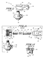
- FIGURE 1 is a perspective view of a spray mechanism, with portions of a printing mechanism depicted in phantom;
- FIGURE 2 is a side elevational view of a sprayer assembly;
- FIGURE 3 is a view similar to FIG, 2 displaced ninety degrees therefrom;
- FIGURE 4 is a rear end view of the sprayer assembly, with a solenoid casing thereof depicted in phantom lines;
- FIGURE 5 is a front end view of the sprayer assembly;
- FIGURE 6 is an exploded longitudinal sectional view of the sprayer assembly;
- FIGURE 7 is a fragmentary view of a nozzle section being sealingly engaged by a valve stem, with portions of the nozzle section being broken away;
- FIGURE 8 is a fragmentary longitudinal sectional view taken through the sprayer assembly when the nozzle section is closed by the valve stem;
- FIGURE 9 is a fragmentary exploded longitudinal sectional view taken through a valve section of the sprayer assembly depicting the valve stem being removed from the plunger;
- FIGURE 10 is a view similar to FIG. 8 with the valve stem in a retracted position to emit fluid flow to the nozzle;
- FIGURE 11 is a side elevational view of a prior art sprayer assembly;
- FIGURE 12 is an exploded view of the prior art sprayer assembly with portions thereof in longitudinal section;
- FIGURE 13 is a side elevational view, with portions broken away, of a prior art nozzle section;
- FIGURE 14 illustrates a rectangular pulse sequence used for actuating a spray nozzle solenoid;
- FIGURE 15 illustrates a dampening curve for correlating press speed to spray nozzle operation parameters;
- FIGURE 16 is a schematic drawing of one embodiment of a spray dampener control system in accordance with the present invention; and
- FIGURE 17 illustrates the relationships between spray nozzles, control channels, and printed pages in accordance with one feature of the present invention.
- Depicted in FIG. 1 is a portion of an
offset printing apparatus 10 comprising aplate cylinder roll 12, a water-form roll 14, adampening roll 16, and aspray dampener mechanism 18.
Thespray dampener mechanism 18 emits a pulsating spray of wetting liquid, such as water which may contain certain additives, the liquid being sprayed onto the dampener roll and from there transferred to the water-form roll. - The dampener mechanism comprises a
housing 30 upon which are mounted a plurality ofsprayer assemblies 32. Thosesprayer assemblies 32 are connected in parallel with afluid inlet conduit 34 for receiving pressurized wetting liquid by means of separate take-off lines 36 leading from theinlet conduit 34 to therespective nozzle assemblies 36. - Each
sprayer assembly 32 comprises anozzle section 38 and avalve section 40. Thenozzle section 38 comprises a generally cylindrical nozzle housing 42 (FIG. 7) which includes atransverse slot 44 at its front end. Mounted by press-fit within a center bore of thenozzle housing 42 is anozzle element 46, preferably formed of hard, wear-resistant material such as tungsten carbide. Press-fit into a rear end of the center bore is a retainingring 48, and press-fit into a center hole of thering 48 is avalve seat 50. The valve seat is of generally hollow cylindrical shape and includes atapered end 52. Thenozzle element 46 includes aslit 54 in its front end, which slit communicates with acenter passage 56 of thevalve seat 50 through acenter passage 58 in thenozzle element 46. - The
nozzle housing 42 is removably disposed in the front end of athroughbore 59 formed in a cap 60 (FIG. 6) of the type described in U.S. Patent No. 4,527,745 to Butterfield et al. Thecap 60 includesslots 62 in its outer wall for reasons to be explained hereinafter. - The valve section 40 (FIG. 6) comprises a
valve housing 70 which includes a through-bore 72, a front end of which containing aninternal thread 74. A liquid, such as a dampening solution, is supplied to thevalve housing 70 by means of aport 71 which may be threaded to receive a correspondingly threaded conduit. Removably attached to a rear end of the valve housing is ahollow post 76. Thepost 76 includes anenlarged flange 78 at its front end which fits into acounterbore 80 located at a rear end of thethroughbore 72. Aplate 82 has acentral opening 84 through which thepost 76 passes, theplate 82 being attached to therear side 86 of thevalve housing 70 by means ofscrews 88. Aresilient seal ring 90 is disposed between theplate 82 and theflange 78 to engage a flaredrear end 92 of thecounterbore 80 in order to create a fluid seal therewith. - Mounted on a rear end of the
post 76 is a conventional plug-in typesolenoid coil casing 96. That casing includes abore 98 through which thepost 76 extends. An annularexternal groove 100 is formed at the rear end of thepost 76 to receive a retaining ring (not shown) or the like for retaining thecasing 96 on the post. A spring (not shown) may be disposed between such retaining ring and arear surface 97 of the casing to bias the casing against theplate 82. The spring would be yieldable to permit the casing to be displaced slightly away from theplate 82 in order to be rotated about the axis of thepost 76 so that the three plug-inprongs 102 could be repositioned. - The
post 76 has a hollow front end into which avalve plunger 104 is slidably disposed so as to be positioned within thesolenoid coil casing 96. The plunger is adapted to be displaced rearwardly (i.e., upwardly as viewed in FIG. 6) in response to energization of the solenoid coil containing within thecasing 96. Acoil compression spring 106 surrounds theplunger 104 and acts between theflange 78 and aflange 108 situated at a front end of theplunger 104. Theflange 108 may be formed by a split retaining ring for example. Thus, when the plunger is retracted rearwardly by the solenoid coil, thespring 106 is compressed. - Removably mounted in a front hollow end of the plunger is a
valve stem 110. Thevalve stem 110 includes arear portion 112 mounted by friction-fit within theplunger 104, and afront portion 114 of enlarged cross-section which slides within athroughbore 116 of abody member 118. The body member includesexternal threading 120 on its rear end which is screwed into the internal threading 74 of the valve housing. Thebody member 118 includes aninternal bushing 119 within which a front end of thevalve stem 110 slides. The valve stem includes a plurality oflongitudinal channels 121 in its outer periphery for conducting liquid forwardly past the bushing 119 (see FIG. 10). - Projecting from the front end of the
stem 110 is adisc 122 formed on a resilient material. Thedisc 122 is of larger diameter than the rear end of thepassage 56 formed in thevalve seat 50 and is adapted to bear sealingly thereagainst under the bias of thespring 106. It will be appreciated that thepassages stem 114, theplunger 104, and thepost 76 are aligned along a common longitudinal axis. - The
stem 110 is no longer in cross-section than thethroughbore 116 of thebody 118, whereby thestem 114 can be pulled out of theplunger 104 and completely out of thesprayer assembly 32 in a forward direction after thecap 60 andnozzle section 38 have been removed therefrom. - Instead of being mounted by friction-fit, the stem could be attached to the plunger by other quick-release connections such as a threaded connection.
- Attachment and removal of the
nozzle section 38 is effected by thecap 60 in a conventional manner. That is, theslots 62 in the cap are arranged to receive radially projectinglugs 124 formed on the outer wall of thebody 118. The side walls of theslots 62 includecam portions 126 which serve to draw the cap toward thebody 118 in response to relative rotation therebetween. This causes thefront wall 128 to be forced longitudinally against anelastic seal ring 130 positioned between thefront wall 128 and arear wall 132 of thenozzle housing 42. Counter-rotation of the cap is yieldably resisted by thus-compressedring 130. Thering 130 also creates a fluid seal once it has been compressed in that fashion. - IN OPERATION, pressurized liquid is introduced to the sprayer assembly through the
port 71. If the solenoid is de-energized, i.e., in a non-spraying mode, the valve stem is biased against thevalve seat 50 to close the nozzle element. Once the solenoid has been actuated, the plunger and stem are retracted, thereby unblocking the valve seat. Pressurized liquid is immediately ejected through thevalve outlet 54 and onto the roll. After thesealing disc 122 has become worn, removal thereof is achieved by simply unscrewing thebody member 118 and pulling thestem 110 axially from the plunger. Insertion of a new stem is achieved by reversing those steps. - This nozzle assembly offers significant advantages over a nozzle assembly previously employed in spray dampeners. Such a prior
art nozzle assembly 236, depicted in FIGS. 11-13, comprises anozzle section 238 and avalve section 240. Thenozzle section 238 comprises a generallycylindrical nozzle housing 242 which includes atransverse slot 244 at its front end. Mounted by press-fit within a center bore of thenozzle housing 242 is anozzle element 246, preferably formed of a hard, wear-resistant material such as tungsten carbide. Press-fit into a rear end of the center bore is a retainingring 248. Thenozzle element 246 includes aslit 254 in its front end, which slit communicates with acenter passage 258 in thenozzle element 246. Thenozzle housing 238 if removably disposed in the front end of a throughbore formed in a cap 260 (FIG. 12) of the type described in U.S. Patent No. 4,527,745 to Butterfield et al. Thecap 260 includesslots 262 in its outer wall for reasons to be explained hereinafter. - The
valve section 240 comprises avalve housing 270 which includes first and second threaded bores 271, 272 separated by apartition 273. Thebores passage 258 in thenozzle housing 242. Disposed in thevalve housing 270 perpendicularly to thebores third bore 274. Thatthird bore 274 communicates with the first andsecond bores second passages hollow post 276. Thepost 276 includes anenlarged flange 278 at its front end which fits into acounterbore 280 at a rear end of thethird bore 274. Aplate 282 has acentral opening 284 through which thepost 276 passes, theplate 282 being attached to therear side 286 of thevalve housing 270 by means ofscrews 288. Aresilient seal ring 290 is disposed between theplate 282 and theflange 278 to engage a flaredrear end 292 of thecounterbore 280 in order to create a fluid seal therewith. - Mounted on a rear end of the
post 276 is a conventional plug-in typesolenoid coil casing 296. That casing includes abore 298 through which thepost 276 extends. An annularexternal groove 300 is formed at the rear end of thepost 276 to receive a retaining ring (not shown) or the like for retaining thecasing 296 on the post. A spring (not shown) may be disposed between such retaining ring and therear side 297 of the casing to bias the casing against theplate 282. Such spring would be yieldable to permit the casing to be displaced slightly away from theplate 282 in order to be rotated about the axis of thepost 276 so that the three plug-inprongs 302 could be repositioned. - The
post 276 has a hollow front end into which avalve plunger 304 is slidably disposed so as to be positioned within thesolenoid coil casing 296. The plunger is adapted to be displaced rearwardly (i.e., to the right in FIG. 12) in response to energization of the solenoid coil contained within thecasing 296. Acoil compression spring 306 surrounds theplunger 304 and acts against theflange 278 and aflange 308 situated at a front end of theplunger 304. Theflange 308 may be formed by a split retaining ring for example. Thus, when the plunger is retracted rearwardly by the solenoid coil, thespring 308 is compressed to bias the plunger forwardly. - Disposed in a front end of the
plunger 304 is anelastic sealing member 310 which is adapted to bear against atapered seat 312 surrounding thepassage 275A under the bias of thespring 306 whenever the solenoid coil is not energized. In so doing, thepassage 275A will be closed, while thepassage 275B will remain open. - The
plunger 304 includes at least onelongitudinal channel 314 which is adapted to conduct a flow of fluid from thepassage 275B to the rear end of thehollow post 276. Such fluid would flow around an outer edge of theflange 308, though thechannel 314 and through a small hole (not shown) at the rear of thepost 276 and from there to a suitable conduit (not shown) connected to the rear end of thepost 276. - Threadedly attached to the
first bore 271 is ahollow body member 318 on which thenozzle housing 242 is to be mounted by means of thecap 260. In that regard, theslots 262 in the cap are arranged to receive radially projectinglugs 324 formed on the outer wall of thebody 318. The side walls of theslots 262 includecam portions 326 which serve to draw the cap toward thebody 318 in response to relative rotation therebetween. This causes a front wall of thebody member 318 to be forced longitudinally against an electric seal ring (not shown) positioned between the front wall and a rear wall of thenozzle housing 242. - In operation of the prior art apparatus disclosed in connection with FIGS. 11-13, pressurized fluid is delivered to the
second bore 272 and flows through thepassage 275B. If the solenoid is not energized, thevalve plunger 304 closes thepassage 275A, so that the fluid travels through thechannel 314 and out the rear end of thepost 276 to a suitable sump. If the valve is energized, causing theplunger 304 to be retracted, thepassage 275A is opened, enabling fluid to flow therethrough and from there to the nozzle element. When the plunger is retracted, a seal at the wall 330 of the plunger engages the small hole (not shown) at a rear end of the plunger to close the flow to the sump. - It will be appreciated that this sprayer assembly enables a worn valve stem, to be replaced by merely unscrewing the
body member 118 and pulling forwardly on thestem 110 with a force sufficiently strong to overcome the resistance of the friction-fit of thestem portion 112 within theplunger 104. A new stem can then be inserted by being pushed into the plunger. Therefore, no appreciable disassembly of the valve assembly is required. - Furthermore, by providing a push-in, friction-
fit valve seat 50 for the rear end of the nozzle element, a conventional prior art nozzle section can be converted into a nozzle section as described. Such an arrangement enables fluid flow to be terminated directly at the rear side of the nozzle section. The short distance between the valve and the spray slit 54 avoids the occurrence of pressure surges and dripping, and avoids the need to divert unused pressurized fluid to a sump when the valve is closed. Hence, there is no need to dispose of large amounts of unused liquid. - Referring now to Fig. 14, a
signal 402 includes a sequence of rectangular pulses P and may be used for controlling actuation of the spray nozzle solenoids. Briefly, when thesignal 402 is in a "HIGH" or "ON" state, current is supplied to actuate a spray nozzle solenoid. The solenoid, and thus the spray nozzle, is de-actuated when thesignal 402 is in a "LOW" or "OFF" state. The duty cycle of the pulse sequence is determined by the width of a pulse P relative to the cycle time. In other words, the duty cycle D may be determined by taking the ratio of the ON time tON and the cycle time tTOT. The cycle time tTOT is, of course, the sum of the ON time tON and the OFF time tOFF. Thus, the duty cycle D may be defined at

- In order to adjust the spray output of the spray dampener, the duty cycle of the
signal 402 may be varied. a higher duty cycle would increase the spray output from the dampener. For example, a duty cycle of 1 would mean that thesignal 402 stayed in the ON position at all times and, thus, the spray nozzles would likewise remain ON at all times. The spray nozzles would remain in an OFF state for a duty cycle of 0. In theparticular signal 402 illustrated in Fig. 14, the pulse width tON is roughly one-third of the total cycle time tTOT. Hence, the duty cycle for theillustrative signal 402 in Fig. 14 would be approximately 0.33, and a spray nozzle controlled by the signal would be ON roughly 33.3% of operating time. - The duty cycle may be varied by changing one or both of the pulse width tON on the time tOFF between adjacent pulses of the pulse sequence defined by the
signal 402. In a typical spray dampener, however, system limitations often prevent proper operation of the spray dampener beyond particular operating parameters. For instance, in systems which vary the duty cycle by varying the width of a pulse, valve and nozzle limitations prevent proper operation for pulse widths below a certain value. Thus, systems which vary ON time often suffer from poor spray patterns during periods in which spray output is low. Similarly, systems which vary the duty cycle by adjusting OFF time confront problems associated with roller drying when relatively long periods of time elapse between spray pulses, particularly during high speed press operation. The present invention, however, overcomes these difficulties. - Referring to the dampening curve of Fig. 15, the amount of dampening fluid dispensed by the spray dampener preferably has a nonlinear relationship to press speed. At press speeds below a certain speed S₀, spray dampener output may be inhibited. This situation normally would occur as the press was being brought up to printing speed. As illustrated with dampening
curve 404, between speed S₀ and speed S₁, the dampening percentage, i.e., the percentage of time during which the nozzles release dampening fluid, increases linearly with press speed at a first rate. Likewise, between press speeds S₁ and S₂, between press speeds S₂ and S₃, and above speed S₃, the dampening percentage varies linearly with press speed at different rates. If desired, the dampening curve may include a purge signal which would output when the printing press is initially brought to speed s₀. The speeds at which the dampeningcurve 404 encounters a change in slope, and the particular slopes for the individual segments of the dampening curve will depend on the printing press in which the spray dampening system is used. - In accordance with one feature of the present invention, when the press speed is below speed S₂, the pulse width tON of nozzle control pulses P is set at a predetermined value e.g., 20 microseconds, which is sufficiently long to ensure a proper spray pattern. The dampening percentage may then be varied by adjusting the time period between adjacent pulses in the pulse sequence. When the press speed is above speed S₂, the time period between adjacent pulses is set at a predetermined value, e.g., 400 microseconds, which ensures that the printing press rollers will not dry excessively between pulses of spray during high speed press operation. The dampening percentage is then varied by adjusting the pulse width of the pulses P. In this way, the present invention obtains proper spray patterns and effective operation throughout a broad range of operating conditions.
- In another embodiment of the present invention, the pulse width between speeds S₀ and S₁, may be set at a first value, for example 20 microseconds, and the pulse width between speeds S₁ and S₂, when dampening requirements are higher, may be set at a higher second value such as 30 microseconds. Similarly, the time period between adjacent pulses of the pulse sequence for press speeds between speeds S₂ and S₃ may be set at one value, for example, 500 microseconds, and at another value such as 400 microseconds for press speeds above speed S₃. Thus, finer spray control is provided by adding additional set points along the dampening
curve 404. Of course, if desired even more set points could be sprovided on the dampening curve to permit even finer spray control. - Turning now to Fig. 16, a control system in accordance with the present invention includes a
main controller 406 including a central processing unit (CPU) 408, asystem memory 410, and an input/output (I/O)device 412. Additionally, a display device (not shown) such as a liquid crystal display, a light emitting diode (LED) display, or a cathode ray tube (CRT) may be provided to permit information concerning operating parameters and the like to be conveyed to a user. Thesystem memory 410 preferably includes a non-volatile memory portion for storing one or more dampening curves. - Dampening curves may be preprogrammed into the
system memory 410 or, preferably, the dampening curves may be downloaded from a computer or from a terminal device. For this purpose, aserial communications line 414 is provided to permit thecontroller 406 to communicate with a computer. Additionally, aterminal device 416 may communicate with thecontroller 406 through acommunication line 418. Thus, the characteristics of the dampening curve, which will usually vary between presses, may be tailored to the particular application in which the spray dampener is used. - In operation, if the dampening curve information is stored in a computer, this information may be downloaded to the
controller 406 through an appropriate serial interface, such as astandard RS 422 interface. This information may be supplied toCPU 408 for storage in thesystem memory 410. Preferably, for this purpose, thesystem memory 410 includes a programmable read-only memory device (PROM). Alternatively, the dampening curve information may be supplied to theCPU 408 from aterminal device 416. Thus, if desired a user can directly store an appropriate dampening curve in thesystem memory 410. - The
CPU 408 is adapted to receive a press speed indication signal on aninput line 420. The press speed indication signal may be obtained from a standard tachometer generator, Hall effect proximity sensor or other appropriate sensor. Additionally, in modern printing presses which include a printing computer, a press speed indication signal might already be available in the press computer. In this case, the press speed indication signal may be obtained directly from the printing computer. - The
CPU 408, in response to the speed indication signal, retrieves a record from thesystem memory 410 which contains information relating to the parameters of a spray nozzle actuation control signal. For instance, the speed indication signal might be converted into a memory address value. The contents stored in thesystem memory 410 at this address might then provide information indicating a duty cycle value for the spray nozzle actuation control signal. Based upon the stored duty cycle value and the speed indication signal, the parameters of the spray nozzle actuation signal may be calculated by theCPU 408. - For example, referring again to Fig. 15, if a speed-indication signal indicating a speed S₄ is obtained by the
main controller 406, a record stored insystem memory 410 in the appropriate memory location would including a duty cycle value 0.15 corresponding to 15% dampening. Since speed S₄ is lower than speed S₂, the pulse width tON is set at a fixed value such as 20 microseconds. As discussed above, the duty cycle D may be expressed as


- The pulse sequence parameters may similarly be calculated when the press speed value obtained by the
main controller 406 is greater than speed S₂. For example, for press speed S₅, the appropriate memory location insystem memory 410 would contain a record including a duty cycle value 0.22. Using a fixed time period of 400 microseconds between pulses, the pulse width value tON may be determined by solving the expression

- When a press speed value corresponds to speed S₂, i.e., the speed value at which the pulse sequence changes from using a fixed pulse width to using a fixed time period between adjacent pulses, the
main controller 406 may calculate either the pulse width tON or the time period tOFF. Turning back to Fig. 16, once theCPU 408 has determined the parameters of the spray nozzle actuating pulse sequence, the I/O unit 412 is controlled to output pulse sequence to the spray bar. In a preferred manner of forming the pulse sequence from the pulse parameters, theCPU 408 utilizes count values corresponding to the pulse width and the time period between pulses. If the pulse width count value is designated CON and the count value corresponding to the time period between pulses is designed COFF, theCPU 408 may generate a rectangular pulse sequence by providing a HIGH output signal for CON clock cycles and a LOW output signal for COFF clock cycles. Count values CON and COFF may themselves be stored insystem memory 410 for retrieval by theCPU 408 in response to the press speed indication signal. - Preferably the
CPU 408 produces pulse sequences one through six which are output by I/O unit 412 on first throughsixth output lines Output lines dual channel optocoupler 434. Similarly,output lines dual channel optocoupler 436, andoutput lines dual channel optocoupler 438. The optocouplers serve to help isolate themain controller 406 from possible damage caused by transient surges and the like. -
Output line 422, after passing throughoptocoupler 434, controls the operation of a power transistor TR1. Similarly,output line 424 controls the operation of power transistor TR2;output line 426 controls the operation of power transistor TR3;output line 428 controls the operation of power transistor TR4;output line 430 controls the operation of power transistor TR5; andoutput line 432 controls the operation of power transistor TR6. Thus, the pulse sequences appearing on output lines 422-432 determine the operating states of power transistors TR1-TR6, respectively. In turn, the operating states of transistors TR1-TR6 determine the signals appearing on control channels 1-6, respectively. - Referring to FIG. 17,
spray bar 440 may be provided with eight spray nozzles N1-N8 arranged in a linear array.Spray bar 440 is preferably adapted to supply dampening fluid for a multipage printing press. Typically, for example, thespray bar 440 provides dampening fluid for a four page printing press. In such a case, nozzles N1 and N2 primarily control dampening ofpage 1, nozzles N3 and N4 primarily control dampening ofpage 2, nozzles N5 and N6 primarily control dampening ofpage 3, and nozzles N7 and N8 primarily control dampening ofpage 4. Of course, the spray patterns from adjacent nozzles overlap slightly. - Since end nozzles N1 and N8 are situated at the outermost portions of the linear array of nozzles, there is no dampening contribution from overlapping spray from an adjacent outer nozzle. Thus, the portions of the dampening roller adjacent the outer portions of
pages - According to one feature of the present invention, this shortcoming of prior spray dampening systems has been overcome. As indicated in FIG. 17, nozzle N1 is controlled by
channel 1; nozzle N2 is controlled bychannel 2; nozzles N3 and N4 are controlled bychannel 3; nozzles N5 and N6 are controlled bychannel 4; nozzle N7 is controlled bychannel 5; and nozzle N8 is controlled bychannel 6. In order to compensate for increased heat and reduced dampening at the outer spray nozzles, the duty cycle of the pulse sequences oncontrol channels control channel 1 may be slightly higher than the duty cycle of the pulse sequence oncontrol channel 2. Similarly, the duty cycle of the pulse sequence oncontrol channel 6 may be slightly higher than the duty cycle of the pulse sequence oncontrol channel 5. Preferably the duty cycle of the pulse sequences oncontrol channels control channels control channels control channels - Since nozzles N1 and N8 each have a dedicated control channel, the different duty cycles may be accommodated. The
CPU 408 may be programmed to calculate the modified duty cycle for nozzles N1 and N8 and adjust the pulse sequences onoutput lines - Typically, in a multipage printing operation, the printing parameters will vary from page to page. These variances in printing parameters may result in one page requiring additional (or less) dampening fluid. Accordingly, each page is provided with a separate control channel. As illustrated in FIG. 17, nozzles N3 and N4 (page 2) are operated by
channel 3. Nozzles N5 and N6 (page 3) are controlled bychannel 4. Of course, since outer nozzles N1 and N8 have dedicated control channels, nozzles N2 and N7 also have individual control channels CH2 and CH5, respectively. Again, however, it is noted that the duty cycle of the pulse sequence onchannel 1 preferably is functionally related to the duty cycle of the pulse sequence onchannel 2, and the duty cycle of the pulse sequence onchannel 6 preferably is functionally related to the duty cycle of the pulse sequence onchannel 5. - In order to allow greater flexibility in controlling the operation of the spray dampening device, the operating characteristics of the main controller may be varied in accordance with user instructions. Accordingly, user commands may to input to the
main controller 406 throughterminal 416. Additionally, themain controller 406 may include keypad or specific control knobs (not shown). If, for example,page 2 required increased dampening, a user could instruct theCPU 408 to increase the duty cycle of the pulse sequence onchannel 3. - Although various different aspects of the present invention have been described in connection with preferred embodiments thereof, it will be appreciated by those skilled in the art that additions, deletions, modifications and substitutions not specifically described may be made without departing from the scope of the invention as defined in the appended claims.
Claims (12)
- A control system for operating a spray dampening system having a plurality of spray nozzles (N1-N8) for supplying dampening fluid to a roller (16) of a printing press (10), comprising means for obtaining a speed signal (414,420) representative of a printing speed of said printing press (10), means (406) for producing rectangular pulse sequences (402), and means for driving said nozzles (N1-N8) in response to said rectangular pulse sequences (434, TR1, TR3; 436, TR3, TR4; 438, TR5, TR6); characterised in that said pulse sequence producing means (406) is adapted to produce rectangular pulses (P) of fixed duration (ton) and the time period between adjacent pulses (toff) is of varied duration in response to said speed signal when the value of said speed signal is below a first speed value (S₂) and said pulse sequence producing means (406) is adapted to produce rectangular pulses (P) of varied duration (ton) and the time period between adjacent pulses (toff) is of fixed duration when the value of said speed signal is above said first speed value (S₂).
- A system according to claim 1, wherein said pulse sequence producing means (406) produces a rectangular pulse sequence (402) having pulses (P) of a first fixed duration when the value of said speed signal is below said first speed value (S₂) and a rectangular pulse sequence (402) having pulses (P) of a second fixed duration when the value of said speed signal is below a lower second speed value (S₁).
- A system according to any one of claims 1 and 2, wherein said pulse sequence producing means (406) produces a rectangular pulse sequence (402) having a first fixed time period between adjacent pulses (P) when the value of said speed signal is above said first speed value (S₂) and a rectangular pulse sequence (402) having a second fixed time period between adjacent pulses when the value of said speed signal is above a higher third speed value (S₃).
- A system according to any one of claims 1 to 3, wherein said spray dampening system includes at least four spray nozzles (N1-N8) arranged in a linear array and providing overlapping spray patterns, and said driving means (434,TR1,TR3; 436,TR3,TR4; 438,TR5,TR6) includes a separate drive channel (CH1,CH6) for the outermost nozzle (N1,N8) on each end of said linear array, respectively, and at least one drive channel (CH3,CH4) for paired nozzles (N3,N4;N5,N6) in an intermediate portion of said linear array.
- A system according to claim 4, wherein said pulse sequence producing means (406) produces a rectangular pulse sequence for driving each of said outermost nozzles (N1,N8) of said linear array, said rectangular pulse sequence being related to said rectangular pulse sequence (402) for driving the nozzles (N2-N7) in the intermediate portion of said linear array, said outermost nozzles (N1,N8) having a higher duty cycle (D) than the nozzles (N2-N7) in the intermediate portion of the linear array.
- A system according to claim 1, wherein said pulse sequence producing means (406) includes a central processing unit (408) which, based upon said sensed speed signal, retrieves a record stored in a memory device (410), said record containing information for controlling at least one of the pulse width (ton) and the time period between adjacent pulses (toff) of said rectangular pulse sequences (402), said central processing unit (408) operating in response to said retrieved record to produce said rectangular pulse sequences (402).
- A system according to claim 6, wherein said record is a duty cycle value (ton/ttot) and, when said sensed speed is below said first speed value (S₂), the time period between adjacent pulses (toff) of said rectangular pulse sequences (402) is determined from said duty cycle value (ton/toff) and said fixed duration (ton), and, when said sensed speed is above said first speed value (S₂), the duration of said pulses (ton) in said rectangular pulse sequences (402) is determined from said duty cycle value (ton/toff) and said fixed time period between adjacent pulses (toff).
- A system according to claim 6 or claim 7, wherein said spray dampening system further includes at least one spray bar (440) having at least four spray nozzles (N1-N8), the outermost nozzle (N1) at one end of said linear array being operated by a first dedicated power transistor (TR1) and the outermost nozzle (N8) at the other end of said linear array being operated by a second dedicated power transistor (TR6), and further characterized by means for generating a rectangular pulse sequence for operating said first dedicated power transistor (TR1) which is related to and has a higher duty cycle (ton/ttot) than said rectangular pulse sequence (402) for driving the nozzles (N2-N7) in the intermediate portion of said linear array, and by means for generating a rectangular pulse sequence for operating said second dedicated power transistor (TR6) which is related to and has a higher duty cycle (ton/ttot) than said rectangular pulse sequence (402) for driving the nozzles (N2-N7) in the intermediate portion of said linear array.
- A method for controlling the operation of a spray dampening system having a plurality of solenoid-operated spray nozzles (N1-N8) for supplying dampening fluid to a roller (16) of a printing press (10), comprising the steps of obtaining a signal representative of a printing speed of said printing press (10), generating a rectangular pulse sequence (402), and driving said solenoids in response to said rectangular pulse sequence (402), characterised in that when said speed of said printing press (10) is below a first speed value (S₂) each rectangular pulse (P) in said rectangular pulse sequence (402) has a fixed duration (ton) and the time period between adjacent pulses (toff) is varied as a function of said speed signal, and when the speed of said printing press (10) is above said first speed value (S₂) the period between adjacent pulses (toff) in said rectangular pulse sequence (402) is fixed and the duration of pulses (ton) is varied as a function of said speed signal.
- A method according claim 9, wherein said generating step generates a rectangular pulse sequence (402) having pulses (P) of a first fixed duration when the speed of said printing press (10) is below said first speed value (S₂) and generates a rectangular pulse sequence (402) having pulses (P) of a second fixed duration when the speed of said printing press (10) is below a lower second speed value (S₁).
- A method according to any one of claims 9 and 10, wherein said generating step provides a rectangular pulse sequence (402) having a first fixed time period between adjacent pulses (P) when the speed of said printing press (10) is above said first speed value (S₂) and a rectangular pulse sequence (402) having a second fixed time period between adjacent pulses (P) when said press speed is above a higher third speed value (S₃).
- A method according to any one of claims 9 to 11, wherein said spray dampening system includes at least four spray nozzles (N1-N8) arranged in a linear array and providing overlapping spray patterns, further including the additional steps of generating a further rectangular pulse sequence for driving the outermost nozzle (N1,N8) on each end of said linear array, said further rectangular pulse sequence being related to and having a higher duty cycle (ton/ttot) than said rectangular pulse sequence (402) for driving the nozzles (N2-N7) in the intermediate portion fo the linear array, and driving said outermost nozzles (N1,N8).
Applications Claiming Priority (4)
| Application Number | Priority Date | Filing Date | Title |
|---|---|---|---|
| US14532388A | 1988-01-19 | 1988-01-19 | |
| US07/145,327 US4873925A (en) | 1988-01-19 | 1988-01-19 | Spray nozzle and valve assembly |
| US145323 | 1988-01-19 | ||
| US145327 | 1988-01-19 |
Publications (3)
| Publication Number | Publication Date |
|---|---|
| EP0325381A2 EP0325381A2 (en) | 1989-07-26 |
| EP0325381A3 EP0325381A3 (en) | 1990-11-07 |
| EP0325381B1 true EP0325381B1 (en) | 1995-10-04 |
Family
ID=26842856
Family Applications (1)
| Application Number | Title | Priority Date | Filing Date |
|---|---|---|---|
| EP19890300326 Expired - Lifetime EP0325381B1 (en) | 1988-01-19 | 1989-01-13 | A control system for operating a spray dampening system |
Country Status (6)
| Country | Link |
|---|---|
| EP (1) | EP0325381B1 (en) |
| JP (1) | JP2746975B2 (en) |
| AU (1) | AU2856289A (en) |
| CA (1) | CA1313388C (en) |
| DE (1) | DE68924433T2 (en) |
| NZ (1) | NZ227640A (en) |
Cited By (2)
| Publication number | Priority date | Publication date | Assignee | Title |
|---|---|---|---|---|
| US6089153A (en) * | 1997-09-15 | 2000-07-18 | Man Roland Druckmaschinen Ag | Device for applying wetting agent to a cylinder of a rotary printing machine |
| US7735521B2 (en) | 2005-10-14 | 2010-06-15 | Technotrans Ag | Valve arrangement, particularly for spray damping units for printing machines |
Families Citing this family (22)
| Publication number | Priority date | Publication date | Assignee | Title |
|---|---|---|---|---|
| DE4216243C2 (en) * | 1992-05-16 | 1995-10-12 | Kotterer Grafotec | Device for cleaning a cylinder |
| US5540390A (en) * | 1994-09-19 | 1996-07-30 | Rockwell International Corporation | Spray bar assembly for a printing press |
| DE19501694A1 (en) * | 1995-01-20 | 1996-07-25 | Roland Man Druckmasch | Control for the blanket washing device of an offset rotary printing machine with several printing units |
| JP2746855B2 (en) * | 1995-04-03 | 1998-05-06 | 株式会社東京機械製作所 | Abnormality detection device in nozzle type dampening device |
| FI108061B (en) * | 1995-10-05 | 2001-11-15 | Metso Paper Inc | Method for coating a paper or cardboard web |
| NL1004366C2 (en) * | 1996-10-25 | 1998-05-14 | Douven Maschf | Nozzle and spray boom provided with it. |
| AU3362499A (en) * | 1998-03-23 | 1999-10-18 | Goss Graphic Systems, Inc. | Method and apparatus for controlling a dampener of a lithographic printing press |
| SE515263C2 (en) * | 1998-12-02 | 2001-07-09 | Jimek Ab | Method and apparatus for controlling the spraying of moisture in a printing press |
| US6327974B1 (en) * | 1999-03-01 | 2001-12-11 | Heidelberger Druckmaschinen Ag | Spray dampening device having high effective spray frequency and method of using |
| DE19946479A1 (en) | 1999-09-28 | 2001-03-29 | Voith Paper Patent Gmbh | Method and device for spraying a moving fibrous web |
| DE10160725A1 (en) * | 2001-12-11 | 2003-06-12 | Voith Paper Patent Gmbh | Method and device for spraying a moving fibrous web |
| DE10213109B4 (en) * | 2002-03-23 | 2005-02-17 | Baldwin Germany Gmbh | Printing machine spraying device |
| DE10213959A1 (en) * | 2002-03-28 | 2003-10-09 | Baldwin Germany Gmbh | Moisturizing water circuit sector for offset printing press has cleaning device including cleaning tank, extraction device and filter housing |
| JP3664439B2 (en) | 2002-07-29 | 2005-06-29 | 株式会社東京機械製作所 | Fountain spray equipment |
| SE528344C2 (en) * | 2004-01-12 | 2006-10-24 | Baldwin Jimek Ab | Sensing means for determining the position of a valve actuator |
| US20070227373A1 (en) * | 2006-03-31 | 2007-10-04 | Niemiro Michael A | Spray dampening valve having mechanical accuracy and long-term stability for use in an offset printing process |
| DE102006033790B4 (en) * | 2006-07-19 | 2008-11-13 | Baldwin Germany Gmbh | Dampening water supply device for at least one spray dampening unit of an offset printing machine |
| DE102006033789B4 (en) * | 2006-07-19 | 2008-10-30 | Baldwin Germany Gmbh | Dampening water supply device for at least one spray dampening unit of an offset printing machine |
| CN102310630B (en) * | 2010-06-30 | 2015-04-22 | 海德堡印刷机械股份公司 | Spraying rod for spraying liquid in printing machine |
| SE543357C2 (en) * | 2018-06-29 | 2020-12-15 | Baldwin Jimek Ab | Service tracking system for spray bars and the like |
| CN113399189B (en) * | 2021-05-10 | 2022-11-29 | 湖南风河竹木科技股份有限公司 | Sheet brushing glue device in bamboo wood processing process |
| CN114146852B (en) * | 2021-11-22 | 2022-11-08 | 江苏迎凯涂装设备有限公司 | Spraying pressure structure with automatic circulating rotary spraying function |
Family Cites Families (6)
| Publication number | Priority date | Publication date | Assignee | Title |
|---|---|---|---|---|
| FR1604741A (en) * | 1967-12-27 | 1972-01-24 | ||
| DE2044423A1 (en) * | 1970-09-08 | 1972-03-16 | Ibema Sobotta U Rehme Gmbh & C | Paint sprayer, especially for marking faults when testing materials |
| EP0104787B1 (en) * | 1982-09-07 | 1987-02-25 | Greatbatch Enterprises, Inc. | Low power electromagnetic valve |
| DD236287A1 (en) * | 1985-04-22 | 1986-06-04 | Polygraph Leipzig | TWO-PIECE DUESE FOR SPRUE HUMIDIVES IN PRINTING MACHINES |
| US4649818A (en) * | 1985-07-22 | 1987-03-17 | Ryco Graphic Manufacturing, Inc. | Variable frequency pulsed spray dampening system |
| US4708058A (en) * | 1985-10-10 | 1987-11-24 | Smith Rpm Corporation | Water pulse spray dampening system and method for printing presses |
-
1989
- 1989-01-11 CA CA000587942A patent/CA1313388C/en not_active Expired - Fee Related
- 1989-01-13 DE DE1989624433 patent/DE68924433T2/en not_active Expired - Fee Related
- 1989-01-13 EP EP19890300326 patent/EP0325381B1/en not_active Expired - Lifetime
- 1989-01-17 NZ NZ22764089A patent/NZ227640A/en unknown
- 1989-01-18 AU AU28562/89A patent/AU2856289A/en not_active Abandoned
- 1989-01-18 JP JP1009635A patent/JP2746975B2/en not_active Expired - Fee Related
Cited By (2)
| Publication number | Priority date | Publication date | Assignee | Title |
|---|---|---|---|---|
| US6089153A (en) * | 1997-09-15 | 2000-07-18 | Man Roland Druckmaschinen Ag | Device for applying wetting agent to a cylinder of a rotary printing machine |
| US7735521B2 (en) | 2005-10-14 | 2010-06-15 | Technotrans Ag | Valve arrangement, particularly for spray damping units for printing machines |
Also Published As
| Publication number | Publication date |
|---|---|
| EP0325381A3 (en) | 1990-11-07 |
| DE68924433T2 (en) | 1996-05-09 |
| JP2746975B2 (en) | 1998-05-06 |
| EP0325381A2 (en) | 1989-07-26 |
| AU2856289A (en) | 1989-07-20 |
| CA1313388C (en) | 1993-02-02 |
| JPH026863A (en) | 1990-01-11 |
| NZ227640A (en) | 1991-02-26 |
| DE68924433D1 (en) | 1995-11-09 |
Similar Documents
| Publication | Publication Date | Title |
|---|---|---|
| CA1313388C (en) | Spray dampener valve assembly and control system | |
| US5038681A (en) | Control method and apparatus for spray dampener | |
| US4873925A (en) | Spray nozzle and valve assembly | |
| US4488665A (en) | Multiple-outlet adhesive applicator apparatus and method | |
| EP0371763B1 (en) | Method for operating a valve | |
| EP0266344B1 (en) | Fluid jet printing device | |
| ES2027817T3 (en) | DISCHARGE DEVICE FOR DISCHARGE A TOILET CUP. | |
| CN100465487C (en) | Improved back suction valve for hotmelt | |
| GB9121851D0 (en) | Device | |
| DE69012333T2 (en) | CONTINUOUS INK JET PRINTING DEVICE. | |
| US6196473B1 (en) | Spray nozzle, and also spray boom provided therewith | |
| EP1725408B1 (en) | Cleaning system for a continuous ink jet printer | |
| US5195656A (en) | Accurately controlled fluid dispenser with upper and lower stroke adjusters | |
| WO1997040987A1 (en) | Optimizing clear print images for on-demand ink jet applications | |
| US5788128A (en) | High viscosity low pressure non-contact glue-dispenser | |
| EP0572391B1 (en) | System at spray dampening apparatus | |
| EP0260929B1 (en) | Fluid jet marking apparatus | |
| US20080237516A1 (en) | Sensing Device | |
| ATE114255T1 (en) | DISPENSING HEAD FOR MEDIA DISPENSING DEVICES. | |
| US4928111A (en) | Method for operating a valve | |
| US20210107279A1 (en) | Zonal actuator fault detection | |
| JP2567093B2 (en) | Ink supply device | |
| EP1147012B1 (en) | A method and device at a spraying ramp for a printing press | |
| CA1149224A (en) | Press spray dampener | |
| DE69103435T2 (en) | Continuous inkjet printer. |
Legal Events
| Date | Code | Title | Description |
|---|---|---|---|
| PUAI | Public reference made under article 153(3) epc to a published international application that has entered the european phase |
Free format text: ORIGINAL CODE: 0009012 |
|
| AK | Designated contracting states |
Kind code of ref document: A2 Designated state(s): BE DE ES FR GB NL SE |
|
| PUAL | Search report despatched |
Free format text: ORIGINAL CODE: 0009013 |
|
| AK | Designated contracting states |
Kind code of ref document: A3 Designated state(s): BE DE ES FR GB NL SE |
|
| 17P | Request for examination filed |
Effective date: 19910212 |
|
| 17Q | First examination report despatched |
Effective date: 19921022 |
|
| GRAA | (expected) grant |
Free format text: ORIGINAL CODE: 0009210 |
|
| AK | Designated contracting states |
Kind code of ref document: B1 Designated state(s): BE DE ES FR GB NL SE |
|
| PG25 | Lapsed in a contracting state [announced via postgrant information from national office to epo] |
Ref country code: NL Free format text: LAPSE BECAUSE OF FAILURE TO SUBMIT A TRANSLATION OF THE DESCRIPTION OR TO PAY THE FEE WITHIN THE PRESCRIBED TIME-LIMIT Effective date: 19951004 Ref country code: ES Free format text: THE PATENT HAS BEEN ANNULLED BY A DECISION OF A NATIONAL AUTHORITY Effective date: 19951004 Ref country code: BE Effective date: 19951004 |
|
| REF | Corresponds to: |
Ref document number: 68924433 Country of ref document: DE Date of ref document: 19951109 |
|
| ET | Fr: translation filed | ||
| NLV1 | Nl: lapsed or annulled due to failure to fulfill the requirements of art. 29p and 29m of the patents act | ||
| PLBE | No opposition filed within time limit |
Free format text: ORIGINAL CODE: 0009261 |
|
| STAA | Information on the status of an ep patent application or granted ep patent |
Free format text: STATUS: NO OPPOSITION FILED WITHIN TIME LIMIT |
|
| 26N | No opposition filed | ||
| PGFP | Annual fee paid to national office [announced via postgrant information from national office to epo] |
Ref country code: GB Payment date: 19981218 Year of fee payment: 11 |
|
| PGFP | Annual fee paid to national office [announced via postgrant information from national office to epo] |
Ref country code: SE Payment date: 19990105 Year of fee payment: 11 |
|
| PGFP | Annual fee paid to national office [announced via postgrant information from national office to epo] |
Ref country code: FR Payment date: 19990125 Year of fee payment: 11 |
|
| PGFP | Annual fee paid to national office [announced via postgrant information from national office to epo] |
Ref country code: DE Payment date: 19990302 Year of fee payment: 11 |
|
| PG25 | Lapsed in a contracting state [announced via postgrant information from national office to epo] |
Ref country code: GB Free format text: LAPSE BECAUSE OF NON-PAYMENT OF DUE FEES Effective date: 20000113 |
|
| PG25 | Lapsed in a contracting state [announced via postgrant information from national office to epo] |
Ref country code: SE Free format text: LAPSE BECAUSE OF NON-PAYMENT OF DUE FEES Effective date: 20000114 |
|
| GBPC | Gb: european patent ceased through non-payment of renewal fee |
Effective date: 20000113 |
|
| EUG | Se: european patent has lapsed |
Ref document number: 89300326.9 |
|
| PG25 | Lapsed in a contracting state [announced via postgrant information from national office to epo] |
Ref country code: FR Free format text: LAPSE BECAUSE OF NON-PAYMENT OF DUE FEES Effective date: 20000929 |
|
| PG25 | Lapsed in a contracting state [announced via postgrant information from national office to epo] |
Ref country code: DE Free format text: LAPSE BECAUSE OF NON-PAYMENT OF DUE FEES Effective date: 20001101 |
|
| REG | Reference to a national code |
Ref country code: FR Ref legal event code: ST |