EP0322575A2 - Press for making hollow pellets - Google Patents
Press for making hollow pellets Download PDFInfo
- Publication number
- EP0322575A2 EP0322575A2 EP88119845A EP88119845A EP0322575A2 EP 0322575 A2 EP0322575 A2 EP 0322575A2 EP 88119845 A EP88119845 A EP 88119845A EP 88119845 A EP88119845 A EP 88119845A EP 0322575 A2 EP0322575 A2 EP 0322575A2
- Authority
- EP
- European Patent Office
- Prior art keywords
- press
- tube
- mandrel
- compression
- press according
- Prior art date
- Legal status (The legal status is an assumption and is not a legal conclusion. Google has not performed a legal analysis and makes no representation as to the accuracy of the status listed.)
- Withdrawn
Links
- 239000008188 pellet Substances 0.000 title 1
- 230000006835 compression Effects 0.000 claims abstract description 25
- 238000007906 compression Methods 0.000 claims abstract description 25
- 239000002028 Biomass Substances 0.000 claims abstract description 18
- 238000003825 pressing Methods 0.000 claims abstract description 9
- 238000007654 immersion Methods 0.000 claims description 5
- 239000004020 conductor Substances 0.000 claims description 4
- RYGMFSIKBFXOCR-UHFFFAOYSA-N Copper Chemical compound [Cu] RYGMFSIKBFXOCR-UHFFFAOYSA-N 0.000 claims description 3
- DGAQECJNVWCQMB-PUAWFVPOSA-M Ilexoside XXIX Chemical compound C[C@@H]1CC[C@@]2(CC[C@@]3(C(=CC[C@H]4[C@]3(CC[C@@H]5[C@@]4(CC[C@@H](C5(C)C)OS(=O)(=O)[O-])C)C)[C@@H]2[C@]1(C)O)C)C(=O)O[C@H]6[C@@H]([C@H]([C@@H]([C@H](O6)CO)O)O)O.[Na+] DGAQECJNVWCQMB-PUAWFVPOSA-M 0.000 claims description 3
- 229910052802 copper Inorganic materials 0.000 claims description 3
- 239000010949 copper Substances 0.000 claims description 3
- 229910052708 sodium Inorganic materials 0.000 claims description 3
- 239000011734 sodium Substances 0.000 claims description 3
- 239000000428 dust Substances 0.000 claims description 2
- 230000000149 penetrating effect Effects 0.000 claims description 2
- 238000004519 manufacturing process Methods 0.000 claims 1
- 238000000034 method Methods 0.000 description 5
- 239000004484 Briquette Substances 0.000 description 4
- 238000001816 cooling Methods 0.000 description 2
- 229910000831 Steel Inorganic materials 0.000 description 1
- 230000001419 dependent effect Effects 0.000 description 1
- 238000006073 displacement reaction Methods 0.000 description 1
- 230000000694 effects Effects 0.000 description 1
- 230000017525 heat dissipation Effects 0.000 description 1
- 239000000463 material Substances 0.000 description 1
- 230000002093 peripheral effect Effects 0.000 description 1
- 238000007711 solidification Methods 0.000 description 1
- 230000008023 solidification Effects 0.000 description 1
- 239000010959 steel Substances 0.000 description 1
- 238000009423 ventilation Methods 0.000 description 1
- 239000002023 wood Substances 0.000 description 1
Images
Classifications
-
- B—PERFORMING OPERATIONS; TRANSPORTING
- B30—PRESSES
- B30B—PRESSES IN GENERAL
- B30B11/00—Presses specially adapted for forming shaped articles from material in particulate or plastic state, e.g. briquetting presses, tabletting presses
- B30B11/22—Extrusion presses; Dies therefor
- B30B11/224—Extrusion chambers
-
- B—PERFORMING OPERATIONS; TRANSPORTING
- B30—PRESSES
- B30B—PRESSES IN GENERAL
- B30B11/00—Presses specially adapted for forming shaped articles from material in particulate or plastic state, e.g. briquetting presses, tabletting presses
- B30B11/22—Extrusion presses; Dies therefor
- B30B11/26—Extrusion presses; Dies therefor using press rams
-
- B—PERFORMING OPERATIONS; TRANSPORTING
- B30—PRESSES
- B30B—PRESSES IN GENERAL
- B30B15/00—Details of, or accessories for, presses; Auxiliary measures in connection with pressing
- B30B15/06—Platens or press rams
- B30B15/065—Press rams
Definitions
- the invention relates to a press according to the preamble of claim 1.
- a press for producing briquettes from wood chips, tree bark and other biomass which has a cylindrical plunger which presses a supplied amount of biomass through a cone-shaped tube. This compresses and then the compacted material is pressed through a cooling and braking pipe, in which it is smoothed before being poured out.
- the biomass is compressed radially from the outside inwards.
- the wall friction in the tube and the pressure of the tappet push generate a temperature increase of the biomass which supports the briquetting process, which unlocks its molecules and takes away the elasticity which would impair the solidification of the briquette strand.
- the radial compression by the narrowing of the cone tube can only take place inadequately, because the pre-compressed biomass, which is under increasing radial pressure, forms supporting arcs that prevent the radial thrust from penetrating disabled to the middle of the strand.
- the inner parts With larger diameters of the briquette strand, it cannot fail to appear that the inner parts have less density and that less heat coming from the outer parts reaches the middle. As a result, the homogeneous cohesion of the briquettes suffers.
- the object of the invention is to provide a press which ensures a uniform density and durability of the briquettes produced with reduced drive power of the ram drive.
- the main advantages achieved with the invention are that by designing the plunger with a mandrel of smaller diameter, which extends with its tip into the narrowest zone of the compression tube, a secondary compression of the biomass is directed partially or completely radially from the inside to the outside he follows.
- the briquette strand has a central bore from the mandrel tip of the corresponding diameter, so that after cutting the strand into individual pieces, hollow briquettes of high specific weight are formed, which are round, square, for example, depending on the cross-sectional shape of the press tube or can have triangular outer shapes.
- a conical mandrel of about a third of the tappet diameter at the foot and about a quarter of the tappet diameter at the front end is placed on the center of the tappet end face, the length of which extends into the narrowest zone of the cone tube.
- that of the compression mandrel can be reduced.
- the press tube can be designed without taper.
- the press tube can also be inserted into the tool holder with a constant rectangular or triangular internal cross section. whereby it must be secured against rotation.
- the circumference of the tappet tip is flattened rectangular or triangular over the length of the immersion depth of the tappet in the press tube, while the larger rear part of the tappet retains the circular cross-section and its passage to the drive housing can be easily sealed.
- the compression mandrel heats up during its work and requires heat dissipation, which takes place via the plunger, its clamping and its guidance. Since the path of the heat flow from the thermally particularly stressed mandrel tip to the clamping is very long, the cross section of the mandrel is relatively small and the thermal conductivity of steel is not sufficient for the heat conduction, a heat-dissipating aid, for example one in a central bore of the Mandrel pressed copper rod, which is inserted into the plunger, or a filling of the mandrel with sodium provided.
- a heat-dissipating aid for example one in a central bore of the Mandrel pressed copper rod, which is inserted into the plunger, or a filling of the mandrel with sodium provided.
- the filling of the cavity which is periodically released and displaced by the tappet, is supported by the fact that the tappet stroke is dimensioned large enough to give the end face of the tappet also a backward immersion depth, whereby firstly biomass is sucked into the uncovered tappet path and secondly a sufficient time cross section for the Entry of the subsidized biomass into the ram is created.
- the biomass that got into the ram in the short period of its opening has a more or less large amount of air.
- a vent hole inserted just before the opening of the press tube in the upper wall of the chip chamber ensures that the air portion escapes from the tappet path when the end face of the tappet moves the biomass in the direction of the press tube.
- a valve-like device in the connected ventilation pipe prevents additional air from being sucked into the tappet path when the tappet returns.
- the ram press essentially comprises an oscillatingly driven ram 1, which is arranged opposite a press tube 2 and which is preceded by a chip chamber 21.
- This chamber 21 is equipped with feed chutes 19, 20, in which screw conveyors 22 are arranged, which feed the chamber 21 with biomass from two opposite sides.
- a vent line 30 with a valve 24 is arranged in the top wall 23 of the chamber 21, directly in front of the inlet opening of the press tube 2 and above the ram movement path 20.
- the plunger comprises a shaft 1a, which is guided in the drive housing 14 and is round in cross section, to which a plunger head 12 adjoins, which is on its end face 5 is connected to an axially projecting mandrel 8. This has a smaller diameter than the plunger head 12 and is moved into the pressing tube 2 during a pressing process, where it compresses the biomass carried out of the chamber 21 radially and axially into briquettes.
- the press tube 2 can have a polygonal cross section, such as triangular, quadrangular or the like, it being pyramid-shaped and narrowing in the pressing direction of the plunger 1.
- a further tube is provided, which has the end cross section 9 of the press tube 2 and is designed as a cooling tube 3, from which the briquette strand provided with a central opening 15 emerges through an opening 6.
- the mandrel 8 is preferably conical over the length of the immersion depth in the press tube 2.
- the subsequent plunger head 12 is square. This has in the press tube an approximately correspondingly square receiving space 4a with the inlet opening 4, into which the head 12 is immersed during a pressing process.
- the mandrel 8 can also have a cross-sectional shape that is congruent to the press tube 2, i.e. in the case of a quadrangular inner cross section of the press tube 2, the mandrel 8 is also quadrangular in cross section.
- the press tube 2 can also be designed conically, the mandrel 8 then having a corresponding conical shape.
- the press tube 2 has a polygonal cross section with a cross-sectional area that is constant over its length, and that the mandrel has a cross-sectional area corresponding to this shape.
- the stroke of the plunger 1 should have such a dimension that enough biomass can be conveyed around the mandrel 8 so that the mandrel 8 is evenly radially loaded during the pushing for pressing.
- the stroke of the plunger 1 should be longer than the width of the loading shaft 19 of the chamber 21.
- a highly thermally conductive material is embedded therein, which e.g. consists of a central copper strand 18 or a sodium filling.
Landscapes
- Engineering & Computer Science (AREA)
- Mechanical Engineering (AREA)
- Press Drives And Press Lines (AREA)
- Processing Of Solid Wastes (AREA)
Abstract
Die Presse zum Herstellen von Hohlbriketts aus einer Biomasse weist einen oszillierend angetriebenen Stößel (1) auf, der gegenüberstehend eines Preßrohres (2) angeordnet ist und dem eine beschickbare Spänekammer (21) vorgeschaltet wird. Der Stößel (1) umfaßt einen in Preßrichtung axial vorstehenden Verdichtungsdorn (8), der einen kleineren Durchmesser als der Stößelkopf (12) aufweist, sich ins Preßrohr (2) erstreckt und mit dem Dorn (8) einen in radialen Richtungen beaufschlagbaren Verdichtungsraum bildet. 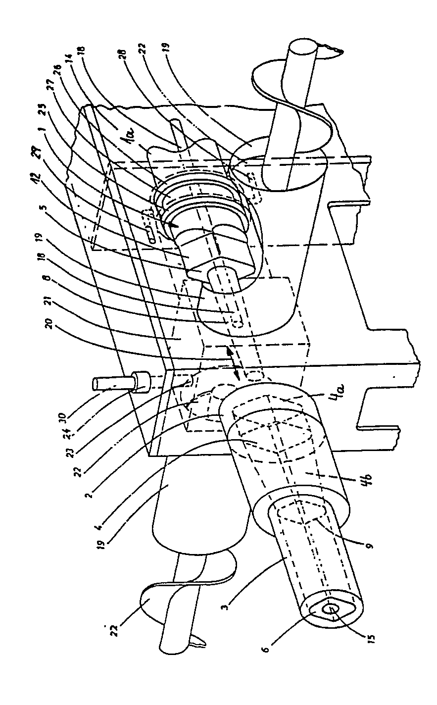
Description
Die Erfindung bezieht sich auf eine Presse nach dem Oberbegriff des Anspruches 1.The invention relates to a press according to the preamble of
Es ist eine Presse zum Herstellen von Briketts aus Holzspänen, Baumrinde und anderen Biomassen bekannt, die einen zylindrischen Stößel aufweist, der eine zugeführte Menge von Biomasse durch ein konusförmig ausgebildetes Rohr preßt. In diesem erfolgt eine Verdichtung und anschließend wird das verdichtete Gut durch ein Kühl- und Bremsrohr gedrückt, in dem es vor dem Ausschütten geglättet wird.A press for producing briquettes from wood chips, tree bark and other biomass is known, which has a cylindrical plunger which presses a supplied amount of biomass through a cone-shaped tube. This compresses and then the compacted material is pressed through a cooling and braking pipe, in which it is smoothed before being poured out.
Während des Preßvorganges im konusförmigen Rohr wird die Biomasse radial von außen nach innen gerichtet verdichtet. Die Wandreibung im Rohr und der Druck des Stößelschubs erzeugen eine den Brikettiervorgang unterstützende Temperaturerhöhung der Biomasse, die deren Moleküle aufschließt und ihnen die Elastizität nimmt, welche die Verfestigung des Brikettstranges beeinträchtigen würde.During the pressing process in the conical tube, the biomass is compressed radially from the outside inwards. The wall friction in the tube and the pressure of the tappet push generate a temperature increase of the biomass which supports the briquetting process, which unlocks its molecules and takes away the elasticity which would impair the solidification of the briquette strand.
Abgesehen von der Primärverdichtung der Biomasse durch die Stößelstirnfläche während der Durchschubperiode über die ganze Querschnittsfläche des Konuseinganges kann die radiale Verdichtung durch die Verengung des Konusrohres nur unzureichend erfolgen, denn die vorverdichtete, unter zunehmendem Radialdruck stehende Biomasse bildet tragende Kreisbögen, die das Durchdringen des Radialschubes bis zur Strangmitte behindert. Bei größeren Durchmessern des Brikettstranges kann es nicht ausbleiben, daß die inneren Partien weniger Dichte aufweisen und daß auch weniger Wärme von den Außenpartien kommend, die Mitte erreicht. Hierdurch leidet der homogene Zusammenhalt der Briketts.Apart from the primary compression of the biomass by the tappet end face during the push-through period over the entire cross-sectional area of the cone inlet, the radial compression by the narrowing of the cone tube can only take place inadequately, because the pre-compressed biomass, which is under increasing radial pressure, forms supporting arcs that prevent the radial thrust from penetrating disabled to the middle of the strand. With larger diameters of the briquette strand, it cannot fail to appear that the inner parts have less density and that less heat coming from the outer parts reaches the middle. As a result, the homogeneous cohesion of the briquettes suffers.
Aufgabe der Erfindung ist es, eine Presse zu schaffen, die eine gleichmäßige Dichte und Haltbarkeit der erzeugten Briketts bei herabgesetzter Antriebsleistung des Stößelantriebs gewährleistet.The object of the invention is to provide a press which ensures a uniform density and durability of the briquettes produced with reduced drive power of the ram drive.
Diese Aufgabe wird erfindungsgemäß durch die kennzeichnenden Merkmale des Anspruches 1 gelöst. Weitere vorteilhafte Merkmale beinhalten die Unteransprüche.This object is achieved by the characterizing features of
Die mit der Erfindung hauptsächlich erzielten Vorteile bestehen darin, daß durch die Ausbildung des Stößels mit einem Dorn geringeren Durchmessers, der sich mit seiner Spitze bis in die engste Zone des Verdichtungsrohres erstreckt, eine sekundäre Verdichtung der Biomasse teilweise oder vollständig radial von innen nach außen gerichtet erfolgt. Als Folge der radialen Verdichtung von innen nach außen weist der Brikettstrang eine zentrale Bohrung von der Dornspitze entsprechenden Durchmessers auf, so daß nach einer Ablängung des Stranges in Einzelstücke Hohlbriketts von hohem spezifischen Gewicht entstehen, die beispielsweise in Abhängigkeit von der Querschnittsform des Preßrohres runde, quadratische oder dreieckige Außenformen aufweisen können.The main advantages achieved with the invention are that by designing the plunger with a mandrel of smaller diameter, which extends with its tip into the narrowest zone of the compression tube, a secondary compression of the biomass is directed partially or completely radially from the inside to the outside he follows. As a result of the radial compression from the inside to the outside, the briquette strand has a central bore from the mandrel tip of the corresponding diameter, so that after cutting the strand into individual pieces, hollow briquettes of high specific weight are formed, which are round, square, for example, depending on the cross-sectional shape of the press tube or can have triangular outer shapes.
Auf die Mitte der Stößelstirnfläche ist ein konischer Dorn von etwa einem Drittel des Stößeldurchmessers am Fuß und ungefähr einem Viertel des Stößeldurchmessers am Vorderende aufgesetzt, dessen Länge sich bis in die engste Zone des Konusrohres erstreckt. Je nach dem Grad der Konizität des Verdichtungsdorns kann die des Preßdorns vermindert werden. Bei starker Konizität des Verdichtungsdorns kann das Preßrohr ohne Konizität ausgeführt sein. Das Preßrohr kann auch mit gleichbleibendem rechteckigen oder dreikantigem Innenquerschnitt in die Werkzeugaufnahme eingesetzt werden, wobei sie gegen Verdrehung gesichert sein muß. Entsprechend dem Querschnitt des Rohres wird der Umfang der Stößelspitze über die Länge der Eintauchtiefe des Stößels in das Preßrohr profilgerecht rechteckig oder dreieckig abgeflacht, während der größere hintere Teil des Stößels den kreisrunden Querschnitt behält und damit dessen Durchgang zum Antriebsgehäuse leicht abzudichten ist.A conical mandrel of about a third of the tappet diameter at the foot and about a quarter of the tappet diameter at the front end is placed on the center of the tappet end face, the length of which extends into the narrowest zone of the cone tube. Depending on the degree of taper of the compression mandrel, that of the compression mandrel can be reduced. If the compression mandrel is very tapered, the press tube can be designed without taper. The press tube can also be inserted into the tool holder with a constant rectangular or triangular internal cross section. whereby it must be secured against rotation. Depending on the cross-section of the tube, the circumference of the tappet tip is flattened rectangular or triangular over the length of the immersion depth of the tappet in the press tube, while the larger rear part of the tappet retains the circular cross-section and its passage to the drive housing can be easily sealed.
Der Verdichtungsdorn heizt sich bei seiner Arbeitsleistung auf und bedarf einer Wärmeableitung, die über den Stößel, seine Einspannung und seine Führung erfolgt. Da der Weg des Wärmeflusses von der thermisch besonders belasteten Dornspitze bis zur Einspannung sehr lang ist, der Querschnitt des Dorns relativ klein ist und das Wärmeleitvermögen von Stahl für die Wärmeführung nicht ausreicht, ist ein die Wärme ableitendes Hilfsmittel, beispielsweise ein in eine zentrale Bohrung des Dorns eingepreßter Kupferstab, der bis in den Stößel hineingeführt ist, oder eine Füllung des Dorns mit Natrium vorgesehen.The compression mandrel heats up during its work and requires heat dissipation, which takes place via the plunger, its clamping and its guidance. Since the path of the heat flow from the thermally particularly stressed mandrel tip to the clamping is very long, the cross section of the mandrel is relatively small and the thermal conductivity of steel is not sufficient for the heat conduction, a heat-dissipating aid, for example one in a central bore of the Mandrel pressed copper rod, which is inserted into the plunger, or a filling of the mandrel with sodium provided.
Bei der radialen Verdrängungs- und Verdichtungsarbeit des mit dem Stößel oszillierenden Dorns treten an seiner Umfangsfläche infolge seiner Keilwirkung enorme Pressungen auf. Würde die Beschickung in den Eingang des Preßrohres nicht völlig gleichmäßig erfolgen, so würde der Dorn bei seinem Vorlaufhub so hohe einseitige Druckkräfte erhalten, daß er sich aus der zentralen Mitte herausbiegt. Um dieses zu vermeiden, ist der nach dem Rücklauf des Stößels freiwerdende Raum der Stößelbahn in der vor dem Preßrohr liegenden Vorkammer allseits um den Verdichtungsdorn herum mit Biomasse aufzufüllen. Dieses wird durch doppelte, von beiden Seiten der Stößelpresse an die Vorkammer herangeführte Beschickungskanäle mit entsprechenden Förderein richtungen erreicht. Unterstützt wird die Füllung des periodisch vom Stößel freigegebenen und verdrängten Hohlraumes dadurch, daß der Stößelhub groß genug bemessen ist, um der Stirnfläche des Stößels auch eine rückwärtige Eintauchtiefe zu geben, wodurch erstens Biomasse in die freigelegte Stößelbahn gesaugt wird und zweitens ein ausreichender Zeitquerschnitt für den Eintritt der geförderten Biomasse in die Stößelbahn geschaffen ist.During the radial displacement and compression work of the mandrel oscillating with the plunger, enormous pressures occur on its peripheral surface due to its wedge effect. If the feed into the inlet of the press tube were not completely uniform, the mandrel would receive such high one-sided compressive forces during its advance stroke that it bends out of the central center. In order to avoid this, the space of the tappet path in the prechamber lying in front of the press tube after the ram has returned must be filled with biomass on all sides around the compression mandrel. This is achieved by means of double feed channels with corresponding conveyors, which are brought to the prechamber from both sides of the ram press directions reached. The filling of the cavity, which is periodically released and displaced by the tappet, is supported by the fact that the tappet stroke is dimensioned large enough to give the end face of the tappet also a backward immersion depth, whereby firstly biomass is sucked into the uncovered tappet path and secondly a sufficient time cross section for the Entry of the subsidized biomass into the ram is created.
Die in die Stößelbahn im kurzen Zeitraum ihrer Öffnung gelangte Biomasse hat einen mehr oder weniger großen Luftanteil. Eine dicht vor der Öffnung des Preßrohres in die obere Wand der Spänekammer eingelassene Entlüftungsbohrung sorgt für den Austritt des Luftanteils aus der Stößelbahn, wenn die Stirnfläche des Stößels die Biomasse in Richtung Preßrohr verschiebt. Eine ventilähnliche Einrichtung im angeschlossenen Entlüftungsrohr verhindert das Ansaugen von Beiluft in die Stößelbahn beim Rücklauf des Stößels.The biomass that got into the ram in the short period of its opening has a more or less large amount of air. A vent hole inserted just before the opening of the press tube in the upper wall of the chip chamber ensures that the air portion escapes from the tappet path when the end face of the tappet moves the biomass in the direction of the press tube. A valve-like device in the connected ventilation pipe prevents additional air from being sucked into the tappet path when the tappet returns.
Die Stößelpresse umfaßt im wesentlichen einen oszillierend angetriebenen Stößel 1, der gegenüberstehend eines Preßrohres 2 angeordnet ist und dem eine Spänekammer 21 vorgeschaltet ist. Dieser Kammer 21 sind Beschickungsschächte 19,20 zugerichtet, in denen Förderschnecken 22 angeordnet sind, die die Kammer 21 von zwei gegenüberliegenden Seiten mit Biomasse beschicken. In der Oberwand 23 der Kammer 21, unmittelbar vor der Eintrittsöffnung des Preßrohres 2 und oberhalb der Stößelbewegungsbahn 20 liegend, ist eine Entlüftungsleitung 30 mit einem Ventil 24 angeordnet.The ram press essentially comprises an oscillatingly driven
Der Stößel umfaßt einen, im Antriebsgehäuse 14 geführten und im Querschnitt runden Schaft 1a, an den sich ein Stößelkopf 12 anschließt, der an seiner Stirnseite 5 mit einem axial vorstehend angeordneten Dorn 8 verbunden ist. Dieser weist einen kleineren Durchmesser auf als der Stößelkopf 12 und wird bei einem Preßvorgang in das Preßrohr 2 hineinbewegt, wo es die aus der Kammer 21 mitgeführte Biomasse radial und axial zu Briketts zusammenpreßt.The plunger comprises a shaft 1a, which is guided in the
Das Preßrohr 2 kann, wie die Zeichnung beispielsweise darstellt, einen polygonalen Querschnitt, wie dreieckig, viereckig oder dergleichen, aufweisen, wobei es pyramidenförmig ausgeführt ist und sich in Preßrichtung des Stößels 1 verengt. Anschließend an das Preßrohr 2 ist ein weiteres Rohr vorgesehen, das den Endquerschnitt 9 des Preßrohres 2 aufweist und als Kühlrohr 3 ausgeführt ist, aus dem über eine Öffnung 6 der mit einer zentralen Öffnung 15 versehene Brikettstrang austritt.As the drawing shows, for example, the press tube 2 can have a polygonal cross section, such as triangular, quadrangular or the like, it being pyramid-shaped and narrowing in the pressing direction of the
Bei einer solchen Ausführung des Preßrohres 2 ist der Dorn 8 vorzugsweise über die Länge der Eintauchtiefe in das Preßrohr 2 konisch ausgeführt. Der anschließende Stößelkopf 12 ist viereckig ausgeführt. Dieser weist im Preßrohr einen etwa entsprechend gleichgroßen viereckigen Aufnahmeraum 4a mit der Eintrittsöffnung 4 auf, in die der Kopf 12 bei einem Preßvorgang eintaucht.In such an embodiment of the press tube 2, the
Nach einer weiteren Ausführungsform kann der Dorn 8 auch eine dem Preßrohr 2 kongruente Querschnittsform aufweisen, d.h. bei einem viereckigen Innenquerschnitt des Preßrohres 2 ist der Dorn 8 ebenfalls im Querschnitt viereckig ausgeführt.According to a further embodiment, the
Auch kann da Preßrohr 2 konisch ausgeführt sein, wobei der Dorn 8 dann eine entsprechende konische Form aufweist.The press tube 2 can also be designed conically, the
Ferner ist nach einer weiteren Ausführungsform vorgesehen, daß das Preßrohr 2 einen polygonalen Querschnitt mit über seine Länge gleichbleibender Querschnittsfläche aufweist und der Dorn eine mit dieser Form korrespondierende Querschnittsfläche besitzt.Furthermore, according to a further embodiment it is provided that the press tube 2 has a polygonal cross section with a cross-sectional area that is constant over its length, and that the mandrel has a cross-sectional area corresponding to this shape.
Der Hub des Stößels 1 sollte ein solches Maß aufweisen, daß sich genügend Biomasse um den Dorn 8 herum zu fördern läßt, damit der Dorn 8 beim Vorstoßen zum Pressen gleichmäßig radial belastet wird. Insbesondere soll der Hub des Stößels 1 länger als die Breite des Beschickungsschachtes 19 der Kammer 21 sein.The stroke of the
Zur Ableitung von Wärme während des Preßvorganges vom Dorn 8 ist in diesem ein hochwärmeleitendes Material eingebettet, das z.B. aus einem zentralen Kupferstrang 18 oder einer Natriumfüllung besteht.To dissipate heat during the pressing process from the
In der Rückwand der mit Biomasse beschickten Spänekammer 21 sind außer einer vom Stößelschaft durchdrungenen Staubdichtung noch zwei weitere nebeneinanderliegende Ölabdichtungen 25 und 26 zum Antriebsgehäuse 14 hin vorgesehen, zwischen denen ein ringförmiger Hohlraum 27 angeordnet ist, der von einem kontinuierlichen Ölstrom durchflossen ist, welcher eine Zuführleitung 28 und eine Ablaßleitung 29 aufweist.In the rear wall of the
Claims (14)
Applications Claiming Priority (2)
| Application Number | Priority Date | Filing Date | Title |
|---|---|---|---|
| DE3744485 | 1987-12-30 | ||
| DE3744485 | 1987-12-30 |
Publications (2)
| Publication Number | Publication Date |
|---|---|
| EP0322575A2 true EP0322575A2 (en) | 1989-07-05 |
| EP0322575A3 EP0322575A3 (en) | 1990-05-30 |
Family
ID=6343821
Family Applications (1)
| Application Number | Title | Priority Date | Filing Date |
|---|---|---|---|
| EP88119845A Withdrawn EP0322575A3 (en) | 1987-12-30 | 1988-11-29 | Press for making hollow pellets |
Country Status (1)
| Country | Link |
|---|---|
| EP (1) | EP0322575A3 (en) |
Family Cites Families (7)
| Publication number | Priority date | Publication date | Assignee | Title |
|---|---|---|---|---|
| DE148227C (en) * | ||||
| DE96004C (en) * | ||||
| FR629106A (en) * | 1927-02-14 | 1927-11-04 | Buhler Freres | Press for the production of hollow conglomerates |
| US2833633A (en) * | 1955-01-10 | 1958-05-06 | John R Hecht | Apparatus for forming logs of compressible materials |
| FR2366929A1 (en) * | 1976-10-06 | 1978-05-05 | Wetstein Leon | Press for compacting cotton waste - has hydraulic ram operating in heated compaction chamber and extrusion tube with cut=off knife |
| US4436526A (en) * | 1982-06-25 | 1984-03-13 | Hmvh Corporation | Method for making an artificial fuel log |
| US4599091A (en) * | 1984-09-14 | 1986-07-08 | Lee Andrew O | Briquette forming apparatus |
-
1988
- 1988-11-29 EP EP88119845A patent/EP0322575A3/en not_active Withdrawn
Also Published As
| Publication number | Publication date |
|---|---|
| EP0322575A3 (en) | 1990-05-30 |
Similar Documents
| Publication | Publication Date | Title |
|---|---|---|
| EP1864790A2 (en) | Pressure device, in particular for dehumidifying metal cuttings or grinding debris | |
| CH672354A5 (en) | ||
| DE2714993A1 (en) | METHOD OF DELIVERING FIBROUS LIGNOCELLULOSE RAW MATERIAL TO A PRESSURE VESSEL | |
| DE102010012838B4 (en) | Apparatus for the production of compacts | |
| DE1627722B2 (en) | Process for the powder metallurgical production of rods and tubes | |
| DD285569A5 (en) | HYDRAULIC IMPACT TOOL | |
| DE2338110A1 (en) | BRIQUETTING PRESS | |
| DE2334634A1 (en) | AUTOMATIC PRESSURE REGULATOR | |
| DE1938024A1 (en) | Extrusion press for the production of light metal profiles | |
| DE8590051U1 (en) | Device for compressing material | |
| EP0322575A2 (en) | Press for making hollow pellets | |
| DE2509490B2 (en) | Closure piece on an indirect metal extrusion press for light and heavy metals | |
| DE69827571T2 (en) | glow plug | |
| DE3208844C2 (en) | ||
| DE3837714A1 (en) | Press for producing hollow briquettes | |
| EP1629965A2 (en) | Apparatus for manufacturing of vegetable oils | |
| DE29908434U1 (en) | Screw press for pressing out liquid-containing foods, in particular oil-containing seeds | |
| EP0762118B1 (en) | Method of manufacturing a chromatography column | |
| DE3730214C2 (en) | ||
| DE10245284A1 (en) | For the production of wood blocks, from an extruded strand of compressed and glued wood particles/chips, the wood material is heated on entering the filling/press zone of the extrusion press | |
| DE8907312U1 (en) | Piercing device for piercing a cooling liquid line in a cooling device to be disposed of | |
| DE2144071A1 (en) | Device for the production of pellets from a powdery material | |
| DE1145017B (en) | Hydraulic power cylinder unit | |
| DE19681469B4 (en) | Hydraulic clearance compensation element for a valve train of an internal combustion engine | |
| DE3902689C1 (en) | Device for introducing milling aid bodies into mills, in particular agitator mills |
Legal Events
| Date | Code | Title | Description |
|---|---|---|---|
| PUAI | Public reference made under article 153(3) epc to a published international application that has entered the european phase |
Free format text: ORIGINAL CODE: 0009012 |
|
| AK | Designated contracting states |
Kind code of ref document: A2 Designated state(s): AT CH DE IT LI SE |
|
| PUAL | Search report despatched |
Free format text: ORIGINAL CODE: 0009013 |
|
| AK | Designated contracting states |
Kind code of ref document: A3 Designated state(s): AT CH DE IT LI SE |
|
| STAA | Information on the status of an ep patent application or granted ep patent |
Free format text: STATUS: THE APPLICATION IS DEEMED TO BE WITHDRAWN |
|
| 18D | Application deemed to be withdrawn |
Effective date: 19901201 |