EP0322436B1 - Halbautomatische vorrichtung zur kontinuierlichen markierung der xy-koordinaten von singulären punkten einer beweglichen fläche - Google Patents
Halbautomatische vorrichtung zur kontinuierlichen markierung der xy-koordinaten von singulären punkten einer beweglichen fläche Download PDFInfo
- Publication number
- EP0322436B1 EP0322436B1 EP19880905904 EP88905904A EP0322436B1 EP 0322436 B1 EP0322436 B1 EP 0322436B1 EP 19880905904 EP19880905904 EP 19880905904 EP 88905904 A EP88905904 A EP 88905904A EP 0322436 B1 EP0322436 B1 EP 0322436B1
- Authority
- EP
- European Patent Office
- Prior art keywords
- movement
- operator
- checked
- fabric
- coordinate
- Prior art date
- Legal status (The legal status is an assumption and is not a legal conclusion. Google has not performed a legal analysis and makes no representation as to the accuracy of the status listed.)
- Expired - Lifetime
Links
- 230000004807 localization Effects 0.000 title description 6
- 239000004744 fabric Substances 0.000 claims description 53
- 230000007547 defect Effects 0.000 claims description 26
- 230000033001 locomotion Effects 0.000 claims description 21
- 239000000463 material Substances 0.000 claims description 8
- 239000002184 metal Substances 0.000 claims description 2
- 230000015572 biosynthetic process Effects 0.000 claims 1
- 238000006073 displacement reaction Methods 0.000 abstract description 12
- 239000004753 textile Substances 0.000 description 7
- 210000001519 tissue Anatomy 0.000 description 7
- 238000009826 distribution Methods 0.000 description 6
- 238000005520 cutting process Methods 0.000 description 3
- 239000005338 frosted glass Substances 0.000 description 3
- 239000003550 marker Substances 0.000 description 3
- 230000009471 action Effects 0.000 description 2
- 230000005540 biological transmission Effects 0.000 description 2
- 238000013479 data entry Methods 0.000 description 2
- 230000000694 effects Effects 0.000 description 2
- 238000012986 modification Methods 0.000 description 2
- 230000004048 modification Effects 0.000 description 2
- 238000006677 Appel reaction Methods 0.000 description 1
- 241000895680 Stylosanthes guianensis Species 0.000 description 1
- 238000000151 deposition Methods 0.000 description 1
- 238000001514 detection method Methods 0.000 description 1
- 210000001061 forehead Anatomy 0.000 description 1
- 230000006870 function Effects 0.000 description 1
- 238000005286 illumination Methods 0.000 description 1
- 230000006872 improvement Effects 0.000 description 1
- 238000007689 inspection Methods 0.000 description 1
- 238000009940 knitting Methods 0.000 description 1
- 238000004519 manufacturing process Methods 0.000 description 1
- 238000005259 measurement Methods 0.000 description 1
- 238000000034 method Methods 0.000 description 1
- 238000005457 optimization Methods 0.000 description 1
- 238000003825 pressing Methods 0.000 description 1
- 238000003860 storage Methods 0.000 description 1
- 230000009897 systematic effect Effects 0.000 description 1
- 230000001131 transforming effect Effects 0.000 description 1
- 238000009941 weaving Methods 0.000 description 1
- 239000002023 wood Substances 0.000 description 1
Images

Classifications
-
- D—TEXTILES; PAPER
- D06—TREATMENT OF TEXTILES OR THE LIKE; LAUNDERING; FLEXIBLE MATERIALS NOT OTHERWISE PROVIDED FOR
- D06H—MARKING, INSPECTING, SEAMING OR SEVERING TEXTILE MATERIALS
- D06H3/00—Inspecting textile materials
Definitions
- the present invention relates to a semi-automatic device for continuously locating by an operator the X and Y coordinates of singular points within a surface such as for example a sheet, a film or fabric or a plate. rigid in motion, or their image on a screen.
- singular points is meant in particular local defects, especially within a fabric, such as for example defects in material, knitting or weaving or even color defects.
- the term “singular points” also denotes knots or other irregularities which may appear on a plate, in particular of wood, or even a local insert. In other words, we define by “singular points” any visible element which distinguishes itself in a uniform set.
- this device delivers a label on which are written the fabric code and the number of defects as well as their distribution according to the length.
- this device does not allow the location of faults to be listed exactly.
- the exact distribution of defects within a piece of fabric that is to say an overall estimate of the quality of the fabric, has an impact on the rationalization of its use.
- the cutting made within a piece of fabric is a function of the two-dimensional distribution of the defects within said piece.
- the present invention aims to overcome these drawbacks.
- its main goal is to allow location according to two coordinates, that is to say according to the coordinates of the plane observed.
- It relates more particularly to a device allowing the identification of faults on a piece of fabric and which, moreover, also allows the real localization of said faults after constitution of a mattress from this fabric to carry out manufacturing operations.
- the solution described in this document generally consists of scrolling the material to be inspected (tissue) on a control plane and of detecting faults by means of a system using a light source which is captured. by a receiving element arranged on the other side of the face of the textile. Consequently, depending on the amount of light transmitted, it is therefore possible, starting from an average level, to detect either an excessive transmission corresponding to a lighter hole or zone in the tissue, or, conversely, a transmission insufficient corresponding to more opaque areas.
- the invention proposes a device making it possible to locate the two coordinates of one of the singular points likely to appear on a surface and to record them in order to deliver an accurate statement of the two-dimensional distribution of said singular points.
- the following description relates to a device for locating local faults within a fabric or a fabric.
- the invention cannot be limited to this embodiment, and that any surface having singular points as defined in the preamble of this description, can be analyzed by a device of the same type, conforming to the invention, with a few structural adjustments.
- the locating device basically comprises a reading plane (1), slightly inclined, having an opening closed by a frosted glass (2). Behind this frosted glass is located a light source emitting through said frosted glass.
- Said inclined plane (1) comprises along two of its opposite edges two rollers (3,4) intended to allow the movement of the piece of fabric (10) controlled. These rollers (3) and (4) are conventionally driven by a motor, not shown;
- an input rule (5) is fixed (a rule consisting for example of 192 indicator lights located every centimeter), located transversely to the direction of travel of the piece of fabric to be checked.
- This seizure rule also comprises slides, not shown, allowing the attachment and adjustment in position of width sensors (8) and (9) serving as elements for controlling the width of the fabric.
- width sensors (8) and (9) serving as elements for controlling the width of the fabric.
- width sensors means the width of the piece of fabric.
- these sensors consist of a plurality of photoelectric cells having an average center distance of the order of five millimeters. The variations in width are recorded within the central unit (11) and, conventionally, only the minimum width, the maximum as well as the average width of said piece of fabric finally emerge.
- the gripping rule (5) further comprises at its forehead, that is to say at the level of the meeting of the piece of fabric which passes with said rule, a ramp of photodiodes (15), the lighting is controlled by a manipulator (12) located at a central input and recording unit (11), the latter being electrically connected to the input rule (5).
- a measuring wheel (6) intended to measure the length of the movement of the piece of fabric (10), is fixed by means of a support (7) to the grip rule (5).
- This metering wheel allows in particular to measure the length of each piece of fabric.
- the central input and recording unit (11) comprises a keyboard (13) making it possible to record the code or the reference of the controlled piece of fabric. It also includes a display (14) for viewing the reference of the piece of fabric as well as the code listing the identified fault. The selection of one or other of the indices of the code likely to be displayed on the member (14) is performed by the manipulator (12) by actuating it on one of its two degrees of freedom.
- the central recording and recording unit (11) comprises a printer which delivers, after checking each piece of fabric, a label intended to be affixed to said piece of fabric (10), said label. comprising in addition to the reference of said piece of fabric, the extremes and the average of the width of said pieces, the type of defect identified and for each of the faults their X and Y coordinates.
- the piece of fabric (10) to be controlled being in place on the control plane (1), its advancement is controlled by means of a pedal (not shown) actuated by the operator.
- a pedal not shown
- the control of the movement of the piece of fabric (10) can be ensured at the level of the manipulator (12) by simple rotation of said manipulator. In this case, the latter would then have three degrees of freedom.
- the operator When the operator sees a defect of any kind, it causes the positioning (displacement) of the visible mark constituted in the embodiment described by the illumination of one of the photodiodes constituting the ramp (15), and matches said visible reference with the observed defect.
- the defect When the defect is located directly above the photodiode, namely on the one hand the vertical alignment along the Y coordinate, that is to say along the transverse axis with respect to the direction of travel of the piece of fabric (10), but also plumb with the photodiode considered on the X coordinate, the operator presses the end of the manipulator (12), causing the immediate entry of the X, Y coordinates of the identified fault. This entry must then be stored in the central entry and recording unit (11).
- the operator actuates the manipulator (12) according to another degree of freedom in order to select the category of the identified fault.
- the operator also enters it by simply pressing the end of the manipulator (12).
- the category of the fault identified is then also recorded in the central data entry and recording unit.
- the operator then continues to check the pieces of fabric (10) by again scrolling said piece.
- the identification of faults within the piece of fabric is effected by a simple back-and-forth movement of the visible mark in this case constituted by photodiodes, thus transforming an activity particularly tedious in an almost fun activity.
- the exact two-dimensional determination of the distribution of defects within a part of fabric but also within any surface, or its image on a screen allows an optimization of their use where a significant saving.
- the device according to the invention is applied to locating singular points of any type of flat surface, and in particular in the textile industry in locating local faults.
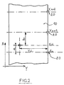
- Such a fault identification system can, as illustrated by FIG. 2, be used to allow the actual location of said faults after constitution of a mattress.
Landscapes
- Engineering & Computer Science (AREA)
- Chemical & Material Sciences (AREA)
- Materials Engineering (AREA)
- Textile Engineering (AREA)
- Treatment Of Fiber Materials (AREA)
- Length Measuring Devices With Unspecified Measuring Means (AREA)
Claims (8)
dadurch gekennzeichnet, daß sie darüberhinaus enthält:
_ Mittel zum Messen der Breite des Materials im Laufe der Kontrolle;
_ Mittel zum Ermitteln der zweiten Koordinate (Y), die folgendes aufweisen:
dadurch gekennzeichnet, daß sie darüberhinaus enthält:
_ Mittel zum Messen der Breite des Materials im Laufe der Kontrolle;
_ Mittel zum Erfassen der zweiten Koordinate (Y), wobei diese durch folgendes gebildet sind:
_ wobei die ersten Mittel zum Positionieren (Verschieben) durch eine Photodiodenleiste (15) gebildet werden, die in die querverlaufende Erfassungsleiste (5) integriert ist;
_ wobei die ersten und zweiten Mittel von der Bedienungsperson mittels eines Manipulators (12) gesteuert werden;
_ wobei der Manipulator (12) durch die Bedienungsperson längs zweier Freiheitsgrade bewegt werden kann, wobei eine Bewegung längs des ersten Freiheitsgrades ein Bewegen der sichtbaren Markierung auf der Photodiodenleiste (15) steuert, und wobei ein Bewegen des Manipulators (12) entlang des zweiten Freiheitsgrades ein Bewegen des Codes, der die verschiedenen Kategorien der beobachteten Fehler innerhalb des Stoffes (10) auf einer Anzeige (14) in der zentralen Einheit (11) aufnimmt, in der einen oder anderen Richtung steuert.
Applications Claiming Priority (2)
| Application Number | Priority Date | Filing Date | Title |
|---|---|---|---|
| FR8710093 | 1987-07-09 | ||
| FR8710093A FR2617958B1 (fr) | 1987-07-09 | 1987-07-09 | Dispositif semi-automatique de reperage en continu des coordonnees xy de points singuliers au sein d'une surface en mouvement |
Publications (2)
| Publication Number | Publication Date |
|---|---|
| EP0322436A1 EP0322436A1 (de) | 1989-07-05 |
| EP0322436B1 true EP0322436B1 (de) | 1991-06-05 |
Family
ID=9353231
Family Applications (1)
| Application Number | Title | Priority Date | Filing Date |
|---|---|---|---|
| EP19880905904 Expired - Lifetime EP0322436B1 (de) | 1987-07-09 | 1988-07-06 | Halbautomatische vorrichtung zur kontinuierlichen markierung der xy-koordinaten von singulären punkten einer beweglichen fläche |
Country Status (3)
| Country | Link |
|---|---|
| EP (1) | EP0322436B1 (de) |
| FR (1) | FR2617958B1 (de) |
| WO (1) | WO1989000623A1 (de) |
Cited By (1)
| Publication number | Priority date | Publication date | Assignee | Title |
|---|---|---|---|---|
| KR100733497B1 (ko) | 2006-07-20 | 2007-06-28 | 한국봉제기술연구소 | 전자 감응 장치를 이용한 반자동 검단 시스템 |
Families Citing this family (1)
| Publication number | Priority date | Publication date | Assignee | Title |
|---|---|---|---|---|
| WO1996009431A1 (de) * | 1994-09-21 | 1996-03-28 | Wolf Merz Ag | Verfahren zur verarbeitung von warenbahnen |
Family Cites Families (1)
| Publication number | Priority date | Publication date | Assignee | Title |
|---|---|---|---|---|
| GB1077561A (en) * | 1964-02-18 | 1967-08-02 | Omron Tateisi Electronics Co | System of detecting and marking defects in a moving web |
-
1987
- 1987-07-09 FR FR8710093A patent/FR2617958B1/fr not_active Expired - Lifetime
-
1988
- 1988-07-06 WO PCT/FR1988/000360 patent/WO1989000623A1/fr not_active Ceased
- 1988-07-06 EP EP19880905904 patent/EP0322436B1/de not_active Expired - Lifetime
Cited By (1)
| Publication number | Priority date | Publication date | Assignee | Title |
|---|---|---|---|---|
| KR100733497B1 (ko) | 2006-07-20 | 2007-06-28 | 한국봉제기술연구소 | 전자 감응 장치를 이용한 반자동 검단 시스템 |
Also Published As
| Publication number | Publication date |
|---|---|
| FR2617958A1 (fr) | 1989-01-13 |
| WO1989000623A1 (fr) | 1989-01-26 |
| EP0322436A1 (de) | 1989-07-05 |
| FR2617958B1 (fr) | 1990-05-11 |
Similar Documents
| Publication | Publication Date | Title |
|---|---|---|
| US4972494A (en) | Package inspection system | |
| EP0330495A2 (de) | Verpackungsbeaufsichtigungssystem | |
| FR2552252A1 (fr) | Lecteur mixte pour cartes a piste magnetique et/ou a puce electronique | |
| FR2514171A1 (fr) | Procede et dispositif de generation d'un dessin verifie | |
| CH617278A5 (de) | ||
| CN102252608B (zh) | 光学测量方法和装置 | |
| EP0622610A1 (de) | Verfahren und Anordnung zum Eichen der Dickenmessanordnung des Querprofils eines flächigen Gutes | |
| JP2008510973A (ja) | タバコ加工産業の製品の外観検査 | |
| EP0322436A1 (de) | Halbautomatische vorrichtung zur kontinuierlichen markierung der xy-koordinaten von singulären punkten einer beweglichen fläche | |
| FR2633748A1 (fr) | Procede et dispositif d'identification d'outil d'ecriture | |
| EP0203010A1 (de) | Vorrichtung zur berührungslosen Messung von Abmessungen eines Parallelepipedons | |
| FR2683791A3 (fr) | Dispositif pour le controle optique de produits sosu emballage. | |
| EP0466892B1 (de) | Verfahren und vorrichtung zur messung der verwindung eines textilgarns | |
| JP2002257837A (ja) | 試薬パッドの位置及び厚みを検出することによる尿試料供試用ノズル位置の制御方法 | |
| TW200537587A (en) | Method and device for detecting patterns on a substrate | |
| EP0929791A1 (de) | Verfahren und vorrichtung zur messung der verformung von führungsrohren | |
| EP1531482A2 (de) | Vorrichtung und Verfahren zur Überprüfung der Aussenfläche von Kernreaktorbrennsäben | |
| FR2634025A1 (fr) | Adaptateur de brochage pour le test de circuits imprimes de haute densite | |
| FR2537716A1 (fr) | Dispositif de mesure automatique et sans contact du volume d'une couche deposee sur un substrat | |
| FR2497385A1 (fr) | Selecteur de programme de lecteur d'enregistrement | |
| EP0216705B1 (de) | Nachprüfungsvorrichtung für durchlaufende zylinderförmige Gegenstände mit Verwendung eindringender Strahlung | |
| FR2752937A1 (fr) | Installation pour l'acquisition de points singuliers dans un materiau plan et son application a l'acquisition de defauts isoles ou de zones de defauts dans une bande textile | |
| EP0180512B1 (de) | Vorrichtung zur Lokalisierung und Markierung von leuchtenden Objekten | |
| CA1301364C (fr) | Procede et dispositif portatif pour saisir, memoriser et eventuellement traiter et reproduire des signes graphiques figurant sur un support quelconque | |
| FR2547473A1 (fr) | Dispositif pour la lecture et l'analyse numerique ligne par ligne d'un motif lumineux eventuellement obtenu par projection et appareillage pour la mise en oeuvre dudit dispositif |
Legal Events
| Date | Code | Title | Description |
|---|---|---|---|
| PUAI | Public reference made under article 153(3) epc to a published international application that has entered the european phase |
Free format text: ORIGINAL CODE: 0009012 |
|
| AK | Designated contracting states |
Kind code of ref document: A1 Designated state(s): BE CH DE GB IT LI |
|
| 17P | Request for examination filed |
Effective date: 19890621 |
|
| 17Q | First examination report despatched |
Effective date: 19901112 |
|
| GRAA | (expected) grant |
Free format text: ORIGINAL CODE: 0009210 |
|
| AK | Designated contracting states |
Kind code of ref document: B1 Designated state(s): BE CH DE GB IT LI |
|
| PG25 | Lapsed in a contracting state [announced via postgrant information from national office to epo] |
Ref country code: IT Free format text: LAPSE BECAUSE OF FAILURE TO SUBMIT A TRANSLATION OF THE DESCRIPTION OR TO PAY THE FEE WITHIN THE PRE;WARNING: LAPSES OF ITALIAN PATENTS WITH EFFECTIVE DATE BEFORE 2007 MAY HAVE OCCURRED AT ANY TIME BEFORE 2007. THE CORRECT EFFECTIVE DATE MAY BE DIFFERENT FROM THE ONE RECORDED.SCRIBED TIME-LIMIT Effective date: 19910605 Ref country code: GB Effective date: 19910605 |
|
| PGFP | Annual fee paid to national office [announced via postgrant information from national office to epo] |
Ref country code: CH Payment date: 19910708 Year of fee payment: 4 |
|
| REF | Corresponds to: |
Ref document number: 3863173 Country of ref document: DE Date of ref document: 19910711 |
|
| PGFP | Annual fee paid to national office [announced via postgrant information from national office to epo] |
Ref country code: DE Payment date: 19910722 Year of fee payment: 4 |
|
| PGFP | Annual fee paid to national office [announced via postgrant information from national office to epo] |
Ref country code: BE Payment date: 19910809 Year of fee payment: 4 |
|
| GBV | Gb: ep patent (uk) treated as always having been void in accordance with gb section 77(7)/1977 [no translation filed] | ||
| PLBE | No opposition filed within time limit |
Free format text: ORIGINAL CODE: 0009261 |
|
| STAA | Information on the status of an ep patent application or granted ep patent |
Free format text: STATUS: NO OPPOSITION FILED WITHIN TIME LIMIT |
|
| 26N | No opposition filed | ||
| PG25 | Lapsed in a contracting state [announced via postgrant information from national office to epo] |
Ref country code: CH Effective date: 19920731 Ref country code: LI Effective date: 19920731 Ref country code: BE Effective date: 19920731 |
|
| BERE | Be: lapsed |
Owner name: GUILBAUD JEAN-PIERRE Effective date: 19920731 |
|
| REG | Reference to a national code |
Ref country code: CH Ref legal event code: PL |
|
| PG25 | Lapsed in a contracting state [announced via postgrant information from national office to epo] |
Ref country code: DE Effective date: 19930401 |