EP0321823A1 - Méthode et dispositif pour le découplage de la puissance active et réactive dans une liaison de deux réseaux haute tension en courant continu - Google Patents
Méthode et dispositif pour le découplage de la puissance active et réactive dans une liaison de deux réseaux haute tension en courant continu Download PDFInfo
- Publication number
- EP0321823A1 EP0321823A1 EP88120742A EP88120742A EP0321823A1 EP 0321823 A1 EP0321823 A1 EP 0321823A1 EP 88120742 A EP88120742 A EP 88120742A EP 88120742 A EP88120742 A EP 88120742A EP 0321823 A1 EP0321823 A1 EP 0321823A1
- Authority
- EP
- European Patent Office
- Prior art keywords
- voltage
- control
- controller
- reactive power
- level
- Prior art date
- Legal status (The legal status is an assumption and is not a legal conclusion. Google has not performed a legal analysis and makes no representation as to the accuracy of the status listed.)
- Granted
Links
Images


Classifications
-
- H—ELECTRICITY
- H02—GENERATION; CONVERSION OR DISTRIBUTION OF ELECTRIC POWER
- H02J—CIRCUIT ARRANGEMENTS OR SYSTEMS FOR SUPPLYING OR DISTRIBUTING ELECTRIC POWER; SYSTEMS FOR STORING ELECTRIC ENERGY
- H02J3/00—Circuit arrangements for ac mains or ac distribution networks
- H02J3/36—Arrangements for transfer of electric power between ac networks via a high-tension dc link
-
- Y—GENERAL TAGGING OF NEW TECHNOLOGICAL DEVELOPMENTS; GENERAL TAGGING OF CROSS-SECTIONAL TECHNOLOGIES SPANNING OVER SEVERAL SECTIONS OF THE IPC; TECHNICAL SUBJECTS COVERED BY FORMER USPC CROSS-REFERENCE ART COLLECTIONS [XRACs] AND DIGESTS
- Y02—TECHNOLOGIES OR APPLICATIONS FOR MITIGATION OR ADAPTATION AGAINST CLIMATE CHANGE
- Y02E—REDUCTION OF GREENHOUSE GAS [GHG] EMISSIONS, RELATED TO ENERGY GENERATION, TRANSMISSION OR DISTRIBUTION
- Y02E60/00—Enabling technologies; Technologies with a potential or indirect contribution to GHG emissions mitigation
- Y02E60/60—Arrangements for transfer of electric power between AC networks or generators via a high voltage DC link [HVCD]
Definitions
- the invention relates to a method for regulating the active and reactive power transmission between two electrical networks, which are connected via a high-voltage direct-current transmission link ("HVDC" link), in particular as a short coupling, according to the preamble of claim 1.
- the invention further relates to a control device for active and reactive power transmission.
- HVDC link shows a known control structure for a high-voltage direct current transmission link ("HVDC link").
- Two, in particular three-phase power supply networks A and B are each coupled to the ends of an HVDC link via a controllable converter UR1 and UR2.
- the electrical parameters of the line are provided with the reference symbols Id for the direct current and Ud for the direct voltage.
- a smoothing inductance Ld for damping harmonics in the HVDC link is shown as an example.
- one of the two inverters UR1, UR2 works as a rectifier and the other as an inverter. 1 it is assumed that the converter UR1 works in rectifier mode and the converter UR2 works in inverter mode.
- Two cascade controls are used to control the active power P and the line voltage U or the reactive power Q in one of the two networks. These each act on one of the two inverters and are shown in FIG. 1 on the left side of the vertical dashed line marked II.
- the subordinate or higher-level controllers of the respective cascade control are shown on the right or left of a further dashed line marked I.
- the control deviation ⁇ P formed by means of a mixing point 1 from an active power setpoint P * and an active power actual value P is fed to a superordinate active power controller Rp. Its output signal serves as setpoint Id * for the value of the direct current on the HVDC link.
- the associated control deviation is formed by means of a second mixing point 2 by comparison with the actual DC value Id and fed to a subordinate direct current controller Ri.
- the second cascade control acts on the converter UR2 operated as an inverter in the example in FIG.
- a higher-level controller Rq can serve both as a controller for the line voltage U and as a controller for the reactive power Q in one of the two networks.
- the voltage or reactive power control deviation .DELTA.U / .DELTA.Q for this controller is formed by comparing the corresponding setpoint values U * / Q * with the associated actual values U / Q in a third mixing point 3.
- the output signal of this higher-level controller Rq serves as setpoint value ⁇ * for the extinction angle of the inverter UR2.
- the associated control deviation ⁇ is formed by comparison with the extinction angle actual value ⁇ in a fourth mixing point 4 and fed to a subordinate extinction angle regulator R1.
- the inverter influences the DC voltage Ud on the HVDC link in a suitable manner by magnitude and sign.
- the subordinate extinguishing angle regulator R1 can also be omitted.
- the higher-level voltage or reactive power controller Rq directly specifies the control angle ⁇ WR for the UR2 inverter.
- the overlap angle u considered advance angle and the extinction angle ⁇ are used directly.
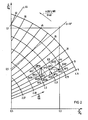
- the characteristic field of FIG. 2 shows the relationship between active power P and reactive power Q, based on the respective nominal value P N or Q N.
- the characteristic field contains the direct current Id on the HVDC link and the control angle ⁇ GR for rectifier operation of the respective converter or the extinction angle ⁇ WR for inverter operation of the respective converter.
- the characteristic field shows all permissible operating points regardless of whether the respective converter is operated as a rectifier or inverter.
- the section of the characteristic curve field shown in FIG. 2 is selected such that the operating points can preferably be derived therefrom, which for small and medium values of the rectifier control angle or inverter extinction angle up to approx. 60 ° el. Occur. If the influence of the overlap on the individual parameters of the characteristic field, which is dependent on the working point, is neglected, the characteristic lines of straight lines which result at a constant rectifier control angle or inverter extinction angle and which run through the not shown origin of the diagram.
- the rectifier control angle or inverter extinction angle would be identical to the load angle ⁇ on the network side of the respective converter.
- the mode of operation of the circuit from FIG. 1 is further explained on the basis of the transitions from an operating point AP1 to AP2 or from an operating point AP3 to AP4 shown in FIG.
- the operating point of a converter moves from AP1 to AP2 when the active power setpoint P * of the active power controller Rp is changed by the value ⁇ P12.
- the operating point AP1 ' would be set in this case by changing the direct current Id by the value ⁇ Id12. If the second controller cascade consisting of the higher-level reactive power controller Rq and the subordinate quenching angle controller R1 were then put into operation, this would compensate for the undesired reactive power control deviation ⁇ Q12 of the working point AP1 'compared to the desired working point AP2 by changing the quenching angle by the value ⁇ 12.
- the second controller cascade from the reactive power and extinguishing angle controller can compensate for a reactive power control deviation caused by the control intervention of the direct current controller by adjusting the extinguishing angle by the value ⁇ 12 so quickly that the operating point AP1 on the locus OK12 without overshoot and with a small, temporary reactive power control deviation passes into the operating point AP2.
- the transition takes place in a very similar way, e.g. from working point AP3 on the locus OK34 to working point AP4 when the reactive power setpoint changes by ⁇ Q34.
- the operating point AP3 would initially be changed due to the intervention of the controller Rq by changing the quenching angle by the value ⁇ 34 Skip operating point AP3 '.
- the undesired active power control deviation ⁇ P34 would be eliminated by changing the direct current by the value ⁇ Id34 and the working point AP3 ′ would be transferred to the actually desired working point AP4.
- the reactive power control deviation ⁇ Q34 which is the cause of the operating point transition
- the deletion angle change ⁇ 34 caused by this take an acute angle ⁇ 34 to one another due to the intervention of the subordinate controller Rq.
- the transition from AP3 to AP4 normally takes place without overshoot and with a small, temporary active power control deviation on the locus curve OK34 when both cascade controls are operated simultaneously.
- a "stability line" SG is entered as an example in FIG. 2 for this purpose. This is briefly explained using the example of the further detail of a characteristic field corresponding to FIG. 2 shown in FIG. 3. These are specifically the operating points for a converter operated as a rectifier or inverter HVDC path can be seen, which occur at medium and large rectifier control angles or inverter extinguishing angles.
- FIG. 3 shows the transitions from an operating point AP5 to AP6 or from an operating point AP7 to AP8 as examples.
- the operating point of the converter concerned moves from AP5 to AP6 when the active power setpoint is changed by ⁇ P56. If, in this case too, it is assumed that only the first cascade control from the active power and DC controllers Rp and Ri is in operation, then the working point AP5 shifts to the working point AP5 'due to the very large change in the actual DC value ⁇ Id56. This operating point differs from the actual desired working point AP6 in a large reactive power control deviation ⁇ Q56.
- the invention is based on the object, in particular, of specifying a method for regulating the converters of an HVDC link with which a sufficiently damped, stable operation of the link is possible even at medium and large rectifier control angles or inverter extinguishing angles. Furthermore, a suitable control device for carrying out the method according to the invention is to be specified.
- a pre-control variable with a corresponding sign is applied to the output signal of each of the two higher-level controllers in the first and second cascade control, which is dependent on the control variable belonging to the other of the two higher-level controllers.
- the extinguishing angle setpoint ⁇ * at the output of the higher-level voltage or reactive power controller Rq of the second cascade control in FIG. 1 is subjected to a first pilot control variable which is dependent on the deviation ⁇ P of the controlled variable P at the input of the higher-level active power controller Rq of the first cascade control.
- the first pilot control variable can in this case be applied directly to the inverter control angle ⁇ WR .
- a second pilot control variable dependent on the deviation .DELTA.U or .DELTA.Q of the controlled variable U or Q at the input of the higher-level voltage or reactive power regulator Rq of the second cascade control is applied.
- the “gain factors” belonging to the two pilot control variables take into account the operating point dependency of the desired pilot control influence of the control deviation of one of the higher-level controllers on the control signal of the other of the higher-level controllers.
- the control signal of each of the two higher-level controllers is precontrolled by means of the corresponding pilot control variable via the control deviation of the "other" of the two controllers in the sense of decoupling the two cascade controls.
- the first pilot control variable thus results from the evaluation of a currently existing active power control deviation ⁇ P with a first amplification factor. Its value corresponds to the rate of change of the inverter control angle or inverter extinction angle relative to the active power, which is present in the respective operating point of the control before the change in active power occurs and can be seen from the family of curves in FIGS.
- the first pilot control variable with a negative sign which is formed by evaluating an active power control deviation with such an operating point-dependent gain factor, must be applied to the output signal of the controller Rq.
- a pilot control of the manipulated variable of the converter UR2 operated as an inverter in particular in the event of a sudden change in the active power control deviation .DELTA.P, it can be achieved particularly advantageously that the expected due to the coupling of the two cascade controls via the controlled system and the gradients of the converter characteristic curves at the respective operating point.
- undesired deviation in the "other" controlled variable Q of the second cascade control is preset directly via the manipulated variable of the associated reactive power controller.
- the occurrence of a reactive power control deviation which is undesirably caused by the desired change in active power and which may be considerably delayed depending on the respective working point due to the controlled system itself and the dynamics of the reactive power controller may be so "anticipated" that the control, in particular in the case of medium and large, also occurs when the working points are unfavorable Rectifier control angles or inverter extinguishing angles can still be set to stable working points.
- the degree of intervention of the first step adapts control variable based on the operating point dependency of the associated gain factor itself to the prevailing conditions. This will be briefly explained using the example of FIGS. 2 and 3.
- the operating points located in this area of the characteristic field are relatively stable and the two cascade controls are therefore only slightly interconnected via the HVDC link, so that the supporting effect of the first input control variable is not actually required here at operating point transitions. Accordingly, according to the present invention, the intervention of the first pilot control variable on the control signal of the higher-level controller of the second cascade control is small, since the rate of change of the inverter control angle or inverter extinction angle, which determines the gain factor of the first pilot control variable, is also small compared to the effective power in this area of the characteristic field.
- the effect of the second input tax variable can be explained in a very similar way. According to the invention, this results from the evaluation of a currently existing voltage or reactive power control deviation .DELTA.U / .DELTA.Q with a second amplification factor. Its value corresponds to the rate of change of the HVDC direct current compared to the reactive power present in the respective working point of the control before the change in the controlled variable, as can be seen from the family of curves in FIGS. 2 and 3.
- the second pilot control variable formed by evaluating a reactive power control deviation with such an operating point-dependent gain factor must be applied to the output signal of the controller Rp with a positive sign.
- the method according to the invention thus enables suitable decoupling of the manipulated variables of the individual converters of the HVDC link such a decoupling of the associated cascade controls that any operating point in the two shown in FIGS. 2 and 3, also above the previous "stability line" SG Excerpts of the characteristic curve field of a HVDC control can be set stably.
- the input of the higher-order active power controller Rp is coupled to the output of the higher-order reactive power controller Rq via a first characteristic curve generator KG1
- the input of the higher-order reactive power controller Rq is coupled to the output of the higher-order active power regulator Rp via a second characteristic curve generator KG2.
- the first pilot control variable at the output of KG1 is designated ⁇ WR and is applied to the quenching angle setpoint ⁇ * or inverter control angle ⁇ WR formed at the output of the reactive power controller Rq, in particular via a mixing point 6 with a negative sign.
- the second pilot control variable at the output of KG 2 is designated ⁇ IdV and is applied to the direct current setpoint Id * at the output of the active power controller Rp, in particular via a mixing point 5 with a positive sign.
- An operating point change ⁇ AP1 for example caused by a sudden change in the active power setpoint P *, is processed in the embodiment of FIG. 4 by evaluating the active power control deviation ⁇ P with the first, operating point-dependent gain factor stored in the first characteristic curve generator KG1 for the first pilot control variable ⁇ WR .
- the characteristic curve generator simulates the amplification factor in the form of the sine function of the load angle ⁇ between the voltage and the current in the network in which the active power P is to be regulated, based on the product of the ideal open circuit voltage Udi and the direct current Id.
- constants can be assumed for the ideal no-load direct voltage and the direct current, the values of which preferably lie in the middle of the working range, in particular in the vicinity of the nominal operating point.
- the degree of intervention of the first pilot control variable is therefore essentially dependent on the sine function of the load angle.
- this function changes from a value slightly greater than 0 to a value when the rectifier control or inverter extinction angle changes from the smallest value at approx. 5 ° to the largest value at approx. 80 ° Value slightly less than 1 too.
- a first gain factor formed in this way according to the present invention thus makes it possible in a particularly advantageous manner that the first pilot control variable ⁇ WR is almost ineffective at small inverter control angles, and reaches its full engagement precisely at operating points above the stability line SG at medium and large inverter control angles .
- a change in the operating point ⁇ AP2 which is caused, for example, by a sudden change in the reactive power setpoint Q *, is processed by evaluating the reactive power control deviation ⁇ Q at the input of the reactive power controller Rq via the second characteristic generator KG2 to form the second pilot control variable ⁇ IdV for the actuating signal of the active power controller Rp.
- the operating point-dependent gain factor for the second pilot control variable provided via the second characteristic curve generator is simulated by the sine function of the load angle ⁇ between the voltage and the current in the network, in which the reactive power is to be regulated, preferably based on the ideal open circuit DC voltage Udi.
- the second pilot control variable is therefore essentially dependent on the sine function of the load angle dependent and achieves the greatest possible degree of intervention with medium and large inverter extinguishing angles.
- FIG 5 shows a further advantageous embodiment of the control circuit of FIG 4 according to the invention.
- the operating point changes ⁇ AP1 / ⁇ AP2 are not detected as previously by evaluating the corresponding control deviation at the input of the associated higher-level controller. Rather, the output signals Id * or ⁇ * / ⁇ WR of the respective higher-level controller are routed via additional characteristic encoders DVZ1 or DVZ2 with differentiating, delaying transmission behavior ("D-T 1" element), and as input variables to the respective characteristic encoder KG1 or KG2 made available. Since the higher-level controllers Rp and Rq generally have a proportionally integrating transmission behavior ("PI controller”), their transmission behavior is almost compensated for by the downstream D-T1 element.
- PI controller proportionally integrating transmission behavior
- this embodiment of the invention has the particular advantage that the controlled variable at the input of one of the higher-level controllers does not act directly on the control signal of the other of the higher-level controllers via the associated characteristic curve generator. Rather, the "damping" transmission behavior of the respective higher-level controller Rp or Rq is interposed.
- additional characteristic curve transmitters DVZ1 and DVZ2 additional, and possibly relatively undamped, control loops that close over the HVDC link can be avoided in this way in a particularly advantageous manner.
- FIG. 6 shows a further advantageous embodiment of the device according to the invention.
- the quotient which serves as an amplification factor, is formed from the sine function of the load angle and the ideal open circuit voltage Udi in a further characteristic curve generator KG3 as a function of the active power nominal value P * approximated in the form of a falling, straight-line characteristic.
- This embodiment has the particular advantage that the actual value of the load angle does not have to be recorded separately.
- the first pilot control variable ⁇ WR is obtained by multiplying the output signal of the characteristic curve generator KG3 by the operating point change ⁇ AP1 detected by the change in active power ⁇ P and by the reciprocal of the HVDC direct current Id by means of two multipliers M1 and M3.
- the second pilot control variable ⁇ IdV is obtained in a very similar manner by multiplying the output signal of the characteristic curve generator KG3 by a change in the operating point ⁇ AP2 detected by the reactive power change ⁇ Q by means of a further multiplier M2.
- the operating point changes ⁇ AP1 and ⁇ AP2 corresponding to the circuit of FIG 5 can be tapped at the outputs of the higher-level controller via additional D-T1 elements DVZ1 and DVZ2.
- the sine function of the load angle can be approximated by the straight line shown in FIG. 8 and designated KG3A. As has already been explained in more detail with reference to FIGS.
- the intervention of the pilot control variables for decoupling the cascade controls is required in particular in the case of medium and large inverter extinguishing angles, ie at load angles ⁇ with a value of greater than 45 °.
- the slope of the sin ⁇ approximating lines may also be chosen larger.
- Such a straight line is shown in dash-dot lines in FIG. 8 and is designated KG3B. This straight line is designed in such a way that the pilot variables ⁇ WR and ⁇ IdV at operating points which have a related reactive power value of approx. 50% and a load angle of greater than 45 °, i.e. are to the right of the vertical separation line III shown in broken lines in FIG. 8 are more involved.
- FIG. 7 shows a further advantageous embodiment of the device according to the invention.
- the operating point changes .DELTA.AP1 and .DELTA.AP2 are again detected in accordance with the circuit of FIG. 5 by evaluating the controller output variables via the additional characteristic curve transmitters DVZ1 and DVZ2 and fed to a first or second multiplier M1 or M2 to form the respective pilot control variable as shown in FIG.
- the gain-dependent gain factors required to form the pilot control variables are particularly advantageously simulated separately in two characteristic curve generators KG3 and KG4 depending on the active power setpoint P * in the form of two straight-line characteristics with in particular different negative slopes.
- the characteristic curve generator KG3 approximates the sine function of the load angle based on the ideal open circuit voltage Udi based on the characteristic curve generator KG2 and corresponding to the characteristic curve generator KG3 of the circuit of FIG.
- the characteristic curve generator KG4 simulates, based on the characteristic curve generator KG1 of the circuits in FIG. 4 and FIG. 5, the sine function of the load angle, which is based on the product of the ideal no-load direct voltage and the direct current on the HVDC link.
- the ideal open circuit voltage Udi and the HVDC direct current Id were referred to the respective nominal operating values Ud N and Id N, respectively
- a particularly advantageous "falling" straight line characteristic for the characteristic generator KG4 is shown in broken lines in FIG. 9 and is designated KG4A.
- the desired decoupling of the two cascade controls is achieved with the aid of the circuit according to the invention from FIG. 7 in a particularly advantageous manner if a falling characteristic curve with a negative slope approximately corresponding to the characteristic curve KG3A of FIG. 8 for the characteristic curve generator KG3 and a falling curve for the characteristic curve generator KG4 Characteristic curve with a negative slope approximately corresponding to the characteristic curve KG4A in FIG. 8 is selected.
Landscapes
- Engineering & Computer Science (AREA)
- Power Engineering (AREA)
- Control Of Electrical Variables (AREA)
- Inverter Devices (AREA)
- Supply And Distribution Of Alternating Current (AREA)
- Direct Current Feeding And Distribution (AREA)
Applications Claiming Priority (2)
| Application Number | Priority Date | Filing Date | Title |
|---|---|---|---|
| DE19873743997 DE3743997A1 (de) | 1987-12-23 | 1987-12-23 | Verfahren und vorrichtung zur entkopplung der wirk- und blindleistungsregelung bei einer zwei netze verbindenden hochspannungs-gleichstrom-uebertragungsstrecke |
| DE3743997 | 1987-12-23 |
Publications (2)
| Publication Number | Publication Date |
|---|---|
| EP0321823A1 true EP0321823A1 (fr) | 1989-06-28 |
| EP0321823B1 EP0321823B1 (fr) | 1992-04-01 |
Family
ID=6343532
Family Applications (1)
| Application Number | Title | Priority Date | Filing Date |
|---|---|---|---|
| EP88120742A Expired - Lifetime EP0321823B1 (fr) | 1987-12-23 | 1988-12-12 | Méthode et dispositif pour le découplage de la puissance active et réactive dans une liaison de deux réseaux haute tension en courant continu |
Country Status (5)
| Country | Link |
|---|---|
| US (1) | US4888674A (fr) |
| EP (1) | EP0321823B1 (fr) |
| JP (1) | JPH01209928A (fr) |
| CA (1) | CA1313537C (fr) |
| DE (2) | DE3743997A1 (fr) |
Cited By (4)
| Publication number | Priority date | Publication date | Assignee | Title |
|---|---|---|---|---|
| WO1992022118A1 (fr) * | 1991-05-27 | 1992-12-10 | Siemens Aktiengesellschaft | Procede de circuit pour la transmission de courant continu |
| EP0554804A1 (fr) * | 1992-01-30 | 1993-08-11 | Hitachi, Ltd. | Dispositif de réglage pour un système de transmission en courant continu de haute tension |
| WO1996024978A1 (fr) * | 1995-02-10 | 1996-08-15 | Asea Brown Boveri Ab | Installation de transport d'energie electrique par courant continu haute tension |
| WO2019101307A1 (fr) * | 2017-11-22 | 2019-05-31 | Siemens Aktiengesellschaft | Transfert d'énergie par une voie de transmission sous haute tension continue bipolaire |
Families Citing this family (8)
| Publication number | Priority date | Publication date | Assignee | Title |
|---|---|---|---|---|
| DE4343899A1 (de) * | 1993-12-22 | 1995-06-29 | Abb Management Ag | Regelungsverfahren für einen Gleichstromlichtbogenofen |
| DE4420600C1 (de) * | 1994-06-13 | 1995-11-16 | Siemens Ag | Verfahren und Anordnung zur Gleichstromübertragung |
| SE506199C2 (sv) * | 1996-03-26 | 1997-11-17 | Asea Brown Boveri | Förfarande och anordning för bestämning av kortslutningseffekten i ett elektriskt växelströmskraftnät som är anslutet till en högspänd likströmsöverföring |
| US6631080B2 (en) | 2001-06-06 | 2003-10-07 | Hybrid Power Generation Systems Llc | Systems and methods for boosting DC link voltage in turbine generators |
| WO2011101027A1 (fr) * | 2010-02-17 | 2011-08-25 | Areva T&D Uk Ltd | Commande de puissance réactive pour une liaison cc à haute tension |
| CN104104221B (zh) * | 2013-04-11 | 2017-05-17 | 通用电气公司 | 具有有功无功功率解耦补偿机制的能量转换系统和方法 |
| DE102013214693A1 (de) * | 2013-07-26 | 2015-01-29 | Siemens Aktiengesellschaft | Anordnung zur Kompensation von Blindleistung und Wirkleistung in einem Hochspannungsnetz |
| WO2015196193A1 (fr) | 2014-06-20 | 2015-12-23 | General Electric Company | Système et procédé permettant une commande de puissance pour une station de charge à stockage d'énergie |
Citations (5)
| Publication number | Priority date | Publication date | Assignee | Title |
|---|---|---|---|---|
| FR2073139A5 (fr) * | 1969-12-11 | 1971-09-24 | Bbc Brown Boveri & Cie | Procede pour le reglage du facteur de puissance ou de la tension dans un reseau triphase,a l'aide d'un"couplage court"en courant continu haute tension |
| US3949291A (en) * | 1969-12-11 | 1976-04-06 | Bbc Aktiengesellschaft Brown, Boveri & Cie. | Short HVDC transmission system with power factor control |
| EP0067978A2 (fr) * | 1981-06-10 | 1982-12-29 | Siemens Aktiengesellschaft | Procédé et dispositif pour la régulation de la puissance réactive du réseau dans un transport d'énergie en courant continu à haute tension |
| EP0156396A2 (fr) * | 1984-03-29 | 1985-10-02 | Kabushiki Kaisha Toshiba | Appareil pour la régulation d'un convertisseur d'énergie et procédé pour la régulation d'un convertisseur d'énergie |
| EP0237032A2 (fr) * | 1986-03-14 | 1987-09-16 | Kabushiki Kaisha Toshiba | Système de transmission à courant continu |
Family Cites Families (5)
| Publication number | Priority date | Publication date | Assignee | Title |
|---|---|---|---|---|
| JPS58112423A (ja) * | 1981-12-26 | 1983-07-04 | 株式会社東芝 | 電力変換設備の制御方式 |
| JPS58148625A (ja) * | 1982-02-26 | 1983-09-03 | 株式会社東芝 | 変換器の制御装置 |
| DE3326947A1 (de) * | 1983-07-22 | 1985-02-07 | Licentia Patent-Verwaltungs-Gmbh, 6000 Frankfurt | Verfahren und schaltungsanordnung zum betrieb einer hochspannungs-gleichstrom-verbindung zwischen zwei wechselspannungsnetzen |
| DE3431979A1 (de) * | 1984-08-30 | 1986-03-06 | Siemens AG, 1000 Berlin und 8000 München | Verfahren und vorrichtung zum unterdruecken von resonanzerscheinungen im wechselrichterseitigen wechselspannungsnetz einer hochspannungsgleichstromuebertragungsanlage |
| ATE44337T1 (de) * | 1985-03-27 | 1989-07-15 | Siemens Ag | Verfahren und vorrichtung zum betrieb einer hgue- kurzkupplung bei netzfehlern. |
-
1987
- 1987-12-23 DE DE19873743997 patent/DE3743997A1/de not_active Withdrawn
-
1988
- 1988-12-12 DE DE8888120742T patent/DE3869754D1/de not_active Expired - Fee Related
- 1988-12-12 EP EP88120742A patent/EP0321823B1/fr not_active Expired - Lifetime
- 1988-12-20 JP JP63323192A patent/JPH01209928A/ja active Pending
- 1988-12-21 CA CA000586551A patent/CA1313537C/fr not_active Expired - Fee Related
- 1988-12-21 US US07/288,282 patent/US4888674A/en not_active Expired - Fee Related
Patent Citations (5)
| Publication number | Priority date | Publication date | Assignee | Title |
|---|---|---|---|---|
| FR2073139A5 (fr) * | 1969-12-11 | 1971-09-24 | Bbc Brown Boveri & Cie | Procede pour le reglage du facteur de puissance ou de la tension dans un reseau triphase,a l'aide d'un"couplage court"en courant continu haute tension |
| US3949291A (en) * | 1969-12-11 | 1976-04-06 | Bbc Aktiengesellschaft Brown, Boveri & Cie. | Short HVDC transmission system with power factor control |
| EP0067978A2 (fr) * | 1981-06-10 | 1982-12-29 | Siemens Aktiengesellschaft | Procédé et dispositif pour la régulation de la puissance réactive du réseau dans un transport d'énergie en courant continu à haute tension |
| EP0156396A2 (fr) * | 1984-03-29 | 1985-10-02 | Kabushiki Kaisha Toshiba | Appareil pour la régulation d'un convertisseur d'énergie et procédé pour la régulation d'un convertisseur d'énergie |
| EP0237032A2 (fr) * | 1986-03-14 | 1987-09-16 | Kabushiki Kaisha Toshiba | Système de transmission à courant continu |
Cited By (6)
| Publication number | Priority date | Publication date | Assignee | Title |
|---|---|---|---|---|
| WO1992022118A1 (fr) * | 1991-05-27 | 1992-12-10 | Siemens Aktiengesellschaft | Procede de circuit pour la transmission de courant continu |
| US5479332A (en) * | 1991-05-27 | 1995-12-26 | Siemens Aktiengesellschaft | System avoiding regulator detachments in quasi-steady operation of ADC power transmission line |
| EP0554804A1 (fr) * | 1992-01-30 | 1993-08-11 | Hitachi, Ltd. | Dispositif de réglage pour un système de transmission en courant continu de haute tension |
| WO1996024978A1 (fr) * | 1995-02-10 | 1996-08-15 | Asea Brown Boveri Ab | Installation de transport d'energie electrique par courant continu haute tension |
| WO2019101307A1 (fr) * | 2017-11-22 | 2019-05-31 | Siemens Aktiengesellschaft | Transfert d'énergie par une voie de transmission sous haute tension continue bipolaire |
| US10938213B2 (en) | 2017-11-22 | 2021-03-02 | Siemens Aktiengesellschaft | Power transmission via a bipolar high-voltage DC transmission link |
Also Published As
| Publication number | Publication date |
|---|---|
| CA1313537C (fr) | 1993-02-09 |
| JPH01209928A (ja) | 1989-08-23 |
| DE3869754D1 (de) | 1992-05-07 |
| DE3743997A1 (de) | 1988-11-17 |
| EP0321823B1 (fr) | 1992-04-01 |
| US4888674A (en) | 1989-12-19 |
Similar Documents
| Publication | Publication Date | Title |
|---|---|---|
| EP0321823B1 (fr) | Méthode et dispositif pour le découplage de la puissance active et réactive dans une liaison de deux réseaux haute tension en courant continu | |
| EP1927186B1 (fr) | Procede de reglage pour une transmission de courant continu a l'aide de plusieurs convertisseurs de courant | |
| DE3122988A1 (de) | Blindleistungsgenerator | |
| EP0169488B1 (fr) | Circuit transformateur | |
| DE3117971A1 (de) | Regelung zum leistungsoptimalen anpassen des luftspaltes von elektromagnetischen schwebefahrzeugen | |
| EP0208088B1 (fr) | Dispositif pur l'obtention d'un système de tensions triphasées avec conducteur neutre chargeable | |
| DE2834564C2 (de) | Hochspannungsgleichstromübertragungsanlage | |
| EP0103133A1 (fr) | Dispositif de réglage pour convertisseurs de courant | |
| EP0571643B1 (fr) | Procédé et dispositif de commande symétrique d'une installation de compensation série | |
| DE2022621C3 (de) | Steuerschaltung für einen statischen Wechselrichter | |
| DE2538493C3 (de) | Gegen Überstrom geschützte Hochspannungsgleichstromübertragungsanlage | |
| WO1994022211A1 (fr) | Procede et dispositifs de regulation utiles pour la transmission de courant continu | |
| EP1053588B1 (fr) | Procedes pour etablir des instructions de reglage pour redresseurs | |
| WO1994022199A1 (fr) | Procede et agencement de regulation, ainsi que dispositif de regulation, utiles pour la transmission de courant continu | |
| EP0782783A1 (fr) | Procede de regulation d'un regulateur a quatre quadrants utile comme convertisseur de puissance reseau | |
| EP0586369B1 (fr) | Procede de circuit pour la transmission de courant continu | |
| DE102020126925B4 (de) | Regler | |
| DE4420600C1 (de) | Verfahren und Anordnung zur Gleichstromübertragung | |
| EP0579240B1 (fr) | Méthode et dispositif pour réguler le potentiel milieu de la connection série, cÔté continu, de deux onduleurs de traction deux-points | |
| DE19611418C1 (de) | Verfahren zur Vorgabe einer vorbestimmten Ausgangsimpedanz eines Ausgangskreises eines Wechselrichters | |
| WO2024033342A1 (fr) | Onduleur de réglage de tension et installation de production d'énergie | |
| EP3447602A1 (fr) | Procédé et dispositif de commande de réglage de la tension d'un système de transformateur | |
| DE2429235A1 (de) | Stromrichterstation fuer hochspannungsgleichstromuebertragungsanlage | |
| DE2818933A1 (de) | Regelverfahren fuer eine asynchronmaschine sowie schaltungsanordnung zur durchfuehrung des verfahrens | |
| EP0171617A1 (fr) | Méthode et dispositif pour l'exploitation d'un convertisseur indirect avec limitation de la montée de courant |
Legal Events
| Date | Code | Title | Description |
|---|---|---|---|
| PUAI | Public reference made under article 153(3) epc to a published international application that has entered the european phase |
Free format text: ORIGINAL CODE: 0009012 |
|
| AK | Designated contracting states |
Kind code of ref document: A1 Designated state(s): CH DE FR GB LI SE |
|
| 17P | Request for examination filed |
Effective date: 19890726 |
|
| 17Q | First examination report despatched |
Effective date: 19910904 |
|
| GRAA | (expected) grant |
Free format text: ORIGINAL CODE: 0009210 |
|
| AK | Designated contracting states |
Kind code of ref document: B1 Designated state(s): CH DE FR GB LI SE |
|
| REF | Corresponds to: |
Ref document number: 3869754 Country of ref document: DE Date of ref document: 19920507 |
|
| ET | Fr: translation filed | ||
| GBT | Gb: translation of ep patent filed (gb section 77(6)(a)/1977) | ||
| PGFP | Annual fee paid to national office [announced via postgrant information from national office to epo] |
Ref country code: FR Payment date: 19921221 Year of fee payment: 5 |
|
| PG25 | Lapsed in a contracting state [announced via postgrant information from national office to epo] |
Ref country code: LI Effective date: 19921231 Ref country code: CH Effective date: 19921231 |
|
| PLBE | No opposition filed within time limit |
Free format text: ORIGINAL CODE: 0009261 |
|
| STAA | Information on the status of an ep patent application or granted ep patent |
Free format text: STATUS: NO OPPOSITION FILED WITHIN TIME LIMIT |
|
| 26N | No opposition filed | ||
| REG | Reference to a national code |
Ref country code: CH Ref legal event code: PL |
|
| PG25 | Lapsed in a contracting state [announced via postgrant information from national office to epo] |
Ref country code: FR Effective date: 19940831 |
|
| REG | Reference to a national code |
Ref country code: FR Ref legal event code: ST |
|
| EAL | Se: european patent in force in sweden |
Ref document number: 88120742.7 |
|
| PGFP | Annual fee paid to national office [announced via postgrant information from national office to epo] |
Ref country code: GB Payment date: 19981210 Year of fee payment: 11 |
|
| PGFP | Annual fee paid to national office [announced via postgrant information from national office to epo] |
Ref country code: SE Payment date: 19981222 Year of fee payment: 11 |
|
| PGFP | Annual fee paid to national office [announced via postgrant information from national office to epo] |
Ref country code: DE Payment date: 19990219 Year of fee payment: 11 |
|
| PG25 | Lapsed in a contracting state [announced via postgrant information from national office to epo] |
Ref country code: GB Free format text: LAPSE BECAUSE OF NON-PAYMENT OF DUE FEES Effective date: 19991212 |
|
| PG25 | Lapsed in a contracting state [announced via postgrant information from national office to epo] |
Ref country code: SE Free format text: LAPSE BECAUSE OF NON-PAYMENT OF DUE FEES Effective date: 19991213 |
|
| GBPC | Gb: european patent ceased through non-payment of renewal fee |
Effective date: 19991212 |
|
| EUG | Se: european patent has lapsed |
Ref document number: 88120742.7 |
|
| PG25 | Lapsed in a contracting state [announced via postgrant information from national office to epo] |
Ref country code: DE Free format text: LAPSE BECAUSE OF NON-PAYMENT OF DUE FEES Effective date: 20001003 |