EP0321823A1 - Method and device for disconnecting the active and reactive power supply of a two-network high-voltage direct-current power transmission link - Google Patents
Method and device for disconnecting the active and reactive power supply of a two-network high-voltage direct-current power transmission link Download PDFInfo
- Publication number
- EP0321823A1 EP0321823A1 EP88120742A EP88120742A EP0321823A1 EP 0321823 A1 EP0321823 A1 EP 0321823A1 EP 88120742 A EP88120742 A EP 88120742A EP 88120742 A EP88120742 A EP 88120742A EP 0321823 A1 EP0321823 A1 EP 0321823A1
- Authority
- EP
- European Patent Office
- Prior art keywords
- voltage
- control
- controller
- reactive power
- level
- Prior art date
- Legal status (The legal status is an assumption and is not a legal conclusion. Google has not performed a legal analysis and makes no representation as to the accuracy of the status listed.)
- Granted
Links
Images


Classifications
-
- H—ELECTRICITY
- H02—GENERATION; CONVERSION OR DISTRIBUTION OF ELECTRIC POWER
- H02J—CIRCUIT ARRANGEMENTS OR SYSTEMS FOR SUPPLYING OR DISTRIBUTING ELECTRIC POWER; SYSTEMS FOR STORING ELECTRIC ENERGY
- H02J3/00—Circuit arrangements for ac mains or ac distribution networks
- H02J3/36—Arrangements for transfer of electric power between ac networks via a high-tension dc link
-
- Y—GENERAL TAGGING OF NEW TECHNOLOGICAL DEVELOPMENTS; GENERAL TAGGING OF CROSS-SECTIONAL TECHNOLOGIES SPANNING OVER SEVERAL SECTIONS OF THE IPC; TECHNICAL SUBJECTS COVERED BY FORMER USPC CROSS-REFERENCE ART COLLECTIONS [XRACs] AND DIGESTS
- Y02—TECHNOLOGIES OR APPLICATIONS FOR MITIGATION OR ADAPTATION AGAINST CLIMATE CHANGE
- Y02E—REDUCTION OF GREENHOUSE GAS [GHG] EMISSIONS, RELATED TO ENERGY GENERATION, TRANSMISSION OR DISTRIBUTION
- Y02E60/00—Enabling technologies; Technologies with a potential or indirect contribution to GHG emissions mitigation
- Y02E60/60—Arrangements for transfer of electric power between AC networks or generators via a high voltage DC link [HVCD]
Definitions
- the invention relates to a method for regulating the active and reactive power transmission between two electrical networks, which are connected via a high-voltage direct-current transmission link ("HVDC" link), in particular as a short coupling, according to the preamble of claim 1.
- the invention further relates to a control device for active and reactive power transmission.
- HVDC link shows a known control structure for a high-voltage direct current transmission link ("HVDC link").
- Two, in particular three-phase power supply networks A and B are each coupled to the ends of an HVDC link via a controllable converter UR1 and UR2.
- the electrical parameters of the line are provided with the reference symbols Id for the direct current and Ud for the direct voltage.
- a smoothing inductance Ld for damping harmonics in the HVDC link is shown as an example.
- one of the two inverters UR1, UR2 works as a rectifier and the other as an inverter. 1 it is assumed that the converter UR1 works in rectifier mode and the converter UR2 works in inverter mode.
- Two cascade controls are used to control the active power P and the line voltage U or the reactive power Q in one of the two networks. These each act on one of the two inverters and are shown in FIG. 1 on the left side of the vertical dashed line marked II.
- the subordinate or higher-level controllers of the respective cascade control are shown on the right or left of a further dashed line marked I.
- the control deviation ⁇ P formed by means of a mixing point 1 from an active power setpoint P * and an active power actual value P is fed to a superordinate active power controller Rp. Its output signal serves as setpoint Id * for the value of the direct current on the HVDC link.
- the associated control deviation is formed by means of a second mixing point 2 by comparison with the actual DC value Id and fed to a subordinate direct current controller Ri.
- the second cascade control acts on the converter UR2 operated as an inverter in the example in FIG.
- a higher-level controller Rq can serve both as a controller for the line voltage U and as a controller for the reactive power Q in one of the two networks.
- the voltage or reactive power control deviation .DELTA.U / .DELTA.Q for this controller is formed by comparing the corresponding setpoint values U * / Q * with the associated actual values U / Q in a third mixing point 3.
- the output signal of this higher-level controller Rq serves as setpoint value ⁇ * for the extinction angle of the inverter UR2.
- the associated control deviation ⁇ is formed by comparison with the extinction angle actual value ⁇ in a fourth mixing point 4 and fed to a subordinate extinction angle regulator R1.
- the inverter influences the DC voltage Ud on the HVDC link in a suitable manner by magnitude and sign.
- the subordinate extinguishing angle regulator R1 can also be omitted.
- the higher-level voltage or reactive power controller Rq directly specifies the control angle ⁇ WR for the UR2 inverter.
- the overlap angle u considered advance angle and the extinction angle ⁇ are used directly.
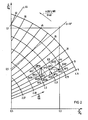
- the characteristic field of FIG. 2 shows the relationship between active power P and reactive power Q, based on the respective nominal value P N or Q N.
- the characteristic field contains the direct current Id on the HVDC link and the control angle ⁇ GR for rectifier operation of the respective converter or the extinction angle ⁇ WR for inverter operation of the respective converter.
- the characteristic field shows all permissible operating points regardless of whether the respective converter is operated as a rectifier or inverter.
- the section of the characteristic curve field shown in FIG. 2 is selected such that the operating points can preferably be derived therefrom, which for small and medium values of the rectifier control angle or inverter extinction angle up to approx. 60 ° el. Occur. If the influence of the overlap on the individual parameters of the characteristic field, which is dependent on the working point, is neglected, the characteristic lines of straight lines which result at a constant rectifier control angle or inverter extinction angle and which run through the not shown origin of the diagram.
- the rectifier control angle or inverter extinction angle would be identical to the load angle ⁇ on the network side of the respective converter.
- the mode of operation of the circuit from FIG. 1 is further explained on the basis of the transitions from an operating point AP1 to AP2 or from an operating point AP3 to AP4 shown in FIG.
- the operating point of a converter moves from AP1 to AP2 when the active power setpoint P * of the active power controller Rp is changed by the value ⁇ P12.
- the operating point AP1 ' would be set in this case by changing the direct current Id by the value ⁇ Id12. If the second controller cascade consisting of the higher-level reactive power controller Rq and the subordinate quenching angle controller R1 were then put into operation, this would compensate for the undesired reactive power control deviation ⁇ Q12 of the working point AP1 'compared to the desired working point AP2 by changing the quenching angle by the value ⁇ 12.
- the second controller cascade from the reactive power and extinguishing angle controller can compensate for a reactive power control deviation caused by the control intervention of the direct current controller by adjusting the extinguishing angle by the value ⁇ 12 so quickly that the operating point AP1 on the locus OK12 without overshoot and with a small, temporary reactive power control deviation passes into the operating point AP2.
- the transition takes place in a very similar way, e.g. from working point AP3 on the locus OK34 to working point AP4 when the reactive power setpoint changes by ⁇ Q34.
- the operating point AP3 would initially be changed due to the intervention of the controller Rq by changing the quenching angle by the value ⁇ 34 Skip operating point AP3 '.
- the undesired active power control deviation ⁇ P34 would be eliminated by changing the direct current by the value ⁇ Id34 and the working point AP3 ′ would be transferred to the actually desired working point AP4.
- the reactive power control deviation ⁇ Q34 which is the cause of the operating point transition
- the deletion angle change ⁇ 34 caused by this take an acute angle ⁇ 34 to one another due to the intervention of the subordinate controller Rq.
- the transition from AP3 to AP4 normally takes place without overshoot and with a small, temporary active power control deviation on the locus curve OK34 when both cascade controls are operated simultaneously.
- a "stability line" SG is entered as an example in FIG. 2 for this purpose. This is briefly explained using the example of the further detail of a characteristic field corresponding to FIG. 2 shown in FIG. 3. These are specifically the operating points for a converter operated as a rectifier or inverter HVDC path can be seen, which occur at medium and large rectifier control angles or inverter extinguishing angles.
- FIG. 3 shows the transitions from an operating point AP5 to AP6 or from an operating point AP7 to AP8 as examples.
- the operating point of the converter concerned moves from AP5 to AP6 when the active power setpoint is changed by ⁇ P56. If, in this case too, it is assumed that only the first cascade control from the active power and DC controllers Rp and Ri is in operation, then the working point AP5 shifts to the working point AP5 'due to the very large change in the actual DC value ⁇ Id56. This operating point differs from the actual desired working point AP6 in a large reactive power control deviation ⁇ Q56.
- the invention is based on the object, in particular, of specifying a method for regulating the converters of an HVDC link with which a sufficiently damped, stable operation of the link is possible even at medium and large rectifier control angles or inverter extinguishing angles. Furthermore, a suitable control device for carrying out the method according to the invention is to be specified.
- a pre-control variable with a corresponding sign is applied to the output signal of each of the two higher-level controllers in the first and second cascade control, which is dependent on the control variable belonging to the other of the two higher-level controllers.
- the extinguishing angle setpoint ⁇ * at the output of the higher-level voltage or reactive power controller Rq of the second cascade control in FIG. 1 is subjected to a first pilot control variable which is dependent on the deviation ⁇ P of the controlled variable P at the input of the higher-level active power controller Rq of the first cascade control.
- the first pilot control variable can in this case be applied directly to the inverter control angle ⁇ WR .
- a second pilot control variable dependent on the deviation .DELTA.U or .DELTA.Q of the controlled variable U or Q at the input of the higher-level voltage or reactive power regulator Rq of the second cascade control is applied.
- the “gain factors” belonging to the two pilot control variables take into account the operating point dependency of the desired pilot control influence of the control deviation of one of the higher-level controllers on the control signal of the other of the higher-level controllers.
- the control signal of each of the two higher-level controllers is precontrolled by means of the corresponding pilot control variable via the control deviation of the "other" of the two controllers in the sense of decoupling the two cascade controls.
- the first pilot control variable thus results from the evaluation of a currently existing active power control deviation ⁇ P with a first amplification factor. Its value corresponds to the rate of change of the inverter control angle or inverter extinction angle relative to the active power, which is present in the respective operating point of the control before the change in active power occurs and can be seen from the family of curves in FIGS.
- the first pilot control variable with a negative sign which is formed by evaluating an active power control deviation with such an operating point-dependent gain factor, must be applied to the output signal of the controller Rq.
- a pilot control of the manipulated variable of the converter UR2 operated as an inverter in particular in the event of a sudden change in the active power control deviation .DELTA.P, it can be achieved particularly advantageously that the expected due to the coupling of the two cascade controls via the controlled system and the gradients of the converter characteristic curves at the respective operating point.
- undesired deviation in the "other" controlled variable Q of the second cascade control is preset directly via the manipulated variable of the associated reactive power controller.
- the occurrence of a reactive power control deviation which is undesirably caused by the desired change in active power and which may be considerably delayed depending on the respective working point due to the controlled system itself and the dynamics of the reactive power controller may be so "anticipated" that the control, in particular in the case of medium and large, also occurs when the working points are unfavorable Rectifier control angles or inverter extinguishing angles can still be set to stable working points.
- the degree of intervention of the first step adapts control variable based on the operating point dependency of the associated gain factor itself to the prevailing conditions. This will be briefly explained using the example of FIGS. 2 and 3.
- the operating points located in this area of the characteristic field are relatively stable and the two cascade controls are therefore only slightly interconnected via the HVDC link, so that the supporting effect of the first input control variable is not actually required here at operating point transitions. Accordingly, according to the present invention, the intervention of the first pilot control variable on the control signal of the higher-level controller of the second cascade control is small, since the rate of change of the inverter control angle or inverter extinction angle, which determines the gain factor of the first pilot control variable, is also small compared to the effective power in this area of the characteristic field.
- the effect of the second input tax variable can be explained in a very similar way. According to the invention, this results from the evaluation of a currently existing voltage or reactive power control deviation .DELTA.U / .DELTA.Q with a second amplification factor. Its value corresponds to the rate of change of the HVDC direct current compared to the reactive power present in the respective working point of the control before the change in the controlled variable, as can be seen from the family of curves in FIGS. 2 and 3.
- the second pilot control variable formed by evaluating a reactive power control deviation with such an operating point-dependent gain factor must be applied to the output signal of the controller Rp with a positive sign.
- the method according to the invention thus enables suitable decoupling of the manipulated variables of the individual converters of the HVDC link such a decoupling of the associated cascade controls that any operating point in the two shown in FIGS. 2 and 3, also above the previous "stability line" SG Excerpts of the characteristic curve field of a HVDC control can be set stably.
- the input of the higher-order active power controller Rp is coupled to the output of the higher-order reactive power controller Rq via a first characteristic curve generator KG1
- the input of the higher-order reactive power controller Rq is coupled to the output of the higher-order active power regulator Rp via a second characteristic curve generator KG2.
- the first pilot control variable at the output of KG1 is designated ⁇ WR and is applied to the quenching angle setpoint ⁇ * or inverter control angle ⁇ WR formed at the output of the reactive power controller Rq, in particular via a mixing point 6 with a negative sign.
- the second pilot control variable at the output of KG 2 is designated ⁇ IdV and is applied to the direct current setpoint Id * at the output of the active power controller Rp, in particular via a mixing point 5 with a positive sign.
- An operating point change ⁇ AP1 for example caused by a sudden change in the active power setpoint P *, is processed in the embodiment of FIG. 4 by evaluating the active power control deviation ⁇ P with the first, operating point-dependent gain factor stored in the first characteristic curve generator KG1 for the first pilot control variable ⁇ WR .
- the characteristic curve generator simulates the amplification factor in the form of the sine function of the load angle ⁇ between the voltage and the current in the network in which the active power P is to be regulated, based on the product of the ideal open circuit voltage Udi and the direct current Id.
- constants can be assumed for the ideal no-load direct voltage and the direct current, the values of which preferably lie in the middle of the working range, in particular in the vicinity of the nominal operating point.
- the degree of intervention of the first pilot control variable is therefore essentially dependent on the sine function of the load angle.
- this function changes from a value slightly greater than 0 to a value when the rectifier control or inverter extinction angle changes from the smallest value at approx. 5 ° to the largest value at approx. 80 ° Value slightly less than 1 too.
- a first gain factor formed in this way according to the present invention thus makes it possible in a particularly advantageous manner that the first pilot control variable ⁇ WR is almost ineffective at small inverter control angles, and reaches its full engagement precisely at operating points above the stability line SG at medium and large inverter control angles .
- a change in the operating point ⁇ AP2 which is caused, for example, by a sudden change in the reactive power setpoint Q *, is processed by evaluating the reactive power control deviation ⁇ Q at the input of the reactive power controller Rq via the second characteristic generator KG2 to form the second pilot control variable ⁇ IdV for the actuating signal of the active power controller Rp.
- the operating point-dependent gain factor for the second pilot control variable provided via the second characteristic curve generator is simulated by the sine function of the load angle ⁇ between the voltage and the current in the network, in which the reactive power is to be regulated, preferably based on the ideal open circuit DC voltage Udi.
- the second pilot control variable is therefore essentially dependent on the sine function of the load angle dependent and achieves the greatest possible degree of intervention with medium and large inverter extinguishing angles.
- FIG 5 shows a further advantageous embodiment of the control circuit of FIG 4 according to the invention.
- the operating point changes ⁇ AP1 / ⁇ AP2 are not detected as previously by evaluating the corresponding control deviation at the input of the associated higher-level controller. Rather, the output signals Id * or ⁇ * / ⁇ WR of the respective higher-level controller are routed via additional characteristic encoders DVZ1 or DVZ2 with differentiating, delaying transmission behavior ("D-T 1" element), and as input variables to the respective characteristic encoder KG1 or KG2 made available. Since the higher-level controllers Rp and Rq generally have a proportionally integrating transmission behavior ("PI controller”), their transmission behavior is almost compensated for by the downstream D-T1 element.
- PI controller proportionally integrating transmission behavior
- this embodiment of the invention has the particular advantage that the controlled variable at the input of one of the higher-level controllers does not act directly on the control signal of the other of the higher-level controllers via the associated characteristic curve generator. Rather, the "damping" transmission behavior of the respective higher-level controller Rp or Rq is interposed.
- additional characteristic curve transmitters DVZ1 and DVZ2 additional, and possibly relatively undamped, control loops that close over the HVDC link can be avoided in this way in a particularly advantageous manner.
- FIG. 6 shows a further advantageous embodiment of the device according to the invention.
- the quotient which serves as an amplification factor, is formed from the sine function of the load angle and the ideal open circuit voltage Udi in a further characteristic curve generator KG3 as a function of the active power nominal value P * approximated in the form of a falling, straight-line characteristic.
- This embodiment has the particular advantage that the actual value of the load angle does not have to be recorded separately.
- the first pilot control variable ⁇ WR is obtained by multiplying the output signal of the characteristic curve generator KG3 by the operating point change ⁇ AP1 detected by the change in active power ⁇ P and by the reciprocal of the HVDC direct current Id by means of two multipliers M1 and M3.
- the second pilot control variable ⁇ IdV is obtained in a very similar manner by multiplying the output signal of the characteristic curve generator KG3 by a change in the operating point ⁇ AP2 detected by the reactive power change ⁇ Q by means of a further multiplier M2.
- the operating point changes ⁇ AP1 and ⁇ AP2 corresponding to the circuit of FIG 5 can be tapped at the outputs of the higher-level controller via additional D-T1 elements DVZ1 and DVZ2.
- the sine function of the load angle can be approximated by the straight line shown in FIG. 8 and designated KG3A. As has already been explained in more detail with reference to FIGS.
- the intervention of the pilot control variables for decoupling the cascade controls is required in particular in the case of medium and large inverter extinguishing angles, ie at load angles ⁇ with a value of greater than 45 °.
- the slope of the sin ⁇ approximating lines may also be chosen larger.
- Such a straight line is shown in dash-dot lines in FIG. 8 and is designated KG3B. This straight line is designed in such a way that the pilot variables ⁇ WR and ⁇ IdV at operating points which have a related reactive power value of approx. 50% and a load angle of greater than 45 °, i.e. are to the right of the vertical separation line III shown in broken lines in FIG. 8 are more involved.
- FIG. 7 shows a further advantageous embodiment of the device according to the invention.
- the operating point changes .DELTA.AP1 and .DELTA.AP2 are again detected in accordance with the circuit of FIG. 5 by evaluating the controller output variables via the additional characteristic curve transmitters DVZ1 and DVZ2 and fed to a first or second multiplier M1 or M2 to form the respective pilot control variable as shown in FIG.
- the gain-dependent gain factors required to form the pilot control variables are particularly advantageously simulated separately in two characteristic curve generators KG3 and KG4 depending on the active power setpoint P * in the form of two straight-line characteristics with in particular different negative slopes.
- the characteristic curve generator KG3 approximates the sine function of the load angle based on the ideal open circuit voltage Udi based on the characteristic curve generator KG2 and corresponding to the characteristic curve generator KG3 of the circuit of FIG.
- the characteristic curve generator KG4 simulates, based on the characteristic curve generator KG1 of the circuits in FIG. 4 and FIG. 5, the sine function of the load angle, which is based on the product of the ideal no-load direct voltage and the direct current on the HVDC link.
- the ideal open circuit voltage Udi and the HVDC direct current Id were referred to the respective nominal operating values Ud N and Id N, respectively
- a particularly advantageous "falling" straight line characteristic for the characteristic generator KG4 is shown in broken lines in FIG. 9 and is designated KG4A.
- the desired decoupling of the two cascade controls is achieved with the aid of the circuit according to the invention from FIG. 7 in a particularly advantageous manner if a falling characteristic curve with a negative slope approximately corresponding to the characteristic curve KG3A of FIG. 8 for the characteristic curve generator KG3 and a falling curve for the characteristic curve generator KG4 Characteristic curve with a negative slope approximately corresponding to the characteristic curve KG4A in FIG. 8 is selected.
Abstract
Bei einer Hochspannungs-Gleichstrom-Übertragungsanlage ("HGÜ- Anlage") wird einer der Umrichter als ein Gleichrichter (UR1) und der andere als ein Wechselrichter (UR2) betrieben. Eine erste Kaskadenregelung zur Vorgabe des Gleichrichtersteuerwinkels (αGR) besteht aus einem übergeordneten Wirkleistungsregler (Rp) und einem unterlagerten Gleichstromregler (Ri). Eine zweite Kaskadenregelung zur Vorgabe des Wechselrichtersteuerwinkels (αWR) besteht aus einem übergeordneten Spannungs- oder Blindleistungsregler (Rq) und bevorzugt einem unterlagerten Löschwinkelregler (R1). Erfindungsgemäß wird das Stellsignal ( γ*,Id*) eines jeden der beiden übergeordneten Regler bevorzugt in Abhängigkeit der Regelabweichung (δP, ΔU/ΔQ) des jeweils anderen der beiden übergeordneten Regler über eine erste bzw. zweite Vorsteuergröße (ΔαWR, ΔIdV) zur Entkopplung der Kaskadenregelungen vorgesteuert. Die Verstärkungsfaktoren für die Vorsteuergrößen sind so arbeitspunktabhängig, daß insbesondere bei kleinen Steuerwinkeln ein geringer, dagegen bei großen Steuerwinkeln ein starker Eingriff der Vorsteuergrößen bewirkt wird.In a high-voltage direct current transmission system ("HVDC system"), one of the converters is operated as a rectifier (UR1) and the other as an inverter (UR2). A first cascade control for specifying the rectifier control angle (αGR) consists of a higher-level active power controller (Rp) and a lower-level DC controller (Ri). A second cascade control for specifying the inverter control angle (αWR) consists of a higher-level voltage or reactive power controller (Rq) and preferably a subordinate quenching angle controller (R1). According to the invention, the control signal (γ *, Id *) of each of the two higher-level controllers is preferably used as a function of the control deviation (δP, ΔU / ΔQ) of the other of the two higher-level controllers via a first or second pilot control variable (ΔαWR, ΔIdV) for decoupling of the cascade controls. The amplification factors for the pilot control variables are so dependent on the operating point that a small intervention of the pilot control variables is effected, in particular at small control angles, but a strong intervention at large control angles.
Description
Die Erfindung betrifft ein Verfahren zur Regelung der Wirk- und Blindleistungsübertragung zwischen zwei elektrischen Netzen, welche über eine insbesondere als Kurzkupplung ausgeführte Hochspannungs-Gleichstrom-Übertragungsstrecke ("HGÜ"-Strecke) verbunden sind, gemäß dem Oberbegriff von Anspruch 1. Die Erfindung betrifft ferner eine Regelungsvorrichtung für die Wirk- und Blindleistungsübertragung.The invention relates to a method for regulating the active and reactive power transmission between two electrical networks, which are connected via a high-voltage direct-current transmission link ("HVDC" link), in particular as a short coupling, according to the preamble of claim 1. The invention further relates to a control device for active and reactive power transmission.
Aus der DE-OS 19 62 042 ist bereits ein Verfahren zur Regelung des Leistungsfaktors oder der Spannung in einem Drehstromnetz mittels einer Hochspannungs-Gleichstrom-Kurzkupplung bekannt. Dabei soll neben dem Wirklastverhalten auch das Blindlastverhalten durch ein geeignetes Steuerverfahren der Stromrichteranlage der HGÜ-Strecke beeinflußt werden. Hierzu wird gleichzeitig eine Verstellung von Gleichstrom und Gleichspannung auf der HGÜ-Strecke nach vorbestimmten Funktionen vorgenommen. Dabei werden z.B. zum Betrieb mit einem konstanten Leistungsfaktor die Sollwerte sowohl für den Strom-, als auch für den Spannungsregler z.B. abhängig vom aktuellen Wirkleistungssollwert mittels eines Funktionsbildners getrennt vorgegeben.From DE-OS 19 62 042 a method for regulating the power factor or the voltage in a three-phase network by means of a high-voltage direct current short coupling is already known. In addition to the real load behavior, the reactive load behavior is also to be influenced by a suitable control method of the converter system of the HVDC link. For this purpose, an adjustment of direct current and direct voltage on the HVDC link is carried out according to predetermined functions. Here, e.g. for operation with a constant power factor, the setpoints for both the current and voltage regulator e.g. depending on the current active power setpoint, specified separately using a function generator.
Anhand der nachfolgend kurz angeführten Figuren wird ein bekannter Stand der Technik und die Erfindung desweiteren näher erläutert. Dabei zeigt:
- FIG 1 eine bekannte Regelungsstruktur zur Beeinflussung der Umrichter einer HGÜ-Strecke,
- FIG 2 einen Ausschnitt aus einem den Zusammenhang zwischen den Parametern Wirkleistung, Blindleistung, Gleichstrom und
- FIG 2 Steuerwinkel darstellenden Kennlinienfeld für einen bei kleinen und mittleren Steuerwinkeln betriebenen Umrichter,
- FIG 3 einen Ausschnitt aus einem Kennlinienfeld entsprechend FIG 2 für einen bei mittleren und großen Steuerwinkeln betriebenen Umrichter,
- FIG 4 eine Ausführungsform der erfindungsgemäßen Regelungsvorrichtung für eine HGÜ-Strecke,
- FIG 5 eine weitere Ausgestaltung der erfindungsgemäßen Ausführungsform der Regelungsvorrichtung von FIG 4,
- FIG 6 eine weitere Ausführungsform der erfindungsgemäßen Regelungsvorrichtung für eine HGÜ-Strecke,
- FIG 7 eine weitere Ausgestaltung der erfindungsgemäßen Ausführungsform der Regelungsvorrichtung von FIG 6,
- FIG 8 die Sinusfunktion des Phasenverschiebungswinkels zwischen Strom und Spannung in einem der Netze, und
- FIG 9 die auf die ideelle Gleichspannung und den Gleichstrom bezogene Sinusfunktion des Phasenverschiebungswinkels zwischen Strom und Spannung in einem der Netze.
- 1 shows a known control structure for influencing the converters of an HVDC link,
- 2 shows a section of the relationship between the parameters active power, reactive power, direct current and
- 2 shows a characteristic field representing a control angle for a converter operated at small and medium control angles,
- 3 shows a section of a characteristic field corresponding to FIG. 2 for a converter operated at medium and large control angles,
- 4 shows an embodiment of the control device according to the invention for an HVDC link,
- 5 shows a further embodiment of the embodiment of the control device according to the invention from FIG. 4,
- 6 shows a further embodiment of the control device according to the invention for an HVDC link,
- 7 shows a further embodiment of the embodiment according to the invention of the control device from FIG. 6,
- 8 shows the sine function of the phase shift angle between current and voltage in one of the networks, and
- 9 shows the sine function of the phase shift angle between current and voltage in one of the networks, based on the ideal DC voltage and the DC current.
In der FIG 1 ist eine bekannte Regelungsstruktur für eine Hochspannungs-Gleichstrom-Übertragungsstrecke ("HGÜ-Strecke") dargestellt. Dabei sind zwei, insbesondere dreiphasige Energieversorgungsnetze A und B über je einen steuerbaren Umrichter UR1 bzw. UR2 an die Enden einer HGÜ-Strecke angekoppelt. Die elektrischen Parameter der Strecke sind mit den Bezugszeichen Id für den Gleichstrom und Ud für die Gleichspannung versehen. Desweiteren ist eine Glättungsinduktivität Ld zur Dämpfung von Oberschwingungen in der HGÜ-Strecke beispielhaft dargestellt. Abhängig von der gewünschten Richtung der Energieübertragung über die Strecke arbeitet jeweils einer der beiden Umrichter UR1, UR2 als ein Gleichrichter und der andere als ein Wechselrichter. In der Darstellung der FIG 1 sei angenommen, daß der Umrichter UR1 im Gleichrichterbetrieb und der Umrichter UR2 im Wechselrichterbetrieb arbeitet.1 shows a known control structure for a high-voltage direct current transmission link ("HVDC link"). Two, in particular three-phase power supply networks A and B are each coupled to the ends of an HVDC link via a controllable converter UR1 and UR2. The electrical parameters of the line are provided with the reference symbols Id for the direct current and Ud for the direct voltage. Furthermore, a smoothing inductance Ld for damping harmonics in the HVDC link is shown as an example. Depending on the desired direction of energy transmission over the line, one of the two inverters UR1, UR2 works as a rectifier and the other as an inverter. 1 it is assumed that the converter UR1 works in rectifier mode and the converter UR2 works in inverter mode.
Zur Regelung der Wirkleistung P und der Netzspannung U bzw. der Blindleistung Q in einem der beiden Netzen dienen zwei Kaskadenregelungen. Diese wirken jeweils auf eine der beiden Umrichter ein und sind in der FIG 1 auf der linken Seite der senkrechten, mit II markierten strichlierten Linie dargestellt. Rechts bzw. links einer weiteren, mit I markierten strichlierten Linie sind die unterlagerten bzw. übergeordneten Regler der jeweiligen Kaskadenregelung dargestellt. So wird bei der ersten Kaskadenregelung die mittels einer Mischungsstelle 1 aus einem Wirkleistungssollwert P* und einem Wirkleistungsistwert P gebildete Regelabweichung ΔP einem übergeordneten Wirkleistungsregler Rp zugeführt. Dessen Ausgangssignal dient als Sollwert Id* für den Wert des Gleichstromes auf der HGÜ-Strecke. Die dazugehörige Regelabweichung wird mittels einer zweiten Mischungsstelle 2 durch Vergleich mit dem Gleichstromistwert Id gebildet und einem unterlagerten Gleichstromregler Ri zugeführt. Dieser bildet schließlich den aktuellen Steuerwinkel αGR für den im Beispiel der FIG 1 als Gleichrichter betriebenen Umrichter UR1, welcher in einem ersten Steuersatz St1 in entsprechende Zündimpulse für die Halbleiterschaltelemente des Umrichters umgesetzt wird.Two cascade controls are used to control the active power P and the line voltage U or the reactive power Q in one of the two networks. These each act on one of the two inverters and are shown in FIG. 1 on the left side of the vertical dashed line marked II. The subordinate or higher-level controllers of the respective cascade control are shown on the right or left of a further dashed line marked I. In the first cascade control, the control deviation ΔP formed by means of a mixing point 1 from an active power setpoint P * and an active power actual value P is fed to a superordinate active power controller Rp. Its output signal serves as setpoint Id * for the value of the direct current on the HVDC link. The associated control deviation is formed by means of a second mixing point 2 by comparison with the actual DC value Id and fed to a subordinate direct current controller Ri. This finally forms the current control angle α GR for the converter UR1 operated as a rectifier in the example of FIG. 1, which is converted in a first control set St1 into corresponding ignition pulses for the semiconductor switching elements of the converter.
Die zweite Kaskadenregelung wirkt auf den im Beispiel der FIG 1 als Wechselrichter betriebenen Umrichter UR2. Ein übergeordneter Regler Rq kann dabei abhängig vom konkreten Anwendungsfall sowohl als ein Regler für die Netzspannung U, als auch als ein Regler für die Blindleistung Q in einem der beiden Netze dienen. So wird die Spannungs- bzw. Blindleistungsregelabweichung ΔU/ΔQ für diesen Regler durch Vergleich der entsprechenden Sollwerte U*/Q* mit den dazugehörigen Istwerten U/Q in einer dritten Mischungsstelle 3 gebildet. In dem in der FIG 1 dargestellten Beispiel dient das Ausgangssignal dieses übergeordneten Reglers Rq als Sollwert γ* für den Löschwinkel des Wechselrichters UR2.The second cascade control acts on the converter UR2 operated as an inverter in the example in FIG. Depending on the specific application, a higher-level controller Rq can serve both as a controller for the line voltage U and as a controller for the reactive power Q in one of the two networks. The voltage or reactive power control deviation .DELTA.U / .DELTA.Q for this controller is formed by comparing the corresponding setpoint values U * / Q * with the associated actual values U / Q in a third mixing point 3. In the example shown in FIG. 1, the output signal of this higher-level controller Rq serves as setpoint value γ * for the extinction angle of the inverter UR2.
Die dazugehörige Regelabweichung Δγ wird durch Vergleich mit dem Löschwinkelistwert γ in einer vierten Mischungsstelle 4 gebildet und einem unterlagerten Löschwinkelregler R1 zugeführt. Dieser stellt schließlich den Steuerwinkel αWR für den Wechsel richter UR2 zur Verfügung, der in einem weiteren Steuersatz St2 in entsprechende Zündimpulse für die Halbleiterschaltelemente umgesetzt wird. Der Wechselrichter beeinflußt entsprechend dem aktuellen Wert des Steuerwinkels αWR die Gleichspannung Ud auf der HGÜ-Strecke nach Betrag und Vorzeichen in geeigneter Weise.The associated control deviation Δγ is formed by comparison with the extinction angle actual value γ in a fourth mixing point 4 and fed to a subordinate extinction angle regulator R1. This finally represents the control angle α WR for the change judge UR2 available, which is converted in a further control set St2 into corresponding ignition pulses for the semiconductor switching elements. In accordance with the current value of the control angle α WR, the inverter influences the DC voltage Ud on the HVDC link in a suitable manner by magnitude and sign.
In einer nicht dargestellten Ausführungsform kann der unterlagerte Löschwinkelregler R1 auch entfallen. In diesem Fall gibt der übergeordnete Spannungs- oder Blindleistungsregler Rq den Steuerwinkel αWR für den Wechselrichter UR2 direkt vor. In einer weiteren Ausführungsform kann als Stellgröße für den Umrichter UR2 statt dem Steuerwinkel αWR auch der den Überlappungswinkel u berücksichtigende Voreilwinkel β bzw. der Löschwinkel γ direkt verwendet werden.In an embodiment that is not shown, the subordinate extinguishing angle regulator R1 can also be omitted. In this case, the higher-level voltage or reactive power controller Rq directly specifies the control angle α WR for the UR2 inverter. In a further embodiment, as a manipulated variable for the converter UR2 instead of the control angle α and the β WR the overlap angle u considered advance angle and the extinction angle γ are used directly.
Die Funktionsweise der bekannten Schaltung von FIG 1 wird desweiteren anhand des Kennlinienfeldes von FIG 2 kurz erläutert. Hierzu wird angenommen, daß der übergeordnete Regler Rq der zweiten Kaskadenregelung die Blindleistung in einem der Netze beeinflußt. Dementsprechend zeigt das Kennlinienfeld der FIG 2 den Zusammenhang zwischen Wirkleistung P und Blindleistung Q, bezogen auf den jeweiligen Nennwert PN bzw. QN. Als weitere Parameter enthält das Kennlinienfeld den Gleichstrom Id auf der HGÜ- Strecke und den Steuerwinkel αGR bei Gleichrichterbetrieb des jeweiligen Umrichters bzw. den Löschwinkel γWR bei Wechselrichterbetrieb des jeweiligen Umrichters. Unter der Voraussetzung, daß die Umrichter UR1 und UR2 der HGü-Strecke der FIG 1 nicht mit zusätzlichen, zu- und abschaltbaren Blindleistungserzeugern ausgerüstet sind, z.B. Kondensatorbänken, Glättungsdrosseln bzw. Transformatorstufenschaltern, zeigt das Kennlinienfeld alle zulässigen Arbeitspunkte unabhängig davon, ob der jeweilige Umrichter als Gleichrichter bzw. Wechselrichter betrieben wird. Der in der FIG 2 dargestellte Ausschnitt des Kennlinienfeldes ist so gewählt, daß daraus bevorzugt die Arbeitspunkte zu entnehmen sind, welche bei kleinen und mittleren Werten des Gleichrichtersteuerwinkels bzw. Wechselrichterlöschwinkels bis ca. 60° el. auftreten. Bei Vernachlässigung des arbeitspunktabhängigen Einflusses der Überlappung auf die einzelnen Parameter des Kennlinienfeldes stellen die sich bei konstantem Gleichrichtersteuerwinkel bzw. Wechselrichterlöschwinkel ergebenden Kennliniengeraden dar, welche durch den nicht dargestellten Ursprung des Diagrammes laufen. In einem solchen Fall wäre der Gleichrichtersteuerwinkel bzw. Wechselrichterlöschwinkel identisch mit dem Lastwinkel φ auf der Netzseite des jeweiligen Umrichters. In der FIG 2 ist beispielhaft eine solche Gerade für einen Lastwinkel von φ = 45° dargestellt.The mode of operation of the known circuit from FIG. 1 is further briefly explained using the characteristic field of FIG. 2. For this purpose, it is assumed that the higher-level controller Rq of the second cascade control influences the reactive power in one of the networks. Accordingly, the characteristic field of FIG. 2 shows the relationship between active power P and reactive power Q, based on the respective nominal value P N or Q N. As a further parameter, the characteristic field contains the direct current Id on the HVDC link and the control angle α GR for rectifier operation of the respective converter or the extinction angle γ WR for inverter operation of the respective converter. Provided that the converters UR1 and UR2 of the HVDC section of FIG. 1 are not equipped with additional reactive power generators that can be switched on and off, e.g. capacitor banks, smoothing reactors or transformer tap changers, the characteristic field shows all permissible operating points regardless of whether the respective converter is operated as a rectifier or inverter. The section of the characteristic curve field shown in FIG. 2 is selected such that the operating points can preferably be derived therefrom, which for small and medium values of the rectifier control angle or inverter extinction angle up to approx. 60 ° el. Occur. If the influence of the overlap on the individual parameters of the characteristic field, which is dependent on the working point, is neglected, the characteristic lines of straight lines which result at a constant rectifier control angle or inverter extinction angle and which run through the not shown origin of the diagram. In such a case, the rectifier control angle or inverter extinction angle would be identical to the load angle φ on the network side of the respective converter. Such a straight line is shown by way of example in FIG. 2 for a load angle of φ = 45 °.
Anhand von den in der FIG 2 dargestellten Übergängen von einem Arbeitspunkt AP1 auf AP2 bzw. von einem Arbeitspunkt AP3 auf AP4 wird die Funktionsweise der Schaltung von FIG 1 weiter erläutert.The mode of operation of the circuit from FIG. 1 is further explained on the basis of the transitions from an operating point AP1 to AP2 or from an operating point AP3 to AP4 shown in FIG.
So wandert der Arbeitspunkt eines Umrichters z.B. von AP1 nach AP2, wenn der Wirkleistungssollwert P* des Wirkleistungsreglers Rp um den Wert ΔP12 geändert wird. Wäre in der Schaltung von FIG 1 nur die erste, aus dem übergeordneten Wirkleistungsregler Rp und dem untergeordneten Gleichstromregler Ri bestehende Kaskade in Betrieb, so würde sich in diesem Fall durch Veränderung des Gleichstromes Id um den Wert ΔId12 der Arbeitspunkt AP1′ einstellen. Würde danach die zweite Reglerkaskade aus dem übergeordneten Blindleistungsregler Rq und dem unterlagerten Löschwinkelregler R1 in Betrieb genommen, so würde hierdurch die unerwünschte Blindleistungsregelabweichung ΔQ12 des Arbeitspunktes AP1′ gegenüber dem gewünschten Arbeitspunkt AP2 ausgeglichen werden, indem der Löschwinkel um den Wert Δγ12 verändert werden würde. Da im Normalfall beide Reglerkaskaden der Schaltung von FIG 1 in Betrieb sind, erfolgt der Übergang zwischen den Arbeitspunkt AP1 und AP2 tatsächlich auf der in der FIG 2 dargestellten Ortskurve OK12. Aus der FIG 2 ist zu entnehmen, daß zwischen der Wirkleistungsänderung ΔP12, welche die Ursache für den Arbeitspunktübergang darstellt, und der davon mittels des Stelleingriffes des unterlagerten Reglers Ri verursachten Gleichstromänderung um den Wert ΔId12 ein spitzer Winkel δ12 vorliegt. Aus diesem Grund kann die zweite Reglerkaskade aus dem Blindleistungs- und Löschwinkelregler eine aufgrund des Stelleingriffes des Gleichstromreglers hervorgerufene Blindleistungsregelabweichung durch Verstellen des Löschwinkels um den Wert Δγ12 so schnell ausgleichen, daß der Arbeitspunkt AP1 auf der Ortskurve OK12 ohne Überschwingen und mit einer kleinen, vorübergehenden Blindleistungsregelabweichung in den Arbeitspunkt AP2 übergeht.For example, the operating point of a converter moves from AP1 to AP2 when the active power setpoint P * of the active power controller Rp is changed by the value ΔP12. If only the first cascade consisting of the higher-level active power controller Rp and the lower-level direct current controller Ri were in operation in the circuit of FIG. 1, the operating point AP1 'would be set in this case by changing the direct current Id by the value ΔId12. If the second controller cascade consisting of the higher-level reactive power controller Rq and the subordinate quenching angle controller R1 were then put into operation, this would compensate for the undesired reactive power control deviation ΔQ12 of the working point AP1 'compared to the desired working point AP2 by changing the quenching angle by the value Δγ12. Since both regulator cascades of the circuit of FIG. 1 are normally in operation, the transition between the operating points AP1 and AP2 actually takes place on the locus curve OK12 shown in FIG. It can be seen from FIG. 2 that between the active power change ΔP12, which represents the cause of the operating point transition, and that thereof by means of the control intervention of the subordinate controller Ri DC change caused by the value ΔId12 there is an acute angle δ12. For this reason, the second controller cascade from the reactive power and extinguishing angle controller can compensate for a reactive power control deviation caused by the control intervention of the direct current controller by adjusting the extinguishing angle by the value Δγ12 so quickly that the operating point AP1 on the locus OK12 without overshoot and with a small, temporary reactive power control deviation passes into the operating point AP2.
In sehr ähnlicher Weise erfolgt der Übergang z.B. vom Arbeitspunkt AP3 auf der Ortskurve OK34 in den Arbeitspunkt AP4 bei einer Änderung des Blindleistungssollwertes um ΔQ34. Unter der Annahme, daß auch in diesem Fall zunächst nur die zweite Reglerkaskade aus dem übergeordneten Blindleistungsregler Rq und dem unterlagerten Löschwinkelregler R1 in Betrieb ist, würde der Arbeitspunkt AP3 aufgrund des Stelleingriffs des Reglers Rq durch eine Veränderung des Löschwinkels um den Wert Δγ34 zunächst in den Arbeitspunkt AP3′ übergehen. Würde anschließend nun die erste Reglerkaskade aus dem Wirkleistungs- und Gleichstromregler in Betrieb genommen, so würde die unerwünschte Wirkleistungsregelabweichung ΔP34 durch eine Veränderung des Gleichstromes um den Wert ΔId34 beseitigt und der Arbeitspunkt AP3′ in den eigentlich gewünschten Arbeitspunkt AP4 übergeführt werden. Auch in diesem Fall nehmen die Blindleistungsregelabweichung ΔQ34, welche die Ursache für den Arbeitspunktübergang darstellt, und die davon hervorgerufene Löschwinkelveränderung Δγ34 aufgrund des Stelleingriffes des unterlagerten Reglers Rq einen spitzen Winkel δ₃₄ zueinander ein. So erfolgt auch hier im Normalfall bei gleichzeitigem Betrieb beider Kaskadenregelungen der Übergang von AP3 auf AP4 überschwingungsfrei und mit einer kleinen, vorübergehenden Wirkleistungsregelabweichung auf der Ortskurve OK34.The transition takes place in a very similar way, e.g. from working point AP3 on the locus OK34 to working point AP4 when the reactive power setpoint changes by ΔQ34. Assuming that only the second controller cascade consisting of the higher-level reactive power controller Rq and the subordinate quenching angle controller R1 is in operation in this case as well, the operating point AP3 would initially be changed due to the intervention of the controller Rq by changing the quenching angle by the value Δγ34 Skip operating point AP3 '. If the first controller cascade from the active power and direct current controller were then put into operation, the undesired active power control deviation ΔP34 would be eliminated by changing the direct current by the value ΔId34 and the working point AP3 ′ would be transferred to the actually desired working point AP4. In this case too, the reactive power control deviation ΔQ34, which is the cause of the operating point transition, and the deletion angle change Δγ34 caused by this take an acute angle δ₃₄ to one another due to the intervention of the subordinate controller Rq. In this case, too, the transition from AP3 to AP4 normally takes place without overshoot and with a small, temporary active power control deviation on the locus curve OK34 when both cascade controls are operated simultaneously.
So sind beliebige Arbeitspunktübergänge, z.B. aufgrund einer sprungartigen Veränderung des Wirk- bzw. Blindleistungssollwertes mit der bekannten Regelung von FIG 1 in dem in der FIG 2 dargestellten Ausschnitt des Kennlinienfeldes bei kleinen und mitt leren Gleichrichtersteuerwinkeln bzw. Wechselrichterlöschwinkeln mit guter Dämpfung, und somit bei hoher Stabilität aller Regelkreise möglich.Thus, arbitrary operating point transitions, for example due to a sudden change in the active or reactive power setpoint with the known control from FIG. 1 in the section of the characteristic field shown in FIG. 2 at small and medium ler rectifier control angles or inverter extinction angles with good damping, and thus possible with high stability of all control loops.
Es hat sich jedoch gezeigt, daß die Stabilität einer solchen Regelung mit zunehmendem Gleichrichtersteuerwinkel bzw. Wechselrichterlöschwinkel abnimmt, und bei Winkelwerten zwischen ca. 60 und 70° eine Stabilitätsgrenze erreicht wird. In der FIG 2 ist hierzu beispielhaft eine "Stabilitätsgerade˝ SG eingetragen. Dies sei am Beispiel des in der FIG 3 dargestellten weiteren Ausschnittes eines der FIG 2 entsprechenden Kennlinienfeldes kurz erläutert. Diesem sind speziell die Arbeitspunkte für einen als Gleichrichter bzw. Wechselrichter betriebenen Umrichter einer HGÜ-Strecke zu entnehmen, welche bei mittleren und großen Gleichrichtersteuerwinkeln bzw. Wechselrichterlöschwinkeln auftreten.However, it has been shown that the stability of such a control decreases with increasing rectifier control angle or inverter extinction angle, and that a stability limit is reached at angle values between approximately 60 and 70 °. A "stability line" SG is entered as an example in FIG. 2 for this purpose. This is briefly explained using the example of the further detail of a characteristic field corresponding to FIG. 2 shown in FIG. 3. These are specifically the operating points for a converter operated as a rectifier or inverter HVDC path can be seen, which occur at medium and large rectifier control angles or inverter extinguishing angles.
In der FIG 3 sind die Übergänge von einem Arbeitspunkt AP5 auf AP6 bzw. von einem Arbeitspunkt AP7 auf AP8 beispielhaft dargestellt. So wandert der Arbeitspunkt des betroffenen Umrichters z.B. von AP5 nach AP6, wenn der Wirkleistungssollwert um ΔP56 verändert wird. Wird auch in diesem Fall angenommen, daß zunächst nur die erste Kaskadenregelung aus dem Wirkleistungs- und Gleichstromregler Rp und Ri in Betrieb ist, so verlagert sich der Arbeitspunkt AP5 aufgrund der sehr großen Änderung des Gleichstromistwertes ΔId56 in den Arbeitspunkt AP5′. Dieser Arbeitspunkt unterscheidet sich von dem eigentlichen gewünschten Arbeitspunkt AP6 in einer großen Blindleistungsregelabweichung ΔQ56. Man erkennt, daß zwischen der, den Arbeitspunktübergang verursachenden Änderung des Wirkleistungssollwertes ΔP56 und der daraufhin aufgrund des Stelleingriffes des unterlagerten Gleichstromreglers Ri verursachten Änderung des Gleichstromes in dem Bereich des Kennlinienfeldes der FIG 2 kein spitzer Winkel δ56 mehr vorliegt. Aus diesem Grund wird der tatsächliche Übergang vom Arbeitspunkt AP5 auf AP6 bei gleichzeitigem Betrieb beider Reglerkaskaden bei erheblichem Überschwingen auf einer Ortskurve OK56 stattfinden. Bei Vorliegen eines derartigen Übergangsverhaltens ist aber in der Praxis nicht mehr damit zu rechnen, daß sich stabile Arbeitspunkte einstellen lassen. Vielmehr ist aufgrund der geringen Dämpfung in den Regelkreisen in diesem Bereich des Kennlinienfeldes mit einem ständigen Wandern des tatsächlichen Arbeitspunktes um den gewünschten Punkt herum zu rechnen, da bereits geringste Störungen auf der Strecke einen unverhältnismäßig großen Stelleingriff insbesondere des unterlagerten Gleichstromreglers Ri verursachen.3 shows the transitions from an operating point AP5 to AP6 or from an operating point AP7 to AP8 as examples. For example, the operating point of the converter concerned moves from AP5 to AP6 when the active power setpoint is changed by ΔP56. If, in this case too, it is assumed that only the first cascade control from the active power and DC controllers Rp and Ri is in operation, then the working point AP5 shifts to the working point AP5 'due to the very large change in the actual DC value ΔId56. This operating point differs from the actual desired working point AP6 in a large reactive power control deviation ΔQ56. It can be seen that there is no longer an acute angle δ56 between the change in the active power setpoint ΔP56 causing the operating point transition and the subsequent change in the direct current in the area of the characteristic field of FIG. 2 caused by the intervention of the subordinate direct current regulator Ri. For this reason, the actual transition from the working point AP5 to AP6 with simultaneous operation of both controller cascades with significant overshoot on a locus OK56 take place. If such a transition behavior is present, however, it is no longer to be expected in practice that stable operating points can be set. Rather, due to the low damping in the control loops in this area of the characteristic curve field, the actual working point must constantly move around the desired point, since even the slightest disturbances on the route cause a disproportionately large manipulation, in particular of the subordinate DC regulator Ri.
In sehr ähnlicher Weise erfolgt ein Übergang z.B. vom Arbeitspunkt AP7 auf einer Ortskurve OK78 in den Arbeitspunkt AP8 bei einer Änderung des Blindleistungssollwertes um ΔQ78. Auch in diesem Fall wird der Übergang insbesondere von einem erheblichen Überschwingen der die Veränderung verursachenden Blindleistungsregelgröße begleitet, da zwischen der Blindleistungsregelabweichung ΔQ78 und der bei alleinigem Betrieb der zweiten Reglerkaskade aus dem Blindleistungs- und Löschwinkelregler bestehenden Kaskadenregelung vom unterlagerten Löschwinkelregler RL verursachten Änderung im Löschwinkel um Δγ78 ein stumpfer Winkel δ78 vorhanden ist. Die Praxis hat gezeigt, daß sich mit der bekannten Regelungsstruktur der FIG 1 etwa oberhalb einer in der FIG 3 beispielhaft eingetragenen Stabilitätsgeraden SG keine stabilen Arbeitspunkte mehr einstellen lassen. Vielmehr pendeln alle Regelgrößen mehr oder weniger stark ständig um die gewünschten Sollwerte.In a very similar way there is a transition e.g. from operating point AP7 on a locus OK78 to operating point AP8 when the reactive power setpoint changes by ΔQ78. In this case, too, the transition is accompanied in particular by a significant overshoot of the reactive power control variable causing the change, since between the reactive power control deviation ΔQ78 and the cascade control consisting of the reactive power and extinguishing angle controller when the second controller cascade is operated alone, there is a change in the extinguishing angle by Δγ78 caused by the lower-level quenching angle controller RL there is an obtuse angle δ78. Practice has shown that with the known control structure of FIG. 1, it is no longer possible to set stable operating points above a stability line SG, which is shown as an example in FIG. Rather, all controlled variables oscillate more or less constantly around the desired setpoints.
Der Erfindung liegt die Aufgabe zugrunde, insbesondere ein Verfahren zur Regelung der Umrichter einer HGÜ-Strecke anzugeben, mit dem auch bei mittleren und großen Gleichrichtersteuerwinkeln bzw. Wechselrichterlöschwinkeln ein ausreichend gedämpfter, stabiler Betrieb der Strecke möglich ist. Desweiteren soll eine geeignete Regelvorrichtung zur Durchführung des erfindungsgemäßen Verfahrens angegeben werden.The invention is based on the object, in particular, of specifying a method for regulating the converters of an HVDC link with which a sufficiently damped, stable operation of the link is possible even at medium and large rectifier control angles or inverter extinguishing angles. Furthermore, a suitable control device for carrying out the method according to the invention is to be specified.
Die Aufgabe wird gelöst durch die kennzeichnenden Merkmale von Anspruch 1. Vorteilhafte Vorrichtungen zur Durchführung des erfindungsgemäßen Verfahrens, und weitere Ausgestaltungen des Verfahrens und der Vorrichtungen sind in den Unteransprüchen angegeben.The object is achieved by the characterizing features of claim 1. Advantageous devices for carrying out the method according to the invention, and further refinements of the method and the devices are specified in the subclaims.
Die Erfindung wird desweiteren anhand der Figuren 4 bis 9 näher erläutert werden.The invention will also be explained in more detail with reference to FIGS. 4 to 9.
Entsprechend dem erfindungsgemäßen Verfahren wird dem Ausgangssignal eines jeden der beiden übergeordneten Regler in der ersten und zweiten Kaskadenregelung eine Vorsteuergröße mit entsprechendem Vorzeichen aufgeschaltet, welche von der zum jeweils anderen der beiden übergeordneten Regler gehörigen Regelgröße abhängig ist. So wird dem Löschwinkelsollwert γ* am Ausgang des übergeordneten Spannungs- bzw. Blindleistungsreglers Rq der zweiten Kaskadenregelung in der FIG 1 eine von der Abweichung ΔP der Regelgröße P am Eingang des übergeordneten Wirkleistungsreglers Rq der ersten Kaskadenregelung abhängige erste Vorsteuergröße aufgeschaltet. Ist bei einer anderen Ausführungsform der Regelung z.B. kein unterlagerter Löschwinkelregler R1 vorhanden, so kann die erste Vorsteuergröße in diesem Fall direkt dem Wechselrichtersteuerwinkel αWR aufgeschaltet werden. Entsprechend wird dem Gleichstromsollwert Id* am Ausgang des übergeordneten Wirkleistungsreglers Rp der ersten Kaskadenregelung eine von der Abweichung Δ U bzw. ΔQ der Regelgröße U bzw. Q am Eingang des übergeordneten Spannungs- bzw. Blindleistungsreglers Rq der zweiten Kaskadenregelung abhängige zweite Vorsteuergröße aufgeschaltet. Die zu den beiden Vorsteuergrößen gehörigen "Verstärkungsfaktoren" berücksichtigen dabei gemäß dem erfinderischen Verfahren die Arbeitspunktabhängigkeit des gewünschten, vorsteuernden Einflusses der Regelabweichung des einen der übergeordneten Regler auf das Stellsignal des anderen der übergeordneten Regler. So wird entsprechend den durch die Kennlinienfelder der FIG 2 und 3 vorgegebenen Abhängigkeiten zwischen den Parametern Wirkleistung P, Blindleistung Q, Gleichstrom Id und Gleich richtersteuerwinkel αGR bzw. Wechselrichterlöschwinkel γWR das Stellsignal jedes der beiden übergeordneten Regler mittels der entsprechenden Vorsteuergröße über die Regelabweichung des "anderen" der beiden Regler im Sinne einer Entkopplung der beiden Kaskadenregelungen vorsteuert.According to the method according to the invention, a pre-control variable with a corresponding sign is applied to the output signal of each of the two higher-level controllers in the first and second cascade control, which is dependent on the control variable belonging to the other of the two higher-level controllers. Thus, the extinguishing angle setpoint γ * at the output of the higher-level voltage or reactive power controller Rq of the second cascade control in FIG. 1 is subjected to a first pilot control variable which is dependent on the deviation ΔP of the controlled variable P at the input of the higher-level active power controller Rq of the first cascade control. If, in another embodiment of the control system, for example, there is no subordinate quenching angle controller R1, the first pilot control variable can in this case be applied directly to the inverter control angle α WR . Corresponding to the direct current setpoint Id * at the output of the superordinate active power controller Rp of the first cascade control, a second pilot control variable dependent on the deviation .DELTA.U or .DELTA.Q of the controlled variable U or Q at the input of the higher-level voltage or reactive power regulator Rq of the second cascade control is applied. According to the inventive method, the “gain factors” belonging to the two pilot control variables take into account the operating point dependency of the desired pilot control influence of the control deviation of one of the higher-level controllers on the control signal of the other of the higher-level controllers. In accordance with the dependencies between the parameters active power P, reactive power Q, direct current Id and direct, which are predetermined by the characteristic fields of FIGS richter control angle α GR or inverter extinguishing angle γ WR, the control signal of each of the two higher-level controllers is precontrolled by means of the corresponding pilot control variable via the control deviation of the "other" of the two controllers in the sense of decoupling the two cascade controls.
So ergibt sich die erste Vorsteuergröße aus der Bewertung einer aktuell vorliegenden Wirkleistungsregelabweichung ΔP mit einem ersten Verstärkungsfaktor. Dessen Wert entspricht der den Kurvenscharen der FIG 2 und 3 zu entnehmenden, im jeweiligen Arbeitspunkt der Regelung vor Eintritt der Wirkleistungsänderung vorliegenden Änderungsgeschwindigkeit des Wechselrichtersteuerwinkels bzw. Wechselrichterlöschwinkels gegenüber der Wirkleistung.The first pilot control variable thus results from the evaluation of a currently existing active power control deviation ΔP with a first amplification factor. Its value corresponds to the rate of change of the inverter control angle or inverter extinction angle relative to the active power, which is present in the respective operating point of the control before the change in active power occurs and can be seen from the family of curves in FIGS.
Es läßt sich zeigen, daß zur Erzeugung eines geeigneten Regelsinnes die durch Bewertung einer Wirkleistungsregelabweichung mit einem derartigen, arbeitspunktabhängigen Verstärkungsfaktor gebildete erste Vorsteuergröße mit negativem Vorzeichen dem Ausgangssignal des Reglers Rq aufzuschalten ist. Mit einer solchen Vorsteuerung der Stellgröße des als Wechselrichter betriebenen Umrichter UR2 läßt sich insbesondere bei einer sprungartigen Änderung der Wirkleistungsregelabweichung ΔP besonders vorteilhaft erreicht, daß die aufgrund der Verkopplung der beiden kaskadenregelungen über die Regelstrecke und der Gradienten der Umrichter-Kennlinien im jeweiligen Arbeitspunkt zu erwartende, unerwünschte Abweichung in der "anderen" Regelgröße Q der zweiten kaskadenregelung über die Stellgröße des dazugehörigen Blindleistungsreglers direkt voreingestellt wird. Hierdurch wird das von der gewünschten Wirkleistungsänderung an sich unerwünscht hervorgerufene, und abhängig vom jeweiligen Arbeitspunkt durch die Regelstrecke selbst und die Dynamik des Blindleistungsreglers u.U. erheblich verzögerte Auftreten einer Blindleistungsregelabweichung so "vorweggenommen", daß sich auch bei ungünstigen Arbeitspunkten der Regelung insbesondere bei mittleren und großen Gleichrichtersteuerwinkeln bzw. Wechselrichterlöschwinkeln noch stabile Arbeitspunkte einstellen lassen.Desweiteren paßt sich der Grad des jeweiligen Eingriffes der ersten Vor steuergröße aufgrund der erfindungsgemäßen Arbeitspunktabhängigkeit des dazugehörigen Verstärkungsfaktors selbst an die jeweils vorliegenden Verhältnisse an. Dies sei am Beispiel der FIG 2 und 3 kurz erläutert.It can be shown that in order to generate a suitable control sense, the first pilot control variable with a negative sign, which is formed by evaluating an active power control deviation with such an operating point-dependent gain factor, must be applied to the output signal of the controller Rq. With such a pilot control of the manipulated variable of the converter UR2 operated as an inverter, in particular in the event of a sudden change in the active power control deviation .DELTA.P, it can be achieved particularly advantageously that the expected due to the coupling of the two cascade controls via the controlled system and the gradients of the converter characteristic curves at the respective operating point. undesired deviation in the "other" controlled variable Q of the second cascade control is preset directly via the manipulated variable of the associated reactive power controller. As a result, the occurrence of a reactive power control deviation which is undesirably caused by the desired change in active power and which may be considerably delayed depending on the respective working point due to the controlled system itself and the dynamics of the reactive power controller may be so "anticipated" that the control, in particular in the case of medium and large, also occurs when the working points are unfavorable Rectifier control angles or inverter extinguishing angles can still be set to stable working points. Furthermore, the degree of intervention of the first step adapts control variable based on the operating point dependency of the associated gain factor itself to the prevailing conditions. This will be briefly explained using the example of FIGS. 2 and 3.
Hierzu sei zunächst angenommen, daß die HGÜ-Strecke stationär auf den Arbeitspunkt AP1 eingeschwungen ist. Dieser ist in dem in der FIG 2 dargestellten Ausschnitt des Kennlinienfeldes bei dem relativ kleinen Gleichrichtersteuerwinkel αGR bzw. Wechselrichterlöschwinkel γWR von ca. 20 % zu finden. Wird hiervon ausgehend die Wirkleistungsregelgröße P des übergeordneten Reglers Rp um ΔP12 verändert, so ist, wie bereits erläutert,unter der Annahme des alleinigen Eingriffes der ersten Kaskadenregelung theoretisch damit zu rechnen, daß die relativ kleine unerwünschte Blindleistungsregelabweichung ΔQ12 auftritt. Eine solche ist aber insbesondere mittels der zweiten Kaskadenregelung über eine Löschwinkelveränderung um Δγ12 relativ leicht auszugleichen. Wie ebenfalls bereits ausgeführt wurde, sind die in diesem Bereich des Kennlinienfeldes befindlichen Arbeitspunkte relativ stabil und die beiden Kaskadenregelungen über die HGÜ-Strecke folglich nur geringfügig miteinander verkoppelt, so daß bei Arbeitspunktübergängen die unterstützende Wirkung der ersten Vorsteuergröße hier ansich nicht benötigt wird. Dementsprechend ist auch gemäß der vorliegenden Erfindung der Eingriff der ersten Vorsteuergröße auf das Stellsignal des übergeordneten Reglers der zweiten Kaskadenregelung klein, da auch die den Verstärkungsfaktor der ersten Vorsteuergröße bestimmende Änderungsgeschwindigkeit des Wechselrichtersteuerwinkels bzw. Wechselrichterlöschwinkels gegenüber der Wirkungsleistung in diesem Bereich des Kennlinienfeldes klein ist.For this purpose, it is initially assumed that the HVDC link has settled steadily onto the working point AP1. This can be found in the section of the characteristic field shown in FIG. 2 at the relatively small rectifier control angle α GR or inverter extinction angle γ WR of approximately 20%. If, based on this, the active power control variable P of the higher-level controller Rp is changed by ΔP12, then, as already explained, assuming that only the first cascade control intervenes, it can theoretically be expected that the relatively small undesired reactive power control deviation ΔQ12 will occur. However, this can be compensated for relatively easily, in particular by means of the second cascade control by changing the extinction angle by Δγ12. As has also already been explained, the operating points located in this area of the characteristic field are relatively stable and the two cascade controls are therefore only slightly interconnected via the HVDC link, so that the supporting effect of the first input control variable is not actually required here at operating point transitions. Accordingly, according to the present invention, the intervention of the first pilot control variable on the control signal of the higher-level controller of the second cascade control is small, since the rate of change of the inverter control angle or inverter extinction angle, which determines the gain factor of the first pilot control variable, is also small compared to the effective power in this area of the characteristic field.
Es ist nun ein besonderer Vorteil des erfindungsgemäßen Verfahrens, daß direkt mit der Zunahme des Steuerwinkels und somit auch direkt mit der Zunahme der ansich unerwünschten Verkopplungen der beiden Kaskadenregelungen auch der Grad des Eingriffes der ersten Vorsteuergröße aufgrund der Arbeitspunktabhängigkeit des dazugehörigen Verstärkungsfaktors zunimmt. Bei einem Vergleich der Lage des Arbeitspunktes AP1 in FIG 2 mit der Lage des Arbeitspunkte AP5 bei einem Wechselrichterlöschwinkel von ca. 75° in der FIG 3 ist zu erkennen, daß in AP5 die Änderungsgeschwindigkeit des Wechselrichterlöschwinkels gegenüber der Wirkleistung wesentlich größer ist als in AP2. Bei einer Wirkleistungsänderung von z.B. ΔP56 wird somit die erste Vorsteuergröße das Stellsignal des Blindleistungsreglers Rq erheblich stärker vorsteuern. Dies ist aber gerade in diesem Bereich des Kennlinienfeldes ganz besonders notwendig, da, wie bereits erläutert, eine Wirkleistungsänderung ΔP56 bei alleinigem Betrieb der ersten Kaskadenregelung theoretisch die sehr große, unerwünschte Blindleistungsregelabweichung ΔQ56 erzeugen würde.It is now a particular advantage of the method according to the invention that, with the increase in the control angle and thus also directly with the increase in the undesired coupling of the two cascade regulations, the degree of intervention of the first pilot control variable due to the operating point dependency of the associated gain factor increases. A comparison of the position of the working point AP1 in FIG. 2 with the position of the working point AP5 at an inverter extinction angle of approximately 75 ° in FIG. 3 shows that in AP5 the rate of change of the inverter extinction angle compared to the active power is significantly greater than in AP2. If there is a change in active power of, for example, ΔP56, the first pilot control variable will pilot the control signal of the reactive power controller Rq considerably more. However, this is particularly necessary in this area of the characteristic field, since, as already explained, a change in active power ΔP56 would theoretically produce the very large, undesired reactive power control deviation ΔQ56 when the first cascade control was operated alone.
In sehr ähnlicher Weise läßt sich die Wirkung der zweiten Vorsteuergröße erläutern. Diese ergibt sich erfindungsgemäß aus der Bewertung einer aktuell vorliegenden Spannungs- bzw. Blindleistungsregelabweichung ΔU/ΔQ mit einem zweiten Verstärkungsfaktor. Dessen Wert entspricht der den Kurvenscharen der FIG 2 und 3 zu entnehmenden, im jeweiligen Arbeitspunkt der Regelung vor Eintritt der Regelgrößenänderung vorliegenden Änderungsgeschwindigkeit des HGÜ-Gleichstromes gegenüber der Blindleistung. In diesem Fall muß zur Erzeugung eines geeigneten Regelsinnes die durch Bewertung einer Blindleistungsregelabweichung mit einem derartigen, arbeitspunktabhängigen Verstärkungsfaktor gebildete zweite Vorsteuergröße mit positivem Vorzeichen auf das Ausgangssignal des Reglers Rp aufgeschaltet werden. Das erfindungsgemäße Verfahren ermöglicht somit durch eine geeignete Vorsteuerung der Stellgrößen der einzelnen Umrichter der HGÜ-Strecke eine solche Entkopplung der dazugehörigen Kaskadenregelungen, daß hierdurch jeder beliebige, auch oberhalb der bisherigen "Stabilitätsgeraden" SG liegende Arbeitspunkt in den beiden in der FIG 2 und 3 dargestellten Ausschnitten des Kennlinienfeldes einer HGÜ-Regelung stabil eingestellt werden kann.The effect of the second input tax variable can be explained in a very similar way. According to the invention, this results from the evaluation of a currently existing voltage or reactive power control deviation .DELTA.U / .DELTA.Q with a second amplification factor. Its value corresponds to the rate of change of the HVDC direct current compared to the reactive power present in the respective working point of the control before the change in the controlled variable, as can be seen from the family of curves in FIGS. 2 and 3. In this case, in order to generate a suitable control sense, the second pilot control variable formed by evaluating a reactive power control deviation with such an operating point-dependent gain factor must be applied to the output signal of the controller Rp with a positive sign. The method according to the invention thus enables suitable decoupling of the manipulated variables of the individual converters of the HVDC link such a decoupling of the associated cascade controls that any operating point in the two shown in FIGS. 2 and 3, also above the previous "stability line" SG Excerpts of the characteristic curve field of a HVDC control can be set stably.
Anhand der weiteren Figuren 4 bis 8 werden im folgenden vorteilhafte Vorrichtungen zur Durchführung des erfindungsgemäßen Verfahrens erläutert. So ist gemäß der Schaltung von FIG 4 der Eingang des übergeordneten Wirkleistungsreglers Rp mit dem Ausgang des übergeordneten Blindleistungsreglers Rq über einen ersten Kennliniengeber KG1, und der Eingang des übergeordneten Blindleistungsreglers Rq mit dem Ausgang des übergeordneten Wirkleistungsreglers Rp über einen zweiten Kennliniengeber KG2 verkoppelt. Die erste Vorsteuergröße am Ausgang von KG1 ist dabei mit ΔαWR bezeichnet und wird dem am Ausgang des Blindleistungsreglers Rq gebildeten Löschwinkelsollwert γ* bzw. Wechselrichtersteuerwinkel αWR insbesondere über eine Mischungsstelle 6 mit negativem Vorzeichen aufgeschaltet. Entsprechend ist die zweite Vorsteuergröße am Ausgang von KG 2 mit ΔIdV bezeichnet und wird dem Gleichstromsollwert Id* am Ausgang des Wirkleistungsreglers Rp insbesondere über eine Mischungsstelle 5 mit positivem Vorzeichen aufgeschaltet.Advantageous devices for carrying out the method according to the invention are explained below with reference to the further FIGS. 4 to 8. Thus, according to the circuit in FIG. 4, the input of the higher-order active power controller Rp is coupled to the output of the higher-order reactive power controller Rq via a first characteristic curve generator KG1, and the input of the higher-order reactive power controller Rq is coupled to the output of the higher-order active power regulator Rp via a second characteristic curve generator KG2. The first pilot control variable at the output of KG1 is designated Δα WR and is applied to the quenching angle setpoint γ * or inverter control angle α WR formed at the output of the reactive power controller Rq, in particular via a mixing point 6 with a negative sign. Correspondingly, the second pilot control variable at the output of KG 2 is designated ΔIdV and is applied to the direct current setpoint Id * at the output of the active power controller Rp, in particular via a
Eine Arbeitsunktänderung ΔAP1, z.B. hervorgerufen durch eine sprungartige Änderung des Wirkleistungssollwertes P*, wird in der Ausführungsform der FIG 4 durch Bewerten der Wirkleistungsregelabweichung ΔP mit dem im ersten Kennliniengebers KG1 hinterlegten ersten, arbeitspunktabhängigen Verstärkungsfaktor zur ersten Vorsteuergröße ΔαWR verarbeitet. Der Kennliniengeber bildet dabei den Verstärkungsfaktor in Form der auf das Produkt aus der ideellen Leerlaufgleichspannung Udi und dem Gleichstrom Id bezogenen Sinusfunktion des Lastwinkels φ zwischen der Spannung und dem Strom in bevorzugt demjenigen Netz nach, in dem die Wirkleistung P geregelt werden soll. In einer weiteren vorteilhaften Ausführungsform können für die ideelle Leerlaufgleichspannung und den Gleichstrom Konstanten, angenommen werden, deren Werte bevorzugt in der Mitte des Arbeitsbereiches insbesondere in der Nähe des Nennbetriebspunktes liegen. Der Grad des Eingriffs der ersten Vorsteuergröße ist somit im wesentlichen von der Sinusfunktion des Lastwinkels abhängig. Wie z.B. aus den in der FIG 2 und 3 dargestellten Ausschnitten des Kennlinienfeldes für einen Umrichter in der HGÜ-Strecke zu entnehmen ist, nimmt diese Funktion bei einer Änderung des Gleichrichtersteuer- bzw. Wechselrichterlöschwinkels vom kleinsten Wert bei ca. 5° bis zum größen Wert bei ca. 80° von einem Wert geringfügig größer 0 bis zu einem Wert geringfügig kleiner als 1 zu. Ein auf diese Weise gemäß der vorliegenden Erfindung gebildeter erster Verstärkungsfaktor ermöglicht es somit in besonders vorteilhafter Weise, daß die erste Vorsteuergröße ΔαWR bei kleinen Wechselrichtersteuerwinkeln nahezu unwirksam ist, und ihren vollen Eingriff gerade bei oberhalb der Stabilitätsgerade SG liegenden Arbeitspunkten bei mittleren und großen Wechselrichtersteuerwinkeln erreicht. In einer weiteren vorteilhaften Ausführungsform der Erfindung ist es möglich, den bisher als konstant angenommenen Gleichstrom Id auf der HGÜ-Strecke dem tatsächlich vorhandenen Istwert nachzuführen. Auf diese Weise wird eine noch feinere Anpassung des ersten Verstärkungsfaktors im ersten Kennliniengeber KG1 an den tatsächlich vorliegenden Arbeitspunkt im Kennlinienfeld der FIG 2 bzw. 3 erreicht.An operating point change ΔAP1, for example caused by a sudden change in the active power setpoint P *, is processed in the embodiment of FIG. 4 by evaluating the active power control deviation ΔP with the first, operating point-dependent gain factor stored in the first characteristic curve generator KG1 for the first pilot control variable Δα WR . The characteristic curve generator simulates the amplification factor in the form of the sine function of the load angle φ between the voltage and the current in the network in which the active power P is to be regulated, based on the product of the ideal open circuit voltage Udi and the direct current Id. In a further advantageous embodiment, constants can be assumed for the ideal no-load direct voltage and the direct current, the values of which preferably lie in the middle of the working range, in particular in the vicinity of the nominal operating point. The degree of intervention of the first pilot control variable is therefore essentially dependent on the sine function of the load angle. As, for example, from the sections of the characteristic field shown in FIGS. 2 and 3 for a converter in the HVDC link, this function changes from a value slightly greater than 0 to a value when the rectifier control or inverter extinction angle changes from the smallest value at approx. 5 ° to the largest value at approx. 80 ° Value slightly less than 1 too. A first gain factor formed in this way according to the present invention thus makes it possible in a particularly advantageous manner that the first pilot control variable Δα WR is almost ineffective at small inverter control angles, and reaches its full engagement precisely at operating points above the stability line SG at medium and large inverter control angles . In a further advantageous embodiment of the invention, it is possible to track the direct current Id previously assumed to be constant on the HVDC link to the actual value actually present. In this way, an even finer adjustment of the first amplification factor in the first characteristic curve generator KG1 to the actual working point in the characteristic field of FIGS. 2 and 3 is achieved.
In entsprechender Weise wird eine Arbeitspunktänderung Δ AP2, welche z.B. durch eine sprungartige Änderung des Blindleistungssollwertes Q* hervorgerufen wird, durch Bewerten der Blindleistungsregelabweichung ΔQ am Eingang des Blindleistungsreglers Rq über den zweiten Kennliniengeber KG2 zur zweiten Vorsteuergröße ΔIdV für das Stellsignal des Wirkleistungsreglers Rp verarbeitet. Der über den zweiten Kennliniengeber bereitgestellte arbeitspunktabhängige Verstärkungsfaktor für die zweite Vorsteuergröße wird dabei durch die auf die ideelle Leerlaufgleichspannung Udi bezogenen Sinusfunktion des Lastwinkels φ zwischen der Spannung und dem Strom in bevorzugt dem Netz nachgebildet, in dem die Blindleistung geregelt werden soll. Auch hierbei ist es vorteilhaft, in einer weiteren Ausführungsform für die ideelle Leerlaufgleichspannung einen bevorzugt in der Mitte des Arbeitsbereiches, insbesondere beim Nennbetriebspunkt liegenden konstanten Wert vorzugeben. Somit ist auch die zweite Vorsteuergröße im wesentlichen von der Sinusfunktion des Lastwinkels ab hängig und erreicht den größtmöglichen Grad des Eingriffes bei mittleren und großen Wechselrichterlöschwinkeln.In a corresponding manner, a change in the operating point Δ AP2, which is caused, for example, by a sudden change in the reactive power setpoint Q *, is processed by evaluating the reactive power control deviation ΔQ at the input of the reactive power controller Rq via the second characteristic generator KG2 to form the second pilot control variable ΔIdV for the actuating signal of the active power controller Rp. The operating point-dependent gain factor for the second pilot control variable provided via the second characteristic curve generator is simulated by the sine function of the load angle φ between the voltage and the current in the network, in which the reactive power is to be regulated, preferably based on the ideal open circuit DC voltage Udi. Here, too, it is advantageous in a further embodiment to specify a constant value, preferably in the middle of the working range, in particular at the nominal operating point, for the ideal no-load direct voltage. The second pilot control variable is therefore essentially dependent on the sine function of the load angle dependent and achieves the greatest possible degree of intervention with medium and large inverter extinguishing angles.
In der FIG 5 ist eine weitere vorteilhafte Ausführungsform der erfindungsgemäßen Regelungsschaltung der FIG 4 dargestellt. Dabei werden die Arbeitspunktänderungen ΔAP1/ΔAP2 nicht wie bisher durch Auswerten der entsprechenden Regelabweichung am Eingang des dazugehörigen übergeordneten Reglers detektiert. Vielmehr werden die Ausgangssignale Id* bzw. γ*/ αWR der jeweiligen übergeordneten Regler über zusätzliche Kennliniengeber DVZ1 bzw. DVZ2 mit differenzierend, verzögerndem Übertragungsverhalten ("D-T₁"-Glied) geführt, und als Eingangsgrößen dem jeweiligen Kennliniengeber KG1 bzw. KG2 zur Verfügung gestellt. Da die übergeordneten Regler Rp und Rq in der Regel ein proportionalintegriererndes Übertragungsverhalten haben ("PI-Regler") wird deren Übertragungsverhalten durch das jeweils nachgeschaltete D-T₁-Glied nahezu kompensiert. Dem jeweiligen Kennliniengeber wird somit ein der jeweiligen Regelabweichung nahezu entsprechendes Eingangssignal zugeführt. Diese Ausführungsform der Erfindung hat aber den besonderen Vorteil, daß die Regelgröße am Eingang eines der übergeordnten Regler nicht direkt über den dazugehörigen Kennliniengeber auf das Stellsignal des anderen der übergeordneten Regler einwirkt. Vielmehr ist hierbei das "dämpfende" Übertragungsverhalten des jeweiligen übergeordneten Reglers Rp bzw. Rq dazwischengeschaltet. Insbesondere durch eine geeignete Auswahl der Verstärkungsfaktoren für die zusätzlichen Kennliniengeber DVZ1 und DVZ2 können auf diese Weise besonders vorteilhaft sich über die HGÜ-Strecke schließende, zusätzliche und unter Umständen relativ ungedämpfte Regelschleifen vermieden werden.5 shows a further advantageous embodiment of the control circuit of FIG 4 according to the invention. The operating point changes ΔAP1 / ΔAP2 are not detected as previously by evaluating the corresponding control deviation at the input of the associated higher-level controller. Rather, the output signals Id * or γ * / α WR of the respective higher-level controller are routed via additional characteristic encoders DVZ1 or DVZ2 with differentiating, delaying transmission behavior ("D-T 1" element), and as input variables to the respective characteristic encoder KG1 or KG2 made available. Since the higher-level controllers Rp and Rq generally have a proportionally integrating transmission behavior ("PI controller"), their transmission behavior is almost compensated for by the downstream D-T₁ element. An input signal almost corresponding to the respective control deviation is thus fed to the respective characteristic curve generator. However, this embodiment of the invention has the particular advantage that the controlled variable at the input of one of the higher-level controllers does not act directly on the control signal of the other of the higher-level controllers via the associated characteristic curve generator. Rather, the "damping" transmission behavior of the respective higher-level controller Rp or Rq is interposed. In particular, through a suitable selection of the amplification factors for the additional characteristic curve transmitters DVZ1 and DVZ2, additional, and possibly relatively undamped, control loops that close over the HVDC link can be avoided in this way in a particularly advantageous manner.
In der FIG 6 ist eine weitere vorteilhafte Ausführungsform der erfindungsgemäßen Vorrichtung dargestellt. Dabei wird der als ein Verstärkungsfaktor dienende Quotient aus der Sinusfunktion des Lastwinkels und der ideellen Leerlaufspannung Udi in einem weiteren Kennliniengeber KG3 in Abhängigkeit des Wirkleistungs sollwertes P* in Form einer fallenden, geradenförmigen Kennlinie angenähert. Diese Ausführungsform hat den besonderen Vorteil, daß der Istwert des Lastwinkels nicht gesondert erfaßt werden muß. Die erste Vorsteuergröße ΔαWR ergibt sich in diesem Fall somit durch Multiplikation des Ausgangssignales des Kennliniengebers KG3 mit der über die Wirkleistungsänderung ΔP detektierten Arbeitspunktänderung ΔAP1 und mit dem Kehrwert des HGÜ-Gleichstromes Id mittels zweier Multiplizierer M1 und M3. In sehr ähnlicher Weise ergibt sich die zweite Vorsteuergröße ΔIdV durch Multiplikation des Ausgangssignales des Kennliniengebers KG3 mit einer über die Blindleistungsänderung ΔQ detektierten Arbeitspunktänderung ΔAP2 mittels eines weiteren Multiplizierers M2. Selbstverständlich können auch bei der in der FIG 6 dargestellten Ausführungsform die Arbeitspunktänderungen ΔAP1 und ΔAP2 entsprechend der Schaltung von FIG 5 über zusätzliche D-T₁-Elemente DVZ1 und DVZ2 an den Ausgängen der übergeordneten Regler abgegriffen werden.FIG. 6 shows a further advantageous embodiment of the device according to the invention. The quotient, which serves as an amplification factor, is formed from the sine function of the load angle and the ideal open circuit voltage Udi in a further characteristic curve generator KG3 as a function of the active power nominal value P * approximated in the form of a falling, straight-line characteristic. This embodiment has the particular advantage that the actual value of the load angle does not have to be recorded separately. In this case, the first pilot control variable Δα WR is obtained by multiplying the output signal of the characteristic curve generator KG3 by the operating point change ΔAP1 detected by the change in active power ΔP and by the reciprocal of the HVDC direct current Id by means of two multipliers M1 and M3. The second pilot control variable ΔIdV is obtained in a very similar manner by multiplying the output signal of the characteristic curve generator KG3 by a change in the operating point ΔAP2 detected by the reactive power change ΔQ by means of a further multiplier M2. Of course, in the embodiment shown in FIG 6, the operating point changes ΔAP1 and ΔAP2 corresponding to the circuit of FIG 5 can be tapped at the outputs of the higher-level controller via additional D-T₁ elements DVZ1 and DVZ2.
Anhand der FIG 8 wird desweiteren kurz erläutert, wie die Geradenkennlinie mit negativer Steigung im Kennliniengeber KG3 auf besonders vorteilhafte Weise gebildet werden kann. Hierzu ist in der FIG 8 der Verlauf der Sinusfunktion des Lastwinkels φgegenüber dem auf den Nennwert PN bezogenen Wirkleistungssollwert P* für mehrere ebenfalls auf den Wirkleistungsnennwert bezogene Werte der Blindleistung Q dargestellt. Da in der Praxis HGÜÜbertragungsstrecken bevorzugt mit einem bezogenen Blindleistungswert von ca. 50 % betrieben werden, sind in der FIG 8 speziell drei Verläufe von sinφ für Q/PN = 0,4 bzw. 0,5 und 0,6 dargestellt. In einer möglichen Ausführungsform kann die Sinusfunktion des Lastwinkels durch die in der FIG 8 strichpunktiert eingetragene, mit KG3A bezeichnete Gerade angenähert werden. Wie bereits anhand der FIG 2 und 3 näher erläutert wurde, wird der Eingriff der Vorsteuergrößen zur Entkoppelung der Kaskadenregelungen insbesondere bei mittleren und großen Wechselrichterlöschwinkeln benötigt, d.h. bei Lastwinkeln φ mit einem Wert von größer 45°. Aus diesem Grund kann in der Praxis das Gefälle der den sinφ annähernden Geraden u.U. auch größer gewählt werden. In der FIG 8 ist eine derartige Gerade strichpunktiert eingezeichnet und mit KG3B bezeichnet. Diese Gerade ist so ausgelegt, daß die Vorsteuergrößen ΔαWR und ΔIdV bei Arbeitspunkten, welche einen bezogenen Blindleistungswert von ca. 50 % und einen Lastwinkel von größer als 45° haben, also rechts der in der FIG 8 strichliert eingetragenen senkrechten Abtrennungslinie III liegen, nicht mehr im Eingriff sind.8 further briefly explains how the straight line curve with negative slope can be formed in a particularly advantageous manner in the curve generator KG3. For this purpose, FIG. 8 shows the curve of the sine function of the load angle φ compared to the active power setpoint P * based on the nominal value P N for a plurality of reactive power Q values also related to the nominal active power value. Since in practice HVDC transmission links are preferably operated with a related reactive power value of approx. 50%, FIG. 8 specifically shows three curves of sinφ for Q / P N = 0.4 or 0.5 and 0.6. In one possible embodiment, the sine function of the load angle can be approximated by the straight line shown in FIG. 8 and designated KG3A. As has already been explained in more detail with reference to FIGS. 2 and 3, the intervention of the pilot control variables for decoupling the cascade controls is required in particular in the case of medium and large inverter extinguishing angles, ie at load angles φ with a value of greater than 45 °. For this reason, the slope of the the sinφ approximating lines may also be chosen larger. Such a straight line is shown in dash-dot lines in FIG. 8 and is designated KG3B. This straight line is designed in such a way that the pilot variables Δα WR and ΔIdV at operating points which have a related reactive power value of approx. 50% and a load angle of greater than 45 °, i.e. are to the right of the vertical separation line III shown in broken lines in FIG. 8 are more involved.
In der FIG 7 ist schließlich eine weitere vorteilhafte Ausführungsform der erfindungsgemäßen Vorrichtung dargestellt. Dabei werden wiederum die Arbeitspunktänderungen ΔAP1 und ΔAP2 entsprechend der Schaltung von FIG 5 durch Auswertung der Reglerausgangsgrößen über die zusätzliche Kennliniengeber DVZ1 und DVZ2 erfaßt und zur Bildung der jeweiligen Vorsteuergröße gemäß der Darstellung von FIG 6 einem ersten bzw. zweiten Multiplizierer M1 bzw. M2 zugeführt. In der Ausführungsform der FIG 7 werden die zur Bildung der Vorsteuergrößen notwendigen arbeitspunktabhängigen Verstärkungsfaktoren besonders vorteilhaft in zwei Kennliniengebern KG3 und KG4 abhängig vom Wirkleistungssollwert P* getrennt in Form zweier Geradenkennlinien mit insbesondere unterschiedlichen negativen Steigungen simuliert. Dabei nähert der Kennliniengeber KG3 in Anlehnung an den Kennliniengeber KG2 und entsprechend dem Kennliniengeber KG3 der Schaltung von FIG 6 die auf die ideelle Leerlaufgleichspannung Udi bezogene Sinusfunktion des Lastwinkels an. Der Kennliniengeber KG4 simuliert in Anlehnung an den Kennliniengeber KG1 der Schaltungen in FIG 4 bzw. FIG 5 die auf das Produkt aus der ideellen Leerlaufgleichspannung dem Gleichstrom auf der HGÜ-Strecke bezogene Sinusfunktion des Lastwinkels.Finally, FIG. 7 shows a further advantageous embodiment of the device according to the invention. The operating point changes .DELTA.AP1 and .DELTA.AP2 are again detected in accordance with the circuit of FIG. 5 by evaluating the controller output variables via the additional characteristic curve transmitters DVZ1 and DVZ2 and fed to a first or second multiplier M1 or M2 to form the respective pilot control variable as shown in FIG. In the embodiment of FIG. 7, the gain-dependent gain factors required to form the pilot control variables are particularly advantageously simulated separately in two characteristic curve generators KG3 and KG4 depending on the active power setpoint P * in the form of two straight-line characteristics with in particular different negative slopes. The characteristic curve generator KG3 approximates the sine function of the load angle based on the ideal open circuit voltage Udi based on the characteristic curve generator KG2 and corresponding to the characteristic curve generator KG3 of the circuit of FIG. The characteristic curve generator KG4 simulates, based on the characteristic curve generator KG1 of the circuits in FIG. 4 and FIG. 5, the sine function of the load angle, which is based on the product of the ideal no-load direct voltage and the direct current on the HVDC link.
In der FIG 9 ist Quotient sinφ/Udi*Id wiederum für die drei auf den Nennarbeitspunkt PNbezogenen Blindleistungswerte Q = 0,4 bzw. 0,5 und 0,6 dargestellt. Zur besseren Übersicht wurde dabei die ideelle Leerlaufgleichspannung Udi und der HGÜ-Gleichstrom Id auf den jeweiligen Nennbetriebswert UdN bzw. IdN bezo gen. Eine besonders vorteilhafte "fallende" Geradenkennlinie für den Kennliniengeber KG4 ist dabei in der FIG 9 strichpunktiert dargestellt und mit KG4A bezeichnet. Die gewünschte Entkopplung der beiden Kaskadenregelungen wird mit Hilfe der erfindungsgemäßen Schaltung von FIG 7 in besonders vorteilhafter Weise dann erreicht, wenn für den Kennliniengeber KG3 eine fallende Kennlinien mit einer der Kennlinie KG3A der FIG 8 annähernd entsprechenden negativen Steigung, und für den Kennliniengeber KG4 eine fallende Kennlinie mit einer der Kennlinie KG4A der FIG 8 annähernd entsprechenden negativen Steigung ausgewählt wird.FIG. 9 shows the quotient sinφ / Udi * Id again for the three reactive power values Q = 0.4 or 0.5 and 0.6 related to the nominal operating point P N. For a better overview, the ideal open circuit voltage Udi and the HVDC direct current Id were referred to the respective nominal operating values Ud N and Id N, respectively A particularly advantageous "falling" straight line characteristic for the characteristic generator KG4 is shown in broken lines in FIG. 9 and is designated KG4A. The desired decoupling of the two cascade controls is achieved with the aid of the circuit according to the invention from FIG. 7 in a particularly advantageous manner if a falling characteristic curve with a negative slope approximately corresponding to the characteristic curve KG3A of FIG. 8 for the characteristic curve generator KG3 and a falling curve for the characteristic curve generator KG4 Characteristic curve with a negative slope approximately corresponding to the characteristic curve KG4A in FIG. 8 is selected.
Claims (7)
a) einem unterlagerten Stromregler für den Gleichstrom in der HGÜ-Strecke, welcher die Steuerwinkelstellgröße für den Steuersatz des als Gleichrichter betriebenen Umrichters vorgibt,
b) einem übergeordneten Leistungsregler für die Wirkleistung in einem der Netze, welcher den Sollwert für den unterlagerten Stromregler vorgibt,
c) einem übergeordneten Regler für die Spannung oder die Blindleistung in einem der Netze, welcher die Steuerwinkelstellgröße für den Steuersatz des als Wechselrichter betriebenen Umrichters vorgibt,
gekennzeichnet durch
d) einen ersten Kennliniengeber (KG1), welcher die Regelabweichung (ΔP) am Eingang des übergeordneten Wirkleistungsreglers (Rp) mit der auf das Produkt (Udi*Id) aus der ideellen Leerlaufgleichspannung und dem Gleichstrom bezogenen Sinusfunktion des Phasenverschiebungswinkels zwischen der Spannung und dem Strom in einem der Netze (sinφ) bewertet und dem Ausgangssignal des übergeordneten Spannungs- oder Blindleistungsreglers (Rq) als eine erste Vorsteuergröße (ΔαWR) mit negativem Vorzeichen aufschaltet, und
e) einen zweiten Kennliniengeber (KG2), welcher die Regelabweichung (ΔQ) am Eingang des übergeordneten Spannungs- oder Blindleistungsreglers (Rq) mit der auf die ideelle Leerlaufgleichspannung (Udi) bezogenen Sinusfunktion des Phasenverschiebungswinkels zwischen der Spannung und dem Strom in einem der Netze (sinφ) bewertet und dem Ausgangssignal (Id*) des übergeordneten Wirkleistungsreglers (Rp) als eine zweite Vorsteuergröße (ΔIdV) aufschaltet (FIG 4).3. Device for controlling the active and reactive power transmission between two electrical networks, which are connected via a high-voltage direct current transmission link ("HVDC" link), each network being coupled to the HVDC link via a controllable converter, one of the Converter is operated as a rectifier and the other as an inverter with
a) a subordinate current regulator for the direct current in the HVDC link, which specifies the control angle manipulated variable for the headset of the converter operated as a rectifier,
b) a higher-level power controller for the active power in one of the networks, which specifies the setpoint for the lower-level current controller,
c) a higher-level controller for the voltage or reactive power in one of the networks, which specifies the control angle manipulated variable for the headset of the converter operated as an inverter,
characterized by
d) a first characteristic curve generator (KG1), which measures the control deviation (ΔP) at the input of the higher-level active power controller (Rp) with the sine function of the phase shift angle between the voltage and the current related to the product (Udi * Id) of the ideal open circuit DC voltage and the DC current evaluated in one of the networks (sinφ) and the output signal of the higher-level voltage or reactive power controller (Rq) as a first pilot control variable (Δα WR ) with a negative sign, and
e) a second characteristic curve generator (KG2), which measures the control deviation (ΔQ) at the input of the higher-level voltage or reactive power controller (Rq) with the sine function of the phase shift angle between the voltage and the current in one of the networks (Udi) sinφ) evaluated and the output signal (Id *) of the higher-order active power controller (Rp) as a second pilot control variable (ΔIdV) (FIG. 4).
a) einem unterlagerten Stromregler für den Gleichstrom in der HGÜ-Strecke, welcher die Steuerwinkelstellgröße für den Steuersatz des als Gleichrichter betriebenen Umrichters vorgibt,
b) einem übergeordneten Leistungsregler für die Wirkleistung in einem der Netze, welcher den Sollwert für den unterlagerten Stromregler vorgibt,
c) einem übergeordneten Regler für die Spannung oder die Blindleistung in einem der Netze, welcher die Steuerwinkelstellgröße für den Steuersatz des als Wechselrichter betriebenen Umrichters vorgibt,
gekennzeichnet durch
d) einen dritten Kennliniengeber (KG3), welcher die auf die ideelle Leerlaufgleichspannung (Udi) bezogene Sinusfunktion des Phasenverschiebungswinkels zwischen der Spannung und dem Strom in einem der Netze (sinφ) abhängig vom Wirkleistungssollwert (P*) als Eingangsgröße in Form einer Geraden mit negativer Steigung annähert,
e) einen dritten Multiplizierer (M3) für das Ausgangssignal des dritten Kennliniengebers (KG3) und den Kehrwert des Gleichstromes (Id) als Eingangsgrößen,
f) einen ersten Multiplizierer (M1), welcher aus der Regelabweichung (ΔP) am Eingang des übergeordneten Wirkleistungsreglers (Rp) und dem Ausgangssignal des dritten Multiplizierers (M3) als Eingangsgrößen eine erste Vorsteuergröße (ΔαWR) bildet und dem Ausgangssignal des übergeordneten Spannungs- und Blindleistungsreglers (R1) mit negativem Vor zeichen aufschaltet, und
g) einen zweiten Multiplizierer (M2), welcher aus der Regelabweichung (ΔQ) am Eingang des übergeordneten Spannungs- oder Blindleistungsreglers (Rq) und dem Ausgangssignal des dritten Kennliniengebers (KG3) als Eingangsgrößen eine zweite Vorsteuergröße (ΔIdV) bildet und dem Ausgangssignal des übergeordneten Wirkleistungsreglers (Rp) aufschaltet (FIG 6).4. Device for controlling the active and reactive power transmission between two electrical networks which are connected via a high-voltage direct current transmission link ("HVDC" link), each network being coupled to the HVDC link via a controllable converter, one of the Converter is operated as a rectifier and the other as an inverter with
a) a subordinate current regulator for the direct current in the HVDC link, which specifies the control angle manipulated variable for the headset of the converter operated as a rectifier,
b) a higher-level power controller for the active power in one of the networks, which specifies the setpoint for the lower-level current controller,
c) a higher-level controller for the voltage or reactive power in one of the networks, which specifies the control angle manipulated variable for the headset of the converter operated as an inverter,
characterized by
d) a third characteristic curve generator (KG3), which is the sine function of the ideal open circuit DC voltage (Udi) of the phase shift angle between the voltage and the current in one of the networks (sinφ) depending on the active power setpoint (P *) as an input variable in the form of a straight line with a negative one Approaching slope,
e) a third multiplier (M3) for the output signal of the third characteristic generator (KG3) and the reciprocal of the direct current (Id) as input variables,
f) a first multiplier (M1) which forms a first pilot control variable (Δα WR ) from the control deviation (ΔP) at the input of the higher-order active power controller (Rp) and the output signal of the third multiplier (M3) and the output signal of the higher-order voltage and reactive power controller (R1) with negative pre characters, and
g) a second multiplier (M2), which forms a second pilot variable (ΔIdV) from the control deviation (ΔQ) at the input of the higher-level voltage or reactive power controller (Rq) and the output signal of the third characteristic curve generator (KG3) and the output signal of the higher-level one Active power controller (Rp) connects (FIG 6).
a) einem unterlagerten Stromregler für den Gleichstrom in der HGÜ-Strecke, welcher die Steuerwinkelstellgröße für den Steuersatz des als Gleichrichter betriebenen Umrichters vorgibt,
b) einem übergeordneten Leistungsregler für die Wirkleistung in einem der Netze, welcher den Sollwert für den unterlagerten Stromregler vorgibt,
c) einem übergeordneten Regler für die Spannung oder die Blindleistung in einem der Netze, welcher die Steuerwinkelstellgröße für den Steuersatz des als Wechselrichter betriebenen Umrichters vorgibt,
gekennzeichnet durch
d) einen dritten Kennliniengeber (KG3), welcher die auf die ideelle Leerlaufgleichspannung (Udi) bezogene Sinusfunktion des Phasenverschiebungswinkels zwischen der Spannung und dem Strom in einem der Netze (sinφ) abhängig vom Wirkleistungssollwert (P*) als Eingangsgröße in Form einer Geraden mit negativer Steigung annähert,
e) einen vierten Kennliniengeber (KG4), welcher die auf das Produkt aus der ideellen Leerlaufgleichspannung und dem Gleichstrom (Udi*Id) bezogenen Sinusfunktion des Phasenverschiebungswinkels zwischen der Spannung und dem Strom in einem der Netze (sinφ) abhängig vom Wirkleistungssollwert (P*) als Eingangsgröße in Form einer Geraden mit negativer Steigung annähert,
f) einen ersten Multiplizierer (M1), welcher aus der Regelabweichung (ΔP) am Eingang des übergeordneten Wirkleistungsreglers (Rp) und dem Ausgangssignal des vierten Kennliniengebers (KG4) als Eingangsgrößen eine erste Vorsteuergröße (ΔαWR) bildet und dem Ausgangssignal des übergeordneten Spannungs- und Blindleistungsreglers (R1) mit negativem Vorzeichen aufschaltet, und
g) einen zweiten Multiplizierer (M2), welcher aus der Regelabweichung (ΔQ) am Eingang des übergeordneten Spannungs- oder Blindleistungsreglers (Rq) und dem Ausgangssignal des dritten Kennliniengebers (KG3) als Eingangsgrößen eine zweite Vorsteuergröße (ΔIdV) bildet und dem Ausgangssignals des übergeordneten Wirkleistungsreglers (Rq) aufschaltet (FIG 7).5. Device for controlling the active and reactive power transmission between two electrical networks, which are connected via a high-voltage direct current transmission link ("HVDC" route), each network being coupled to the HVDC link via a controllable converter, one of the Converter is operated as a rectifier and the other as an inverter with
a) a subordinate current regulator for the direct current in the HVDC link, which specifies the control angle manipulated variable for the headset of the converter operated as a rectifier,
b) a higher-level power controller for the active power in one of the networks, which specifies the setpoint for the lower-level current controller,
c) a higher-level controller for the voltage or reactive power in one of the networks, which specifies the control angle manipulated variable for the headset of the converter operated as an inverter,
characterized by
d) a third characteristic curve generator (KG3), which is the sine function of the ideal open circuit DC voltage (Udi) of the phase shift angle between the voltage and the current in one of the networks (sinφ) depending on the active power setpoint (P *) as an input variable in the form of a straight line with a negative one Approaching slope,
e) a fourth characteristic curve generator (KG4), which is the sine function of the phase shift angle between the voltage and the current, based on the product of the ideal open circuit voltage and the direct current (Udi * Id) approximates in one of the networks (sinφ) depending on the active power setpoint (P *) as an input variable in the form of a straight line with a negative slope,
f) a first multiplier (M1) which forms a first pilot control variable (Δα WR ) from the control deviation (ΔP) at the input of the higher-order active power controller (Rp) and the output signal of the fourth characteristic curve generator (KG4) and the output signal of the higher-order voltage and reactive power controller (R1) with a negative sign, and
g) a second multiplier (M2), which forms a second pilot variable (ΔIdV) from the control deviation (ΔQ) at the input of the higher-level voltage or reactive power controller (Rq) and the output signal of the third characteristic curve generator (KG3) and the output signal of the higher-level one Active power controller (Rq) switches on (FIG 7).
Applications Claiming Priority (2)
| Application Number | Priority Date | Filing Date | Title |
|---|---|---|---|
| DE3743997 | 1987-12-23 | ||
| DE19873743997 DE3743997A1 (en) | 1987-12-23 | 1987-12-23 | METHOD AND DEVICE FOR DECOUPLING THE ACTIVITY AND DRAINAGE CONTROL IN A TWO-NETWORK CONNECTING HIGH VOLTAGE DC CIRCUIT RANGE |
Publications (2)
| Publication Number | Publication Date |
|---|---|
| EP0321823A1 true EP0321823A1 (en) | 1989-06-28 |
| EP0321823B1 EP0321823B1 (en) | 1992-04-01 |
Family
ID=6343532
Family Applications (1)
| Application Number | Title | Priority Date | Filing Date |
|---|---|---|---|
| EP88120742A Expired - Lifetime EP0321823B1 (en) | 1987-12-23 | 1988-12-12 | Method and device for disconnecting the active and reactive power supply of a two-network high-voltage direct-current power transmission link |
Country Status (5)
| Country | Link |
|---|---|
| US (1) | US4888674A (en) |
| EP (1) | EP0321823B1 (en) |
| JP (1) | JPH01209928A (en) |
| CA (1) | CA1313537C (en) |
| DE (2) | DE3743997A1 (en) |
Cited By (4)
| Publication number | Priority date | Publication date | Assignee | Title |
|---|---|---|---|---|
| WO1992022118A1 (en) * | 1991-05-27 | 1992-12-10 | Siemens Aktiengesellschaft | Method and circuit for direct-current transmission |
| EP0554804A1 (en) * | 1992-01-30 | 1993-08-11 | Hitachi, Ltd. | Control equipment for high voltage direct current transmission system |
| WO1996024978A1 (en) * | 1995-02-10 | 1996-08-15 | Asea Brown Boveri Ab | Installation for transmission of electric power by means of high-voltage direct current |
| WO2019101307A1 (en) * | 2017-11-22 | 2019-05-31 | Siemens Aktiengesellschaft | Energy transmission via a bipolar high voltage direct current transmission link |
Families Citing this family (8)
| Publication number | Priority date | Publication date | Assignee | Title |
|---|---|---|---|---|
| DE4343899A1 (en) * | 1993-12-22 | 1995-06-29 | Abb Management Ag | Control method for a direct current arc furnace |
| DE4420600C1 (en) * | 1994-06-13 | 1995-11-16 | Siemens Ag | HV DC power transmission system |
| SE506199C2 (en) * | 1996-03-26 | 1997-11-17 | Asea Brown Boveri | Method and apparatus for determining the short-circuit power of an AC power network connected to a high-voltage direct current transmission |
| US6631080B2 (en) | 2001-06-06 | 2003-10-07 | Hybrid Power Generation Systems Llc | Systems and methods for boosting DC link voltage in turbine generators |
| WO2011101027A1 (en) * | 2010-02-17 | 2011-08-25 | Areva T&D Uk Ltd | Reactive power control for a high voltage dc link |
| CN104104221B (en) * | 2013-04-11 | 2017-05-17 | 通用电气公司 | Energy conversion system having active and reactive power decoupling compensation mechanism and method |
| DE102013214693A1 (en) * | 2013-07-26 | 2015-01-29 | Siemens Aktiengesellschaft | Arrangement for compensation of reactive power and active power in a high-voltage network |
| JP2017518725A (en) | 2014-06-20 | 2017-07-06 | ゼネラル・エレクトリック・カンパニイ | Power control system and method for energy storage and charging station |
Citations (5)
| Publication number | Priority date | Publication date | Assignee | Title |
|---|---|---|---|---|
| FR2073139A5 (en) * | 1969-12-11 | 1971-09-24 | Bbc Brown Boveri & Cie | PROCEDURE FOR ADJUSTING THE POWER FACTOR OR THE VOLTAGE IN A THREE-PHASE NETWORK, USING "SHORT COUPLING" IN HIGH VOLTAGE DIRECT CURRENT |
| US3949291A (en) * | 1969-12-11 | 1976-04-06 | Bbc Aktiengesellschaft Brown, Boveri & Cie. | Short HVDC transmission system with power factor control |
| EP0067978A2 (en) * | 1981-06-10 | 1982-12-29 | Siemens Aktiengesellschaft | Method and device for regulating the network reactive power in a high voltage direct current power transmission |
| EP0156396A2 (en) * | 1984-03-29 | 1985-10-02 | Kabushiki Kaisha Toshiba | Power converter control apparatus and power converter control method |
| EP0237032A2 (en) * | 1986-03-14 | 1987-09-16 | Kabushiki Kaisha Toshiba | DC power transmission system |
Family Cites Families (5)
| Publication number | Priority date | Publication date | Assignee | Title |
|---|---|---|---|---|
| JPS58112423A (en) * | 1981-12-26 | 1983-07-04 | 株式会社東芝 | Power converting facility control system |
| JPS58148625A (en) * | 1982-02-26 | 1983-09-03 | 株式会社東芝 | Controller for converter |
| DE3326947A1 (en) * | 1983-07-22 | 1985-02-07 | Licentia Patent-Verwaltungs-Gmbh, 6000 Frankfurt | METHOD AND CIRCUIT FOR OPERATING A HIGH VOLTAGE DC CONNECTION BETWEEN TWO AC VOLTAGE NETWORKS |
| DE3431979A1 (en) * | 1984-08-30 | 1986-03-06 | Siemens AG, 1000 Berlin und 8000 München | METHOD AND DEVICE FOR SUPPRESSING RESONANTS IN THE INVERTER-SIDED AC VOLTAGE NETWORK OF A HIGH VOLTAGE DC CURRENT TRANSMISSION SYSTEM |
| DE3664179D1 (en) * | 1985-03-27 | 1989-08-03 | Siemens Ag | Method and device for the operation of a hvdc short interconnection in case of power system faults |
-
1987
- 1987-12-23 DE DE19873743997 patent/DE3743997A1/en not_active Withdrawn
-
1988
- 1988-12-12 DE DE8888120742T patent/DE3869754D1/en not_active Expired - Fee Related
- 1988-12-12 EP EP88120742A patent/EP0321823B1/en not_active Expired - Lifetime
- 1988-12-20 JP JP63323192A patent/JPH01209928A/en active Pending
- 1988-12-21 CA CA000586551A patent/CA1313537C/en not_active Expired - Fee Related
- 1988-12-21 US US07/288,282 patent/US4888674A/en not_active Expired - Fee Related
Patent Citations (5)
| Publication number | Priority date | Publication date | Assignee | Title |
|---|---|---|---|---|
| FR2073139A5 (en) * | 1969-12-11 | 1971-09-24 | Bbc Brown Boveri & Cie | PROCEDURE FOR ADJUSTING THE POWER FACTOR OR THE VOLTAGE IN A THREE-PHASE NETWORK, USING "SHORT COUPLING" IN HIGH VOLTAGE DIRECT CURRENT |
| US3949291A (en) * | 1969-12-11 | 1976-04-06 | Bbc Aktiengesellschaft Brown, Boveri & Cie. | Short HVDC transmission system with power factor control |
| EP0067978A2 (en) * | 1981-06-10 | 1982-12-29 | Siemens Aktiengesellschaft | Method and device for regulating the network reactive power in a high voltage direct current power transmission |
| EP0156396A2 (en) * | 1984-03-29 | 1985-10-02 | Kabushiki Kaisha Toshiba | Power converter control apparatus and power converter control method |
| EP0237032A2 (en) * | 1986-03-14 | 1987-09-16 | Kabushiki Kaisha Toshiba | DC power transmission system |
Cited By (6)
| Publication number | Priority date | Publication date | Assignee | Title |
|---|---|---|---|---|
| WO1992022118A1 (en) * | 1991-05-27 | 1992-12-10 | Siemens Aktiengesellschaft | Method and circuit for direct-current transmission |
| US5479332A (en) * | 1991-05-27 | 1995-12-26 | Siemens Aktiengesellschaft | System avoiding regulator detachments in quasi-steady operation of ADC power transmission line |
| EP0554804A1 (en) * | 1992-01-30 | 1993-08-11 | Hitachi, Ltd. | Control equipment for high voltage direct current transmission system |
| WO1996024978A1 (en) * | 1995-02-10 | 1996-08-15 | Asea Brown Boveri Ab | Installation for transmission of electric power by means of high-voltage direct current |
| WO2019101307A1 (en) * | 2017-11-22 | 2019-05-31 | Siemens Aktiengesellschaft | Energy transmission via a bipolar high voltage direct current transmission link |
| US10938213B2 (en) | 2017-11-22 | 2021-03-02 | Siemens Aktiengesellschaft | Power transmission via a bipolar high-voltage DC transmission link |
Also Published As
| Publication number | Publication date |
|---|---|
| EP0321823B1 (en) | 1992-04-01 |
| DE3743997A1 (en) | 1988-11-17 |
| US4888674A (en) | 1989-12-19 |
| CA1313537C (en) | 1993-02-09 |
| JPH01209928A (en) | 1989-08-23 |
| DE3869754D1 (en) | 1992-05-07 |
Similar Documents
| Publication | Publication Date | Title |
|---|---|---|
| EP0321823B1 (en) | Method and device for disconnecting the active and reactive power supply of a two-network high-voltage direct-current power transmission link | |
| EP1927186B1 (en) | Control method for direct current transmission by means of several power converters | |
| DE3122988A1 (en) | BLIND POWER GENERATOR | |
| DE2901263A1 (en) | REGULATION OF A HGUE (HIGH VOLTAGE DIRECT CURRENT TRANSMISSION) - SHORT COUPLING | |
| EP0169488B1 (en) | Transformer circuit | |
| EP0208088B1 (en) | Device for producing a three-phase voltage system with a neutral cable to be loaded | |
| DE2834564C2 (en) | High voltage direct current transmission system | |
| EP0103133A1 (en) | Regulating device for current converters | |
| EP0571643B1 (en) | Method and device for symmetrical control of a series compensator installation | |
| DE2022621C3 (en) | Control circuit for a static inverter | |
| DE2538493C3 (en) | High-voltage direct current transmission system protected against overcurrent | |
| WO1994022211A1 (en) | Process and regulating arrangements for d.c. transmission | |
| EP1053588B1 (en) | Methods for establishing control commands for electronic power converters | |
| WO1994022199A1 (en) | Process and regulating arrangement for d.c. transmission and a regulating device | |
| EP0782783A1 (en) | Process for regulating a four-quadrant regulator that works as mains power converter | |
| EP0586369B1 (en) | Method and circuit for direct-current transmission | |
| DE102020126925B4 (en) | Regulator | |
| EP0688081B1 (en) | Method and arrangement for a d.c. transmission | |
| EP0579240B1 (en) | Method and device for controlling the middle potential of a DC-side series connection of two two-point traction inverters | |
| DE19611418C1 (en) | Method for specifying a predetermined output impedance of an output circuit of an inverter | |
| WO2024033342A1 (en) | Voltage-adjusting inverter, and energy-generating plant | |
| EP3447602A1 (en) | Method and device for controlling the voltage of a transformer system | |
| DE2429235A1 (en) | POWER CONVERTER STATION FOR HIGH VOLTAGE DC TRANSMISSION SYSTEM | |
| DE2818933A1 (en) | Variable speed async. machine supplied via inverter - operates with separate control set points for magnetising and load currents | |
| EP0171617A1 (en) | Method and device to operate an indirect converter with limitation of the surge current |
Legal Events
| Date | Code | Title | Description |
|---|---|---|---|
| PUAI | Public reference made under article 153(3) epc to a published international application that has entered the european phase |
Free format text: ORIGINAL CODE: 0009012 |
|
| AK | Designated contracting states |
Kind code of ref document: A1 Designated state(s): CH DE FR GB LI SE |
|
| 17P | Request for examination filed |
Effective date: 19890726 |
|
| 17Q | First examination report despatched |
Effective date: 19910904 |
|
| GRAA | (expected) grant |
Free format text: ORIGINAL CODE: 0009210 |
|
| AK | Designated contracting states |
Kind code of ref document: B1 Designated state(s): CH DE FR GB LI SE |
|
| REF | Corresponds to: |
Ref document number: 3869754 Country of ref document: DE Date of ref document: 19920507 |
|
| ET | Fr: translation filed | ||
| GBT | Gb: translation of ep patent filed (gb section 77(6)(a)/1977) | ||
| PGFP | Annual fee paid to national office [announced via postgrant information from national office to epo] |
Ref country code: FR Payment date: 19921221 Year of fee payment: 5 |
|
| PG25 | Lapsed in a contracting state [announced via postgrant information from national office to epo] |
Ref country code: LI Effective date: 19921231 Ref country code: CH Effective date: 19921231 |
|
| PLBE | No opposition filed within time limit |
Free format text: ORIGINAL CODE: 0009261 |
|
| STAA | Information on the status of an ep patent application or granted ep patent |
Free format text: STATUS: NO OPPOSITION FILED WITHIN TIME LIMIT |
|
| 26N | No opposition filed | ||
| REG | Reference to a national code |
Ref country code: CH Ref legal event code: PL |
|
| PG25 | Lapsed in a contracting state [announced via postgrant information from national office to epo] |
Ref country code: FR Effective date: 19940831 |
|
| REG | Reference to a national code |
Ref country code: FR Ref legal event code: ST |
|
| EAL | Se: european patent in force in sweden |
Ref document number: 88120742.7 |
|
| PGFP | Annual fee paid to national office [announced via postgrant information from national office to epo] |
Ref country code: GB Payment date: 19981210 Year of fee payment: 11 |
|
| PGFP | Annual fee paid to national office [announced via postgrant information from national office to epo] |
Ref country code: SE Payment date: 19981222 Year of fee payment: 11 |
|
| PGFP | Annual fee paid to national office [announced via postgrant information from national office to epo] |
Ref country code: DE Payment date: 19990219 Year of fee payment: 11 |
|
| PG25 | Lapsed in a contracting state [announced via postgrant information from national office to epo] |
Ref country code: GB Free format text: LAPSE BECAUSE OF NON-PAYMENT OF DUE FEES Effective date: 19991212 |
|
| PG25 | Lapsed in a contracting state [announced via postgrant information from national office to epo] |
Ref country code: SE Free format text: LAPSE BECAUSE OF NON-PAYMENT OF DUE FEES Effective date: 19991213 |
|
| GBPC | Gb: european patent ceased through non-payment of renewal fee |
Effective date: 19991212 |
|
| EUG | Se: european patent has lapsed |
Ref document number: 88120742.7 |
|
| PG25 | Lapsed in a contracting state [announced via postgrant information from national office to epo] |
Ref country code: DE Free format text: LAPSE BECAUSE OF NON-PAYMENT OF DUE FEES Effective date: 20001003 |