EP0321427B1 - Heat radiation tube - Google Patents
Heat radiation tube Download PDFInfo
- Publication number
- EP0321427B1 EP0321427B1 EP88850409A EP88850409A EP0321427B1 EP 0321427 B1 EP0321427 B1 EP 0321427B1 EP 88850409 A EP88850409 A EP 88850409A EP 88850409 A EP88850409 A EP 88850409A EP 0321427 B1 EP0321427 B1 EP 0321427B1
- Authority
- EP
- European Patent Office
- Prior art keywords
- tube
- alloy
- heat radiation
- tubes
- radiation
- Prior art date
- Legal status (The legal status is an assumption and is not a legal conclusion. Google has not performed a legal analysis and makes no representation as to the accuracy of the status listed.)
- Expired - Lifetime
Links
- 230000005855 radiation Effects 0.000 title claims description 34
- 229910045601 alloy Inorganic materials 0.000 claims description 14
- 239000000956 alloy Substances 0.000 claims description 14
- 238000010438 heat treatment Methods 0.000 claims description 12
- PNEYBMLMFCGWSK-UHFFFAOYSA-N Alumina Chemical compound [O-2].[O-2].[O-2].[Al+3].[Al+3] PNEYBMLMFCGWSK-UHFFFAOYSA-N 0.000 claims description 9
- 238000001125 extrusion Methods 0.000 claims description 6
- 238000000034 method Methods 0.000 claims description 4
- 230000001788 irregular Effects 0.000 claims description 3
- 238000010008 shearing Methods 0.000 claims description 3
- 239000000463 material Substances 0.000 description 6
- XEEYBQQBJWHFJM-UHFFFAOYSA-N Iron Chemical compound [Fe] XEEYBQQBJWHFJM-UHFFFAOYSA-N 0.000 description 4
- PXHVJJICTQNCMI-UHFFFAOYSA-N Nickel Chemical compound [Ni] PXHVJJICTQNCMI-UHFFFAOYSA-N 0.000 description 4
- 239000000567 combustion gas Substances 0.000 description 3
- 239000007789 gas Substances 0.000 description 3
- 238000012423 maintenance Methods 0.000 description 3
- VYZAMTAEIAYCRO-UHFFFAOYSA-N Chromium Chemical compound [Cr] VYZAMTAEIAYCRO-UHFFFAOYSA-N 0.000 description 2
- 229910018487 Ni—Cr Inorganic materials 0.000 description 2
- 238000005266 casting Methods 0.000 description 2
- 239000000788 chromium alloy Substances 0.000 description 2
- VNNRSPGTAMTISX-UHFFFAOYSA-N chromium nickel Chemical compound [Cr].[Ni] VNNRSPGTAMTISX-UHFFFAOYSA-N 0.000 description 2
- 238000002485 combustion reaction Methods 0.000 description 2
- 229910052742 iron Inorganic materials 0.000 description 2
- 229910052759 nickel Inorganic materials 0.000 description 2
- 229910000623 nickel–chromium alloy Inorganic materials 0.000 description 2
- 229910000838 Al alloy Inorganic materials 0.000 description 1
- 229910020968 MoSi2 Inorganic materials 0.000 description 1
- NINIDFKCEFEMDL-UHFFFAOYSA-N Sulfur Chemical compound [S] NINIDFKCEFEMDL-UHFFFAOYSA-N 0.000 description 1
- 239000005864 Sulphur Substances 0.000 description 1
- RTAQQCXQSZGOHL-UHFFFAOYSA-N Titanium Chemical compound [Ti] RTAQQCXQSZGOHL-UHFFFAOYSA-N 0.000 description 1
- QCWXUUIWCKQGHC-UHFFFAOYSA-N Zirconium Chemical compound [Zr] QCWXUUIWCKQGHC-UHFFFAOYSA-N 0.000 description 1
- 239000000654 additive Substances 0.000 description 1
- 238000005275 alloying Methods 0.000 description 1
- 239000011449 brick Substances 0.000 description 1
- 238000005255 carburizing Methods 0.000 description 1
- 239000000919 ceramic Substances 0.000 description 1
- 229910052804 chromium Inorganic materials 0.000 description 1
- 239000011651 chromium Substances 0.000 description 1
- 239000013078 crystal Substances 0.000 description 1
- 230000003247 decreasing effect Effects 0.000 description 1
- 230000007812 deficiency Effects 0.000 description 1
- 230000001419 dependent effect Effects 0.000 description 1
- UGKDIUIOSMUOAW-UHFFFAOYSA-N iron nickel Chemical compound [Fe].[Ni] UGKDIUIOSMUOAW-UHFFFAOYSA-N 0.000 description 1
- 229910000953 kanthal Inorganic materials 0.000 description 1
- 238000004519 manufacturing process Methods 0.000 description 1
- 239000000203 mixture Substances 0.000 description 1
- 230000003647 oxidation Effects 0.000 description 1
- 238000007254 oxidation reaction Methods 0.000 description 1
- 230000001590 oxidative effect Effects 0.000 description 1
- 238000004663 powder metallurgy Methods 0.000 description 1
- 230000000284 resting effect Effects 0.000 description 1
- 238000007665 sagging Methods 0.000 description 1
- 238000004901 spalling Methods 0.000 description 1
- 239000000126 substance Substances 0.000 description 1
- 239000010936 titanium Substances 0.000 description 1
- 229910052719 titanium Inorganic materials 0.000 description 1
- 238000003466 welding Methods 0.000 description 1
- 229910052727 yttrium Inorganic materials 0.000 description 1
- VWQVUPCCIRVNHF-UHFFFAOYSA-N yttrium atom Chemical compound [Y] VWQVUPCCIRVNHF-UHFFFAOYSA-N 0.000 description 1
- 229910052726 zirconium Inorganic materials 0.000 description 1
Images
Classifications
-
- F—MECHANICAL ENGINEERING; LIGHTING; HEATING; WEAPONS; BLASTING
- F27—FURNACES; KILNS; OVENS; RETORTS
- F27B—FURNACES, KILNS, OVENS OR RETORTS IN GENERAL; OPEN SINTERING OR LIKE APPARATUS
- F27B5/00—Muffle furnaces; Retort furnaces; Other furnaces in which the charge is held completely isolated
- F27B5/06—Details, accessories or equipment specially adapted for furnaces of these types
- F27B5/14—Arrangements of heating devices
-
- H—ELECTRICITY
- H05—ELECTRIC TECHNIQUES NOT OTHERWISE PROVIDED FOR
- H05B—ELECTRIC HEATING; ELECTRIC LIGHT SOURCES NOT OTHERWISE PROVIDED FOR; CIRCUIT ARRANGEMENTS FOR ELECTRIC LIGHT SOURCES, IN GENERAL
- H05B3/00—Ohmic-resistance heating
- H05B3/62—Heating elements specially adapted for furnaces
- H05B3/64—Heating elements specially adapted for furnaces using ribbon, rod, or wire heater
-
- F—MECHANICAL ENGINEERING; LIGHTING; HEATING; WEAPONS; BLASTING
- F27—FURNACES; KILNS; OVENS; RETORTS
- F27B—FURNACES, KILNS, OVENS OR RETORTS IN GENERAL; OPEN SINTERING OR LIKE APPARATUS
- F27B9/00—Furnaces through which the charge is moved mechanically, e.g. of tunnel type; Similar furnaces in which the charge moves by gravity
- F27B9/06—Furnaces through which the charge is moved mechanically, e.g. of tunnel type; Similar furnaces in which the charge moves by gravity heated without contact between combustion gases and charge; electrically heated
- F27B9/068—Furnaces through which the charge is moved mechanically, e.g. of tunnel type; Similar furnaces in which the charge moves by gravity heated without contact between combustion gases and charge; electrically heated heated by radiant tubes, the tube being heated by a hot medium, e.g. hot gases
Definitions
- the present invention is for a heat radiation tube for furnaces and the like heating purposes.
- the source of heat can be electrical resistance elements or a burner using for example gas.
- Furnaces primarily means furnaces for heat treatment in industrial processes.
- Heat radiation tubes are mainly used in furnaces where the furnace atmosphere does not allow direct heat. This can be due to that the atmosphere is harmful to the elements which are being used for electrical heating or a wish to control the atmosphere in the furnace whereby combustion gases are not allowed therein.
- Other reasons for the use of radiation tubes instead of direct heating might be for example that one wants to repair or exchange the heat source while the furnace is being used. It will then be easier to do this in a separate space, e.g. inside the radiation tube, than in the furnace chamber itself.
- a heat radiation tube may comprise a cylindrical tube.
- a bottom is mounted in one end of the tube.
- In the other end of the tube there is as a rule a flange for mounting in the furnace wall.
- the tube can also have other arrangements, protrusions, etc. for mounting in the furnace as well as distance pieces and the like. Mainly when heating is obtained by combustion there may in the tube be inserts forming flow channels for the combustion gases.
- Radiation tubes have hitherto mainly been used by furnace temperatures up to about 1100°C.
- the tubes are often made from an alloy mainly comprising nickel, chromium and iron.
- the alloy composition is for example 40-60 weight % nickel, 15-20 % chrom and 25-45 % iron.
- These radiation tubes have certain drawbacks which are of great importance in most application.
- On the surfaces of the tubes the outside as well as the inside oxide layers are formed which are spalled off when they have reached a certain thickness, which varies due to conditions in each application.
- the oxide layers do not give protection against continuing attacks on the tubes. Downfalling oxide flakes may cause problems if they get into contact with the products which are present inside the furnaces. However, the greatest problems are caused by the oxide flakes inside the tubes.
- the flakes may cause short-circuiting between separate elements and between separate parts of one element which brings with it an immediate interruption of the function of the element or a considerably decreased life of the element.
- an element is exchanged, which means that element and element support is pulled out from the radiation tube and after repair or exchange again is pushed into it,the supports may function as scrapes and bring about heaps of oxides in most cases in the far end of the tube which may cause difficulties by the repair work and function deficiencies.
- a radiation tube made of a FeCrNi alloy and comprising a heating element is disclosed in US-A-3,137,486.
- the oxide layer is not stable at very high temperatures, which is a serious drawback.
- hitherto used radiation tubes do not have satisfactory mechanical properties by high temperatures of use. Due to their own weight and the internal load the tubes tend to sag. In order to compensate for this the tubes have to be turned 180° at regular intervals. This can in most cases be made in connection with normal maintenance or repair but it is still an important drawback and a factor which limits the possibilities of use.
- the object of the present invention is to avoid the above-mentioned drawbacks of hitherto known radiation tubes and to make possible a higher temperature of use than has hitherto been possible. This mainly refers to a higher constant temperature by continuous use.
- the invention also makes it possible to have longer intervals between stops for maintenance works. The much reduced or totally eliminated sagging of the tubes means much for reliable function of the radiation tubes as well as easier maintenance.
- Radiation tubes according to the invention are intended for use in furnaces and the like heating purposes and are characterized in claim 1. A method of producing the tube is defined in claim 3. Optional features of the invention are set out in the dependent claims.
- the cylindrical seamless sheath tube is made from an alloy of FeCrAl whereby a FeNiCr alloy is excluded .
- These radiation tubes have important advantages compared to conventional tubes made by casting or welding of plates from nickel chromium or iron-nickel-chromium-alloys. Radiation tubes according to the invention can be used at temperatures up to 1250-1300°C.
- FeCrAl-alloys at oxidizing conditions form a stable and adhering layer of aluminium oxide on the surface of the material.
- This oxide is also more heat resistant and resistant against chemical attacks than the layers which are formed on nickel-chromium-alloys. This is particularly obvious in sulphur containing environments, where rapid and severe attacks are obtained on nickel-chromium materials. If the oxide layer is undamaged the FeCrAl-alloys are better also in carburizing atmosphere.
- Suitable pre-oxidation is for example heat treatment in air at 1100°C for at least 8 hours.
- the FeCrAl-alloy may also contain minor amounts of other alloying components such as yttrium, titanium and zirconium in amounts up to 0.2 weight % of each. These additives influence the oxide layers as well as the structure and properties of the material.
- the cylindrical tube which is a main part of the radiation tube is seam-less and preferably made by extrusion.
- the slab which is used for the extrusion is made in a well-known way be casting or by powder metallurgy.
- the shearing speed and other conditions by extrusion are choosen to give the tubes a striped surface which means that all of the outer surface of the tubes is rough with axially extending irregular grooves and ridges, the size of which is chosen to optimize the properties of the oxide layer, mainly its strength and elasticity, in order to avoid oxide spalling by high temperatures and changing temperature.
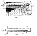
- Fig. 1 shows several radiation tubes (1, 2A, 2B) which have been mounted into a furnace, whereof a brick wall (3) is shown.
- the radiation tubes have a sheath which is a cylindrical tube (9) made from FeCrAl material.
- FeCrAl material means iron-chromium-aluminium-alloys as described above.
- a wall (not shown) from the same material.
- Into the wall (3) of the furnace is opened a hole which corresponds to the tube and wherein the end of the tube is supported.
- a corresponding support for example a shelf or an opening in the furnace wall.
- the distance between the walls of the furnace can be up to 2 meters and the radiation tube is hanging unsupported therein between.
- an electrical resistance element (4) which in the example shown is made from MoSi 2 of the kind which is marketed under the trademark KANTHAL SUPER.
- the element is resting on a ceramic support (5).
- the terminal parts (7) of the element pass through two plugs (6, 8), which separate the hot atmosphere of the radiation tube from the surroundings and support the terminal parts.
- the radiation tube shown in Fig. 2 is intended to be heated by an indicated gas burner (14).
- the combustion gases from the burner flow firstly through the insert (12), make a turn at the wall (10) and flow back along the radiation tube (9).
- the latter has a flange (11) for mounting to the furnace wall in a conventional way.
- Supports (13) are welded to the insert.
- the radiation tubes shown in figures 1 and 2 have dimensions chosen with respect to the furnace wherein they are to be used.
- the length of the tube may be 1800 mm, its external diameter 200 mm and wall thickness 8 mm.
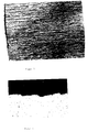
- Figures 3 and 4 show the appearance of a radiation tube according to the invention.
- Figure 3 is a photograph of the surface of the tube and figure 4 shows a cross section of the same surface of the tube at about 50 times magnification.
- the striped appearance of the surface is shown in the pictures. These crystal stripes are obtained by the use of a sufficient high shearing speed at the extrusion process and can be essential for the properties of the oxide layer.
Landscapes
- Engineering & Computer Science (AREA)
- Mechanical Engineering (AREA)
- General Engineering & Computer Science (AREA)
- Chemical & Material Sciences (AREA)
- Combustion & Propulsion (AREA)
- Resistance Heating (AREA)
- Combustion Of Fluid Fuel (AREA)
- Furnace Details (AREA)
- Gas Burners (AREA)
- Heat Treatment Of Articles (AREA)
- Extrusion Of Metal (AREA)
- Compositions Of Oxide Ceramics (AREA)
Description
- The present invention is for a heat radiation tube for furnaces and the like heating purposes. The source of heat can be electrical resistance elements or a burner using for example gas. Furnaces primarily means furnaces for heat treatment in industrial processes.
- Heat radiation tubes are mainly used in furnaces where the furnace atmosphere does not allow direct heat. This can be due to that the atmosphere is harmful to the elements which are being used for electrical heating or a wish to control the atmosphere in the furnace whereby combustion gases are not allowed therein. Other reasons for the use of radiation tubes instead of direct heating where such should be possible might be for example that one wants to repair or exchange the heat source while the furnace is being used. It will then be easier to do this in a separate space, e.g. inside the radiation tube, than in the furnace chamber itself.
- A heat radiation tube may comprise a cylindrical tube. A bottom is mounted in one end of the tube. In the other end of the tube there is as a rule a flange for mounting in the furnace wall. The tube can also have other arrangements, protrusions, etc. for mounting in the furnace as well as distance pieces and the like. Mainly when heating is obtained by combustion there may in the tube be inserts forming flow channels for the combustion gases. There are also U-shaped radiation tubes.
- Radiation tubes have hitherto mainly been used by furnace temperatures up to about 1100°C. The tubes are often made from an alloy mainly comprising nickel, chromium and iron. The alloy composition is for example 40-60 weight % nickel, 15-20 % chrom and 25-45 % iron. These radiation tubes, however, have certain drawbacks which are of great importance in most application. On the surfaces of the tubes the outside as well as the inside oxide layers are formed which are spalled off when they have reached a certain thickness, which varies due to conditions in each application. Hereby the oxide layers do not give protection against continuing attacks on the tubes. Downfalling oxide flakes may cause problems if they get into contact with the products which are present inside the furnaces. However, the greatest problems are caused by the oxide flakes inside the tubes. If these are holding electrical elements for the heating the flakes may cause short-circuiting between separate elements and between separate parts of one element which brings with it an immediate interruption of the function of the element or a considerably decreased life of the element. When an element is exchanged, which means that element and element support is pulled out from the radiation tube and after repair or exchange again is pushed into it,the supports may function as scrapes and bring about heaps of oxides in most cases in the far end of the tube which may cause difficulties by the repair work and function deficiencies.
- A radiation tube made of a FeCrNi alloy and comprising a heating element is disclosed in US-A-3,137,486. However, as explained above, the oxide layer is not stable at very high temperatures, which is a serious drawback. Furthermore, hitherto used radiation tubes do not have satisfactory mechanical properties by high temperatures of use. Due to their own weight and the internal load the tubes tend to sag. In order to compensate for this the tubes have to be turned 180° at regular intervals. This can in most cases be made in connection with normal maintenance or repair but it is still an important drawback and a factor which limits the possibilities of use.
- The object of the present invention is to avoid the above-mentioned drawbacks of hitherto known radiation tubes and to make possible a higher temperature of use than has hitherto been possible. This mainly refers to a higher constant temperature by continuous use. The invention also makes it possible to have longer intervals between stops for maintenance works. The much reduced or totally eliminated sagging of the tubes means much for reliable function of the radiation tubes as well as easier maintenance.
- Radiation tubes according to the invention are intended for use in furnaces and the like heating purposes and are characterized in
claim 1. A method of producing the tube is defined inclaim 3. Optional features of the invention are set out in the dependent claims. The cylindrical seamless sheath tube is made from an alloy of FeCrAl whereby a FeNiCr alloy is excluded . These radiation tubes have important advantages compared to conventional tubes made by casting or welding of plates from nickel chromium or iron-nickel-chromium-alloys. Radiation tubes according to the invention can be used at temperatures up to 1250-1300°C. - At high temperatures FeCrAl-alloys at oxidizing conditions form a stable and adhering layer of aluminium oxide on the surface of the material. This oxide is also more heat resistant and resistant against chemical attacks than the layers which are formed on nickel-chromium-alloys. This is particularly obvious in sulphur containing environments, where rapid and severe attacks are obtained on nickel-chromium materials. If the oxide layer is undamaged the FeCrAl-alloys are better also in carburizing atmosphere. In many applications forming the oxide layer by preoxidization according to the invention is therefore important also if the intended temperature of use is below 1100°C. Suitable pre-oxidation is for example heat treatment in air at 1100°C for at least 8 hours. The FeCrAl-alloy may also contain minor amounts of other alloying components such as yttrium, titanium and zirconium in amounts up to 0.2 weight % of each. These additives influence the oxide layers as well as the structure and properties of the material.
- The cylindrical tube which is a main part of the radiation tube is seam-less and preferably made by extrusion. The slab which is used for the extrusion is made in a well-known way be casting or by powder metallurgy. The shearing speed and other conditions by extrusion are choosen to give the tubes a striped surface which means that all of the outer surface of the tubes is rough with axially extending irregular grooves and ridges, the size of which is chosen to optimize the properties of the oxide layer, mainly its strength and elasticity, in order to avoid oxide spalling by high temperatures and changing temperature.
- Below the invention will be further described with reference to the accompanying figures.
- Fig. 1 shows electrically heated radiation tubes inside a furnace. One of the radiation tubes is shown with part of the tube cut away in order to show the element.
- Fig. 2 shows a cross section through a radiation tube which is heated by combustion of gas.
- Fig. 3 shows the surface of the cylindrical tube of a radiation tube.
- Fig. 4 shows a cross section of the cylindrical tube.
- Fig. 1 shows several radiation tubes (1, 2A, 2B) which have been mounted into a furnace, whereof a brick wall (3) is shown. The radiation tubes have a sheath which is a cylindrical tube (9) made from FeCrAl material. FeCrAl material means iron-chromium-aluminium-alloys as described above. At the outer end of the tube is a wall (not shown) from the same material. Into the wall (3) of the furnace is opened a hole which corresponds to the tube and wherein the end of the tube is supported. For the not shown end of the tube there is a corresponding support, for example a shelf or an opening in the furnace wall. The distance between the walls of the furnace can be up to 2 meters and the radiation tube is hanging unsupported therein between. Inside the tube there is an electrical resistance element (4) which in the example shown is made from MoSi2 of the kind which is marketed under the trademark KANTHAL SUPER. The element is resting on a ceramic support (5). The terminal parts (7) of the element pass through two plugs (6, 8), which separate the hot atmosphere of the radiation tube from the surroundings and support the terminal parts.
- The radiation tube shown in Fig. 2 is intended to be heated by an indicated gas burner (14). The combustion gases from the burner flow firstly through the insert (12), make a turn at the wall (10) and flow back along the radiation tube (9). The latter has a flange (11) for mounting to the furnace wall in a conventional way. Supports (13) are welded to the insert.
- The radiation tubes shown in figures 1 and 2 have dimensions chosen with respect to the furnace wherein they are to be used. For example, the length of the tube may be 1800 mm, its external diameter 200 mm and wall thickness 8 mm.
- Figures 3 and 4 show the appearance of a radiation tube according to the invention. Figure 3 is a photograph of the surface of the tube and figure 4 shows a cross section of the same surface of the tube at about 50 times magnification. The striped appearance of the surface is shown in the pictures. These crystal stripes are obtained by the use of a sufficient high shearing speed at the extrusion process and can be essential for the properties of the oxide layer.
Claims (4)
- Heat radiation tube for furnaces and the like, comprising a cylindrical tube made from an alloy with an outer oxide layer and having heating elements, characterized in that- the cylindrical tube is a seamless sheath tube (9) made from a FeCrAl alloy, wherein a tube made from a FeNiCr alloy is excluded; and- the oxide layer on the outer surface of the sheath tube (9) comprises mainly aluminium oxide and was made stable and adhering by preoxidation.
- Heat radiation tube according to claim 1,
characterized in that the outer surface of the sheath tube (9) is rough having irregular grooves and ridges extending along the tube. - Method of producing a heat radiation tube for furnaces or the like, comprising a cylindrical tube made from an alloy with an outer oxide layer and having a heating element, characterized in that- the heat radiation tube (1) is formed by disposing the heating element (4) inside a sheath tube (9);- the sheath tube (9) being made by extrusion of a FeCrAl alloy, wherein a tube made from a FeNiCr alloy is excluded; and- the outer oxide layer, on the outer surface of the sheath tube (9) comprising mainly aluminium oxide and being made stable and adhering by preoxidation.
- Method according to claim 3, characterized in that the extrusion is made at such a shearing speed that the outer surface of the sheath tube (9) is rough having irregular grooves and ridges extending along the tube.
Applications Claiming Priority (1)
| Application Number | Priority Date | Filing Date | Title |
|---|---|---|---|
| SE8704859A SE459524B (en) | 1987-12-04 | 1987-12-04 | VAERMESTRAALNINGSROER |
Publications (3)
| Publication Number | Publication Date |
|---|---|
| EP0321427A2 EP0321427A2 (en) | 1989-06-21 |
| EP0321427A3 EP0321427A3 (en) | 1989-07-05 |
| EP0321427B1 true EP0321427B1 (en) | 1996-08-28 |
Family
ID=20370503
Family Applications (1)
| Application Number | Title | Priority Date | Filing Date |
|---|---|---|---|
| EP88850409A Expired - Lifetime EP0321427B1 (en) | 1987-12-04 | 1988-12-05 | Heat radiation tube |
Country Status (5)
| Country | Link |
|---|---|
| EP (1) | EP0321427B1 (en) |
| KR (1) | KR0126475B1 (en) |
| DE (1) | DE3855704T2 (en) |
| ES (1) | ES2090017T3 (en) |
| SE (1) | SE459524B (en) |
Families Citing this family (4)
| Publication number | Priority date | Publication date | Assignee | Title |
|---|---|---|---|---|
| SE469754B (en) * | 1990-05-14 | 1993-09-06 | Kanthal Ab | OVEN BEFORE CRACKING THE PULP |
| KR930002869B1 (en) * | 1990-12-31 | 1993-04-12 | 포항종합제철 주식회사 | Heat dissipation tube for annealing furnace and manufacturing method |
| TW548334B (en) * | 1997-08-20 | 2003-08-21 | Jgc Corp | Heating furnace and method of manufacturing the same |
| FR2800450B1 (en) * | 1999-10-28 | 2002-01-04 | Stein Heurtey | DEVICE FOR INDIRECTLY HEATING FOSSIL FUEL OF RUNNING PRODUCTS, ESPECIALLY BANDS |
Family Cites Families (7)
| Publication number | Priority date | Publication date | Assignee | Title |
|---|---|---|---|---|
| US3137486A (en) * | 1962-11-28 | 1964-06-16 | Multifastener Company | Burner construction |
| US3735008A (en) * | 1970-03-20 | 1973-05-22 | Kokusai Electric Co Ltd | Electric furnace |
| US4011395A (en) * | 1975-09-15 | 1977-03-08 | Btu Engineering Company | Electric furnace heater |
| US3984616A (en) * | 1975-10-14 | 1976-10-05 | Btu Engineering Corporation | High temperature furnace heater |
| US4215233A (en) * | 1978-12-29 | 1980-07-29 | Alco Standard Corporation | Heating assembly with vibration dampening shipping supports for graphite heating elements |
| US4355973A (en) * | 1981-02-17 | 1982-10-26 | Caterpillar Tractor Co. | Radiant heating apparatus |
| US4589844A (en) * | 1984-07-25 | 1986-05-20 | Advanced Combustion Inc. | Heat exchange apparatus for industrial furnaces |
-
1987
- 1987-12-04 SE SE8704859A patent/SE459524B/en not_active IP Right Cessation
-
1988
- 1988-12-05 DE DE3855704T patent/DE3855704T2/en not_active Expired - Lifetime
- 1988-12-05 ES ES88850409T patent/ES2090017T3/en not_active Expired - Lifetime
- 1988-12-05 EP EP88850409A patent/EP0321427B1/en not_active Expired - Lifetime
- 1988-12-12 KR KR1019880016456A patent/KR0126475B1/en not_active Expired - Lifetime
Non-Patent Citations (1)
| Title |
|---|
| DIN 2462 * |
Also Published As
| Publication number | Publication date |
|---|---|
| KR0126475B1 (en) | 1997-12-26 |
| ES2090017T3 (en) | 1996-10-16 |
| SE8704859D0 (en) | 1987-12-04 |
| DE3855704T2 (en) | 1997-04-17 |
| DE3855704D1 (en) | 1997-01-23 |
| KR900010344A (en) | 1990-07-07 |
| EP0321427A2 (en) | 1989-06-21 |
| SE459524B (en) | 1989-07-10 |
| EP0321427A3 (en) | 1989-07-05 |
| SE8704859L (en) | 1989-06-05 |
Similar Documents
| Publication | Publication Date | Title |
|---|---|---|
| US5267609A (en) | Heat radiation tube | |
| US3975212A (en) | Thermocouple protective composite tube | |
| EP0321427A2 (en) | Heat radiation tube | |
| KR0173070B1 (en) | Thermocouple Protection Tube and Forming Method | |
| US6050723A (en) | High temperature thermocouple assembly for measuring molten metal temperatures | |
| US2336366A (en) | Furnace | |
| JPH0972789A (en) | Thermocouple temperature measuring device | |
| CA1142985A (en) | Melting and casting apparatus | |
| JP2941825B2 (en) | Radiator tube of iron-chromium-aluminum type alloy and method of manufacturing the same | |
| EP1344428B1 (en) | A resistor element for extreme temperatures | |
| JPH10237675A (en) | Firing furnace | |
| US3609199A (en) | Push-through furnace with graphite rod heating | |
| US3302352A (en) | Glass furnace bottom wall construction | |
| JPH03158696A (en) | Kiln | |
| JP3976460B2 (en) | Castable block glazing method | |
| JPH11166791A (en) | Sintering furnace | |
| CN215467863U (en) | Step furnace wall of natural gas forging continuous heating furnace | |
| CA1114873A (en) | Electrical insulation device | |
| RU2021571C1 (en) | Electric furnace dome section | |
| Lupi | Resistance Furnaces | |
| JP2002303416A (en) | Induction heating type continuous melting furnace | |
| JP2580216B2 (en) | Heater heater | |
| SU1028990A1 (en) | Rotating furnace | |
| EP0657086B1 (en) | Robust ceramic and metal-ceramic radiant heater designs for thin heating elements | |
| GB2189014A (en) | Segmented ceramic furnace baffle |
Legal Events
| Date | Code | Title | Description |
|---|---|---|---|
| PUAI | Public reference made under article 153(3) epc to a published international application that has entered the european phase |
Free format text: ORIGINAL CODE: 0009012 |
|
| PUAL | Search report despatched |
Free format text: ORIGINAL CODE: 0009013 |
|
| AK | Designated contracting states |
Kind code of ref document: A2 Designated state(s): DE ES FR GB IT SE |
|
| AK | Designated contracting states |
Kind code of ref document: A3 Designated state(s): DE ES FR GB IT SE |
|
| 18D | Application deemed to be withdrawn |
Effective date: 19900205 |
|
| 17P | Request for examination filed |
Effective date: 19921015 |
|
| D18D | Application deemed to be withdrawn (deleted) | ||
| 17Q | First examination report despatched |
Effective date: 19940919 |
|
| GRAH | Despatch of communication of intention to grant a patent |
Free format text: ORIGINAL CODE: EPIDOS IGRA |
|
| GRAH | Despatch of communication of intention to grant a patent |
Free format text: ORIGINAL CODE: EPIDOS IGRA |
|
| GRAA | (expected) grant |
Free format text: ORIGINAL CODE: 0009210 |
|
| AK | Designated contracting states |
Kind code of ref document: B1 Designated state(s): DE ES FR GB IT SE |
|
| ITF | It: translation for a ep patent filed | ||
| ET | Fr: translation filed | ||
| REG | Reference to a national code |
Ref country code: ES Ref legal event code: FG2A Ref document number: 2090017 Country of ref document: ES Kind code of ref document: T3 |
|
| REG | Reference to a national code |
Ref country code: ES Ref legal event code: FG2A Ref document number: 2090017 Country of ref document: ES Kind code of ref document: T3 |
|
| REF | Corresponds to: |
Ref document number: 3855704 Country of ref document: DE Date of ref document: 19970123 |
|
| PLBE | No opposition filed within time limit |
Free format text: ORIGINAL CODE: 0009261 |
|
| STAA | Information on the status of an ep patent application or granted ep patent |
Free format text: STATUS: NO OPPOSITION FILED WITHIN TIME LIMIT |
|
| 26N | No opposition filed | ||
| REG | Reference to a national code |
Ref country code: GB Ref legal event code: IF02 |
|
| REG | Reference to a national code |
Ref country code: GB Ref legal event code: 732E |
|
| REG | Reference to a national code |
Ref country code: FR Ref legal event code: TP |
|
| REG | Reference to a national code |
Ref country code: GB Ref legal event code: 732E |
|
| REG | Reference to a national code |
Ref country code: ES Ref legal event code: PC2A |
|
| REG | Reference to a national code |
Ref country code: GB Ref legal event code: 732E |
|
| REG | Reference to a national code |
Ref country code: FR Ref legal event code: TP |
|
| PGFP | Annual fee paid to national office [announced via postgrant information from national office to epo] |
Ref country code: SE Payment date: 20071205 Year of fee payment: 20 |
|
| PGFP | Annual fee paid to national office [announced via postgrant information from national office to epo] |
Ref country code: GB Payment date: 20071205 Year of fee payment: 20 Ref country code: FR Payment date: 20071210 Year of fee payment: 20 Ref country code: ES Payment date: 20080118 Year of fee payment: 20 |
|
| PGFP | Annual fee paid to national office [announced via postgrant information from national office to epo] |
Ref country code: IT Payment date: 20071228 Year of fee payment: 20 Ref country code: DE Payment date: 20071129 Year of fee payment: 20 |
|
| REG | Reference to a national code |
Ref country code: GB Ref legal event code: PE20 Expiry date: 20081204 |
|
| EUG | Se: european patent has lapsed | ||
| REG | Reference to a national code |
Ref country code: ES Ref legal event code: FD2A Effective date: 20081209 |
|
| PG25 | Lapsed in a contracting state [announced via postgrant information from national office to epo] |
Ref country code: ES Free format text: LAPSE BECAUSE OF EXPIRATION OF PROTECTION Effective date: 20081209 |
|
| PG25 | Lapsed in a contracting state [announced via postgrant information from national office to epo] |
Ref country code: GB Free format text: LAPSE BECAUSE OF EXPIRATION OF PROTECTION Effective date: 20081204 |