EP0321339A1 - Durchflussmengenregelungsvorrichtung für eine abwechselnde Dosierpumpe - Google Patents
Durchflussmengenregelungsvorrichtung für eine abwechselnde Dosierpumpe Download PDFInfo
- Publication number
- EP0321339A1 EP0321339A1 EP88403176A EP88403176A EP0321339A1 EP 0321339 A1 EP0321339 A1 EP 0321339A1 EP 88403176 A EP88403176 A EP 88403176A EP 88403176 A EP88403176 A EP 88403176A EP 0321339 A1 EP0321339 A1 EP 0321339A1
- Authority
- EP
- European Patent Office
- Prior art keywords
- motor
- adjusting
- movement
- electronic circuit
- supply
- Prior art date
- Legal status (The legal status is an assumption and is not a legal conclusion. Google has not performed a legal analysis and makes no representation as to the accuracy of the status listed.)
- Granted
Links
Images

Classifications
-
- G—PHYSICS
- G01—MEASURING; TESTING
- G01F—MEASURING VOLUME, VOLUME FLOW, MASS FLOW OR LIQUID LEVEL; METERING BY VOLUME
- G01F11/00—Apparatus requiring external operation adapted at each repeated and identical operation to measure and separate a predetermined volume of fluid or fluent solid material from a supply or container, without regard to weight, and to deliver it
- G01F11/02—Apparatus requiring external operation adapted at each repeated and identical operation to measure and separate a predetermined volume of fluid or fluent solid material from a supply or container, without regard to weight, and to deliver it with measuring chambers which expand or contract during measurement
- G01F11/021—Apparatus requiring external operation adapted at each repeated and identical operation to measure and separate a predetermined volume of fluid or fluent solid material from a supply or container, without regard to weight, and to deliver it with measuring chambers which expand or contract during measurement of the piston type
- G01F11/023—Apparatus requiring external operation adapted at each repeated and identical operation to measure and separate a predetermined volume of fluid or fluent solid material from a supply or container, without regard to weight, and to deliver it with measuring chambers which expand or contract during measurement of the piston type with provision for varying the stroke of the piston
-
- F—MECHANICAL ENGINEERING; LIGHTING; HEATING; WEAPONS; BLASTING
- F04—POSITIVE - DISPLACEMENT MACHINES FOR LIQUIDS; PUMPS FOR LIQUIDS OR ELASTIC FLUIDS
- F04B—POSITIVE-DISPLACEMENT MACHINES FOR LIQUIDS; PUMPS
- F04B13/00—Pumps specially modified to deliver fixed or variable measured quantities
-
- F—MECHANICAL ENGINEERING; LIGHTING; HEATING; WEAPONS; BLASTING
- F04—POSITIVE - DISPLACEMENT MACHINES FOR LIQUIDS; PUMPS FOR LIQUIDS OR ELASTIC FLUIDS
- F04B—POSITIVE-DISPLACEMENT MACHINES FOR LIQUIDS; PUMPS
- F04B49/00—Control, e.g. of pump delivery, or pump pressure of, or safety measures for, machines, pumps, or pumping installations, not otherwise provided for, or of interest apart from, groups F04B1/00 - F04B47/00
- F04B49/06—Control using electricity
Definitions
- a microprocessor which, from an input data corresponding to the desired flow expressed as a fraction of the maximum flow of the pump, or from two input data corresponding to the stroke and the desired cadence, proceeds to the selection of parameters useful for controlling the motor from among the values it contains in memory and manages the control of this motor as a function of the parameters selected.
- the present invention intends to extend the advantages of a flow control which does not intervene on the mechanical elements by means of stroke limiting members. the adjustment of which is always delicate and subject to adjustment, or by the use of servomotors, by implementing means which are simplified compared to the means described in the French patent mentioned above.
- the invention therefore relates to a device for adjusting the flow rate of a metering pump comprising a pumping member coupled to a transmission member converting the rotary movement of a reversible drive motor into an alternating movement of the pumping member, comprising means for adjusting the amplitude of the reciprocating movement and means for adjusting the period of this movement.
- the means for adjusting the amplitude of the reciprocating movement comprise: a sensor for the displacement of the transmission member, emitting a plurality of pulses, the number of which is converted into an analog value as a function of the value of the amplitude of the displacement, - a comparator of said analog value to an adjustable setpoint outputting a signal when the compared values are equal, - an electronic control circuit receiving as input the signal emitted by the comparator, which in response to this signal on the one hand switches the power supply to the motor to reverse its direction of rotation and, on the other hand, activates detection means the return of the transmission member to an original position, these detection means emitting towards the electronic circuit a signal when the original position is reached, in response to which the logic circuit controls the interruption of the power supply to the motor, while the means for adjusting the period of movement are constituted by a pulse transmitter in the direction of the electronic circuit, in response to which the latter establishes the supply of the engine to move the transmission member away from said original position.
- the senor for the displacement of the transmission member is constituted by an optical encoder locked in rotation on a rotary element of the transmission member driven by the motor.
- the means for detecting the original position are constituted by a counter for the pulses of the alternating current supplying the motor, reset to zero at each pulse emitted by the optical encoder, the latter having an inactive range in the vicinity of the origin position in which no pulse is emitted, the counter emitting a signal towards the electronic circuit when the pulses counted are equal to a set value.
- the logic circuit can be connected to an internal pulse transmitter, which makes it possible to regulate the pump flow in an absolute manner, or can be connected to an external pulse transmitter, which allows to control the flow of the pump to another quantity, for example the flow rate of the fluid in the main pipe into which the doses are injected, the external pulse emitter then being a flow meter.
- a socket is used to select one or other of the transmitters, the external transmitter being connectable to the device by a plug-in connector.
- a reversible and synchronous motor 1 driving by means of a reduction gear 2.3 of a crankshaft 4 kept rotating in bearings 5 and 6 of a frame 7.
- the crankshaft sleeve carries the foot 8 of an actuating rod of a pumping member not shown, which can be a piston or a membrane.
- the motor 1 is a reversible synchronous motor having two windings 9 a and 9 b
- a device for controlling the supply of these windings is provided in the following manner.
- windings The common point of these windings is connected to an AC supply terminal 10 of known frequency (for example 50 Hz).
- Each of the windings is also connected to the other terminal 11 of this source by means of a optocoupled triac 12,13 with a light-emitting diode 14,15 which constitutes the control member.
- a capacitor 16 is arranged in a known manner between the two windings 9 a and 9 b .
- the triac 12 When the triac 12 is made conductive, the windings are supplied one 9 a by the mains voltage and the other 9 b by a phase-shifted voltage due to the capacitor, causing the crankshaft to rotate in a first direction of rotation.
- the reversal of direction of rotation is obtained by switching the power supply, the triac 12 no longer passing while the triac 13 is made conductive.
- the excitation of the diodes 14 and 15 is carried out by a control unit 17 in operation of the different supply phases of the motor 1 which it is desired to achieve in order to obtain the desired flow rate of the pump.
- This control unit 17 firstly comprises means for adjusting the travel of the moving assembly. These means comprise a member 20 for selecting a set value corresponding to the desired stroke of the connecting rod. This stroke can be expressed as a fraction (%) of the total stroke by means of a manually controlled potentiometer delivering an analog value (voltage) proportional to the desired fraction.
- This set value is introduced into a comparator 21 which also receives a variable voltage generated by a converter 22.
- the latter receives as input the pulses delivered by an optical encoder 23.
- the number of these pulses is related to the angular travel of a disc 23 a belonging to the encoder and a more precise description of which will be given with reference to FIG. 2.
- This disc 23 a is integral with the wheel 3 of the reduction gear 2,3 itself locked in rotation on the crankshaft 4.
- An optical encoder of another type could be used in this device. It could in particular be a displacement sensor of the connecting rod or of the pumping member, emitting an analog or digital value converted to be compared with the set value.
- the electronic circuit 24 by means of a control logic which it possesses, activates a counter 22 a belonging to the converter 22.
- the control logic then receives as input 25 pulses corresponding to the frequency of the mains supply alternating current (in fact, at the frequency of 100 Hz counts given by the diode bridge 26 and the diode 26 a ) and directs these pulses from the sector to the counter 22 a of the converter 22.
- This counter is reset to zero by each of the pulses emitted by the optical encoder 23 rotating in opposite directions.
- the optical encoder has an angular range defined with respect to a position of the crankshaft (for example in the vicinity of its position corresponding to the dead center before the pumping member), during which it no longer emits a pulse.
- the counter 22 a is then no longer reset to zero count the pulses it receives as an input until it has reached a number corresponding to a determined set value.
- the converter 22 delivers a signal in the direction of the electronic circuit 24 which, in response, controls the extinction of the diode 15.
- the engine stops and the moving element is in a position called the home position (by example the neutral position before).
- the start of a new pumping cycle is controlled by the circuit 24 which excites the diode 14 in response to a signal which it receives on one of the two inputs 27 a and 27 b .
- the input 27 a is connected to the output of a pulse generator 28 whose frequency can be manually adjusted by means, for example of a potentiometer 29, integrated in an RC type circuit.
- This generator can be of any known type and, if it is digital, include independent clock means. By adjusting the frequency of these pulses the cycle time is adjusted.
- the circuit 24 can receive on its input 27 b pulses emitted by an external generator (for example a flow meter). Under these conditions, the rate of the pump and, for a given stroke, its flow, can be controlled by an external parameter of the flow type of circulation of the fluid in which the doses are introduced.
- This external generator can be connected to the device by a plug-in cord at 30, and this connection has the effect of controlling a switch 31 which isolates the circuit 24 from the internal timer 28.
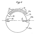
- FIG. 2 there is shown the disc 23 a which is part of the optical encoder 23 and which cooperates with a sensor 23 b , known in itself.
- This disc has a plurality of slots 32,33,34 and a notch 35.
- the sensor 23 b emits a pulse on the passage of each slot. This pulse increments the counter 22 a of the converter 22 during the suction stroke of the pump and resets this counter to zero during the reverse stroke, as explained above.
- the rotation of the disc 23 a during the suction stroke is indicated by the arrow A in FIG. 2.
- the spacing of the slots defined by the angle at the center between two successive slots will depend on the sensitivity of the adjustment that we want to give to the pump, and will have to satisfy the sinusoidal function which governs the stroke of the connecting rod head. depending on the angle of rotation of the crankshaft sleeve.
- the eccentricity of the sleeve is at least ten times less than the length of the connecting rod, the angular spacing of the slots on the disc responds to a function of the arc-sine type of each fraction of the desired stroke.
- the sensitivity of the adjustment finds a limit due to the operation of the triacs. Indeed, it is known that these become blocking in the absence of excitation of the light-emitting diode and at the passage of the supply current to zero. Thus a triac does not cut the power supply which it controls at the latest 10 milliseconds after the extinction of the diode, for a current of frequency 50 Hz.
- the slot 33 is in turn distant from the adjacent slot 32 by twice the aforementioned angle (20 milliseconds) and the slot 34 is located relative to the slot 33 at three times this angle. Given their situation with respect to rear dead center (P MAR), the error made with respect to the theoretical race is extremely small. It will be noted that the slot 34 which corresponds to 100% of the travel, is distant from the rear dead center by 10 milliseconds (in time) which correspond to a rest time required when switching the triacs.
- the notch 35 of the disc 23 a is such that when it moves opposite the sensor 23 b , no pulse is transmitted to the counter 22 a .
- the latter can therefore count the pulses corresponding to the frequency of the network during the return stroke of the moving assembly.
- the operation of the device according to the invention operates as follows. It will first be assumed that the pump operates independently as a function of the set values displayed by means of the members 20 and 29.
- the first pulse emitted by the timer 28 reaches the logic circuit 24 which excites the diode 14.
- the motor is powered to turn in one direction. It quickly hooks up its synchronism speed (generally within the first half-period of the supply current).
- the disc 23 a rotates in the direction A and the encoder 23 emits pulses in the direction of the counter 22 a and converter 22, until obtaining an equality noted by the comparator 21 which by its output signal imposes on the circuit 24, of a on the one hand, to interrupt the excitation of the diode 14, and on the other hand after a time delay of the order of 10 milliseconds to excite the diode 15.
- the triac 13 having turned on, the motor turns in the opposite direction .
- the circuit 24 by an incorporated control logic places the counter-converter unit 22, 22 a in a state in which the counter can count the pulses received at input 25 and corresponding to the frequency of the rectified sector, while that it is, on each pulse, emitted by the encoder 23, reset to zero.
- the disc 23 a rotates in the opposite direction to the direction A.
- the edge 35 a of the notch 35 is read as a slot and places the counter 22 a at zero.
- the latter then counts the half-periods of the network current until obtaining a number equal to that determined which it has on deposit at the time of construction (for example 6).
- the converter at this time emits a signal for the circuit 24 which interrupts the excitation of the diode 15.
- the motor will stop at the end of the next half-period and the disc will be in the position of FIG. 2 which corresponds, if so chosen in neutral before the moving part. It is understood that this position is repeatedly reached at the end of each return stroke of the moving assembly. It is an extremely reliable home position.
- FIG. 1 shows by reference 18 the supply to the comparator 21 of a setpoint signal (current or voltage) which, as an alternative to that set by the potentiometer 20, makes it possible to control the length of the stroke at this value variable set point.
- the electronic member 18 is used to filter, shape and on a scale compatible with the comparator 21, in particular by adjusting the zero and the gain of this member, a current or a voltage coming from a sensor (pH, flow rate, viscosity ...) or a regulator depending on whether you want to achieve an open loop or closed loop control. Putting this servo-control into service by switching off the potentiometer 20 by opening a switch 19 which can be carried out mechanically when a plug-in connector is put in place.
- control unit 17 and the opto-coupled triacs for controlling the supply of the motor can be grouped together in the same housing.
- the pump may then have only plug-in connection sockets at the level of the motor windings and at the level of the encoder 23.
- Two connection cables may suffice, on the one hand, to connect the encoder to the housing and, on the other hand, to supply the engine from the control box via the triacs.
- the pump is then simply supplied by the mains current supplied to the terminals of the motor windings, and operates like an ordinary pump at a fixed flow rate (its maximum flow rate), the crankshaft rotating in a continuous movement.
- the pump provided with the optical encoder can be connected to a programmable controller or a computer or a microprocessor with interface electronics comprising the opto-coupled triacs or static relays, in which the electronic circuit 24 and the control logic would be replaced by a program comprising control instructions as a function of the signals received and the set values.
- the invention finds an interesting application in the field of metering pumps.
Priority Applications (1)
| Application Number | Priority Date | Filing Date | Title |
|---|---|---|---|
| AT88403176T ATE66725T1 (de) | 1987-12-17 | 1988-12-14 | Durchflussmengenregelungsvorrichtung fuer eine abwechselnde dosierpumpe. |
Applications Claiming Priority (2)
| Application Number | Priority Date | Filing Date | Title |
|---|---|---|---|
| FR8717635A FR2624919B1 (fr) | 1987-12-17 | 1987-12-17 | Dispositif de reglage du debit d'une pompe doseuse alternative |
| FR8717635 | 1987-12-17 |
Publications (2)
| Publication Number | Publication Date |
|---|---|
| EP0321339A1 true EP0321339A1 (de) | 1989-06-21 |
| EP0321339B1 EP0321339B1 (de) | 1991-08-28 |
Family
ID=9357980
Family Applications (1)
| Application Number | Title | Priority Date | Filing Date |
|---|---|---|---|
| EP88403176A Expired - Lifetime EP0321339B1 (de) | 1987-12-17 | 1988-12-14 | Durchflussmengenregelungsvorrichtung für eine abwechselnde Dosierpumpe |
Country Status (9)
| Country | Link |
|---|---|
| US (1) | US4925371A (de) |
| EP (1) | EP0321339B1 (de) |
| JP (1) | JPH01280695A (de) |
| AT (1) | ATE66725T1 (de) |
| CA (1) | CA1303703C (de) |
| DE (2) | DE3864503D1 (de) |
| ES (1) | ES2009735B3 (de) |
| FR (1) | FR2624919B1 (de) |
| GR (2) | GR890300134T1 (de) |
Cited By (1)
| Publication number | Priority date | Publication date | Assignee | Title |
|---|---|---|---|---|
| WO1997003290A1 (de) * | 1995-07-13 | 1997-01-30 | Knf Flodos Ag | Dosierpumpe |
Families Citing this family (15)
| Publication number | Priority date | Publication date | Assignee | Title |
|---|---|---|---|---|
| US5131816A (en) * | 1988-07-08 | 1992-07-21 | I-Flow Corporation | Cartridge fed programmable ambulatory infusion pumps powered by DC electric motors |
| US5182826A (en) * | 1989-03-09 | 1993-02-02 | Ssi Medical Services, Inc. | Method of blower control |
| US5195873A (en) * | 1992-03-13 | 1993-03-23 | C.A.P., Inc. | Chemical transfer system |
| US5676525A (en) * | 1993-02-19 | 1997-10-14 | Neovation Ag | Vacuum limiting medical pump |
| DE10162773A1 (de) * | 2001-12-20 | 2003-07-10 | Knf Flodos Ag Sursee | Dosierpumpe |
| AU2003284657A1 (en) * | 2002-11-28 | 2004-06-18 | Tacmina Corporation | Metered quantity transfer device |
| EP1602826B1 (de) * | 2004-06-04 | 2007-06-27 | Société Industrielle de Sonceboz S.A. | Pumpenantrieb |
| US7275474B2 (en) * | 2005-05-31 | 2007-10-02 | Parker-Hannifincorporation | Optical position sensing and method |
| DE102009020412A1 (de) * | 2009-05-08 | 2010-11-18 | Lewa Gmbh | Verfahren und Vorrichtung zum Mischen von Fluiden |
| US8535026B2 (en) * | 2010-06-30 | 2013-09-17 | Schlumberger Technology Corporation | Mechanical system for movement along a housing axis |
| WO2013013725A1 (en) * | 2011-07-28 | 2013-01-31 | Ecolab Inc. | A diaphragm pump for dosing a fluid and an according method |
| DE102012214385A1 (de) * | 2012-08-13 | 2014-02-13 | Zf Friedrichshafen Ag | Vorrichtung zum Bewegen wenigstens eines Bauteiles |
| CN107387380A (zh) * | 2016-05-14 | 2017-11-24 | 勇猛机械股份有限公司 | 一种收获机中电子泵的控制装置 |
| US10458402B2 (en) * | 2016-07-25 | 2019-10-29 | Xiamen Conjoin Electronics Technology Co., Ltd. | Micro water pump capable of controlling flow precisely |
| US10856668B2 (en) * | 2017-04-10 | 2020-12-08 | Hill-Rom Services, Inc. | Mattress overlay control system with rotary valves and graphical user interface for percussion and vibration, turn assist and microclimate management |
Citations (6)
| Publication number | Priority date | Publication date | Assignee | Title |
|---|---|---|---|---|
| GB1176870A (en) * | 1967-11-07 | 1970-01-07 | English Electric Co Ltd | Motor Control System. |
| FR2331021A1 (fr) * | 1975-11-10 | 1977-06-03 | Varian Associates | Systeme de chromatographie en phase liquide ou la soupape d'entree de la pompe est positivement entrainee |
| EP0025575A1 (de) * | 1979-09-13 | 1981-03-25 | Roche Diagnostics GmbH | Dosiervorrichtung |
| FR2500081A1 (fr) * | 1981-02-17 | 1982-08-20 | Hartmann & Laemmle | Pompe doseuse |
| DE3301741A1 (de) * | 1983-01-20 | 1984-07-26 | Bosch Gmbh Robert | Kraftstoffpumpe mit permanentmagnetischer vorerregung und geregeltem kolbenhub |
| FR2588319A1 (fr) * | 1985-10-04 | 1987-04-10 | Milton Roy Dosapro | Procede pour etablir de maniere precise le debit d'une pompe doseuse et pompe doseuse faisant application |
Family Cites Families (3)
| Publication number | Priority date | Publication date | Assignee | Title |
|---|---|---|---|---|
| US3985019A (en) * | 1975-11-10 | 1976-10-12 | Boehme Detlef R | Liquid chromatography system with solvent proportioning |
| FR2461126A1 (fr) * | 1978-12-15 | 1981-01-30 | Gilson Medical Electronic Fran | Pompe a piston a debit reglable precisement |
| US4681513A (en) * | 1985-02-01 | 1987-07-21 | Jeol Ltd. | Two-stage pump assembly |
-
1987
- 1987-12-17 FR FR8717635A patent/FR2624919B1/fr not_active Expired - Lifetime
-
1988
- 1988-12-14 EP EP88403176A patent/EP0321339B1/de not_active Expired - Lifetime
- 1988-12-14 DE DE8888403176T patent/DE3864503D1/de not_active Expired - Lifetime
- 1988-12-14 DE DE198888403176T patent/DE321339T1/de active Pending
- 1988-12-14 ES ES88403176T patent/ES2009735B3/es not_active Expired - Lifetime
- 1988-12-14 US US07/284,630 patent/US4925371A/en not_active Expired - Fee Related
- 1988-12-14 AT AT88403176T patent/ATE66725T1/de not_active IP Right Cessation
- 1988-12-16 JP JP63316543A patent/JPH01280695A/ja active Pending
- 1988-12-16 CA CA000586116A patent/CA1303703C/fr not_active Expired - Lifetime
-
1990
- 1990-01-19 GR GR89300134T patent/GR890300134T1/el unknown
-
1991
- 1991-11-07 GR GR91401684T patent/GR3003075T3/el unknown
Patent Citations (6)
| Publication number | Priority date | Publication date | Assignee | Title |
|---|---|---|---|---|
| GB1176870A (en) * | 1967-11-07 | 1970-01-07 | English Electric Co Ltd | Motor Control System. |
| FR2331021A1 (fr) * | 1975-11-10 | 1977-06-03 | Varian Associates | Systeme de chromatographie en phase liquide ou la soupape d'entree de la pompe est positivement entrainee |
| EP0025575A1 (de) * | 1979-09-13 | 1981-03-25 | Roche Diagnostics GmbH | Dosiervorrichtung |
| FR2500081A1 (fr) * | 1981-02-17 | 1982-08-20 | Hartmann & Laemmle | Pompe doseuse |
| DE3301741A1 (de) * | 1983-01-20 | 1984-07-26 | Bosch Gmbh Robert | Kraftstoffpumpe mit permanentmagnetischer vorerregung und geregeltem kolbenhub |
| FR2588319A1 (fr) * | 1985-10-04 | 1987-04-10 | Milton Roy Dosapro | Procede pour etablir de maniere precise le debit d'une pompe doseuse et pompe doseuse faisant application |
Cited By (2)
| Publication number | Priority date | Publication date | Assignee | Title |
|---|---|---|---|---|
| WO1997003290A1 (de) * | 1995-07-13 | 1997-01-30 | Knf Flodos Ag | Dosierpumpe |
| US5971723A (en) * | 1995-07-13 | 1999-10-26 | Knf Flodos Ag | Dosing pump |
Also Published As
| Publication number | Publication date |
|---|---|
| EP0321339B1 (de) | 1991-08-28 |
| DE3864503D1 (de) | 1991-10-02 |
| ATE66725T1 (de) | 1991-09-15 |
| JPH01280695A (ja) | 1989-11-10 |
| GR3003075T3 (en) | 1993-02-17 |
| DE321339T1 (de) | 1989-11-16 |
| ES2009735B3 (es) | 1992-03-16 |
| US4925371A (en) | 1990-05-15 |
| FR2624919A1 (fr) | 1989-06-23 |
| GR890300134T1 (en) | 1990-01-19 |
| ES2009735A4 (es) | 1989-10-16 |
| CA1303703C (fr) | 1992-06-16 |
| FR2624919B1 (fr) | 1990-04-27 |
Similar Documents
| Publication | Publication Date | Title |
|---|---|---|
| EP0321339B1 (de) | Durchflussmengenregelungsvorrichtung für eine abwechselnde Dosierpumpe | |
| EP0223643B1 (de) | Prozess um genau den Förderstrom einer Dosierpumpe zu bestimmen und solche Pumpe | |
| EP0363264B1 (de) | Synchronmotor, dessen Drehrichtung gewählt werden kann | |
| FR2575514A1 (fr) | Systeme de commande pour une porte automatique | |
| FR2461126A1 (fr) | Pompe a piston a debit reglable precisement | |
| FR2540308A1 (fr) | Procede et systeme de commande d'un moteur a commutateur electronique | |
| EP1376056A1 (de) | Modulares System zur Erzeugung einer Referenzebene mittels Laser | |
| FR2478021A1 (fr) | Dispositif de commande pour avion permettant le passage automatique/manuel de facon instantanee | |
| FR2920287A1 (fr) | Procede pour mesurer la quantite de cafe distribuee par un moulin a cafe et appareil comprenant un tel moulin | |
| EP1675253B1 (de) | Verfahren zum Betrieb eines Heimnetzwerkes mit einer Betätigungseinrichtung und einer Steuereinheit | |
| FR2485292A1 (fr) | Ensemble de conversion electromecanique d'energie a machine sans balai et son procede de commande | |
| FR2788175A1 (fr) | Commande de moteurs pas-a-pas | |
| EP0054446B1 (de) | Elektrischer Asynchronmotor, Einrichtung zum Regeln der Speisung eines solchen Motors und Umwälzantrieb mit einem solchen Motor | |
| FR2628286A1 (fr) | Compteur de recolte pour moissonneuse-batteuse | |
| EP2172143B1 (de) | Steuerverfahren zum Bewegen eines Elementes eines Elektrohaushaltgeräts, insbesondere einer Bedienblende eines Backofens | |
| EP0732438A1 (de) | Vorrichtung eingebaut in einem elektrischen Motor für eine Waschmaschine, eine Geschirrspülmaschine oder dergleichen | |
| FR2864723A1 (fr) | Dispositif de commande pour un generateur electrique de vehicule a moteur | |
| FR2638861A1 (fr) | Programmateur, notamment pour appareil electromenager | |
| FR2972409A1 (fr) | Procede et dispositif de controle d'un moteur electrique d'essuie-glace | |
| FR3079177A1 (fr) | Dispositif de correction d’eclairage a moteur electrique a courant continu pour vehicule automobile. | |
| BE1011536A3 (fr) | Procede de controle pour prehenseur. | |
| EP0401449A1 (de) | Abgabe- und Dosiervorrichtung für Wasch- oder Reinigungsanlagen | |
| FR2606229A1 (fr) | Systeme de commande d'un moteur asynchrone monophase destine a l'entrainement d'un objet tel qu'un store du type a lames orientables | |
| FR3081517A1 (fr) | Dispositif generateur d'electricite | |
| FR3110305A1 (fr) | Dispositif de freinage d’outil en rotation dans un appareil de préparation culinaire |
Legal Events
| Date | Code | Title | Description |
|---|---|---|---|
| PUAI | Public reference made under article 153(3) epc to a published international application that has entered the european phase |
Free format text: ORIGINAL CODE: 0009012 |
|
| 17P | Request for examination filed |
Effective date: 19881215 |
|
| AK | Designated contracting states |
Kind code of ref document: A1 Designated state(s): AT BE CH DE ES GB GR IT LI LU NL SE |
|
| ITCL | It: translation for ep claims filed |
Representative=s name: INGG. GUZZI RAVIZZA |
|
| GBC | Gb: translation of claims filed (gb section 78(7)/1977) | ||
| TCAT | At: translation of patent claims filed | ||
| TCNL | Nl: translation of patent claims filed | ||
| DET | De: translation of patent claims | ||
| 17Q | First examination report despatched |
Effective date: 19900724 |
|
| GRAA | (expected) grant |
Free format text: ORIGINAL CODE: 0009210 |
|
| AK | Designated contracting states |
Kind code of ref document: B1 Designated state(s): AT BE CH DE ES GB GR IT LI LU NL SE |
|
| REF | Corresponds to: |
Ref document number: 66725 Country of ref document: AT Date of ref document: 19910915 Kind code of ref document: T |
|
| REF | Corresponds to: |
Ref document number: 3864503 Country of ref document: DE Date of ref document: 19911002 |
|
| ITF | It: translation for a ep patent filed |
Owner name: GUZZI E RAVIZZA S.R.L. |
|
| GBT | Gb: translation of ep patent filed (gb section 77(6)(a)/1977) | ||
| PGFP | Annual fee paid to national office [announced via postgrant information from national office to epo] |
Ref country code: LU Payment date: 19911204 Year of fee payment: 4 |
|
| PGFP | Annual fee paid to national office [announced via postgrant information from national office to epo] |
Ref country code: CH Payment date: 19911206 Year of fee payment: 4 |
|
| PGFP | Annual fee paid to national office [announced via postgrant information from national office to epo] |
Ref country code: SE Payment date: 19911216 Year of fee payment: 4 |
|
| PGFP | Annual fee paid to national office [announced via postgrant information from national office to epo] |
Ref country code: AT Payment date: 19911227 Year of fee payment: 4 |
|
| PGFP | Annual fee paid to national office [announced via postgrant information from national office to epo] |
Ref country code: GR Payment date: 19911230 Year of fee payment: 4 |
|
| PGFP | Annual fee paid to national office [announced via postgrant information from national office to epo] |
Ref country code: NL Payment date: 19911231 Year of fee payment: 4 |
|
| PGFP | Annual fee paid to national office [announced via postgrant information from national office to epo] |
Ref country code: BE Payment date: 19920102 Year of fee payment: 4 |
|
| REG | Reference to a national code |
Ref country code: ES Ref legal event code: FG2A Ref document number: 2009735 Country of ref document: ES Kind code of ref document: B3 |
|
| EPTA | Lu: last paid annual fee | ||
| PLBE | No opposition filed within time limit |
Free format text: ORIGINAL CODE: 0009261 |
|
| STAA | Information on the status of an ep patent application or granted ep patent |
Free format text: STATUS: NO OPPOSITION FILED WITHIN TIME LIMIT |
|
| 26N | No opposition filed | ||
| REG | Reference to a national code |
Ref country code: GR Ref legal event code: FG4A Free format text: 3003075 |
|
| PG25 | Lapsed in a contracting state [announced via postgrant information from national office to epo] |
Ref country code: LU Free format text: LAPSE BECAUSE OF NON-PAYMENT OF DUE FEES Effective date: 19921214 Ref country code: AT Effective date: 19921214 |
|
| PG25 | Lapsed in a contracting state [announced via postgrant information from national office to epo] |
Ref country code: SE Effective date: 19921215 |
|
| PG25 | Lapsed in a contracting state [announced via postgrant information from national office to epo] |
Ref country code: LI Effective date: 19921231 Ref country code: CH Effective date: 19921231 Ref country code: BE Effective date: 19921231 |
|
| BERE | Be: lapsed |
Owner name: DOSAPRO MILTON ROY Effective date: 19921231 |
|
| PG25 | Lapsed in a contracting state [announced via postgrant information from national office to epo] |
Ref country code: GR Free format text: THE PATENT HAS BEEN ANNULLED BY A DECISION OF A NATIONAL AUTHORITY Effective date: 19930630 |
|
| PG25 | Lapsed in a contracting state [announced via postgrant information from national office to epo] |
Ref country code: NL Effective date: 19930701 |
|
| NLV4 | Nl: lapsed or anulled due to non-payment of the annual fee | ||
| REG | Reference to a national code |
Ref country code: CH Ref legal event code: PL |
|
| PGFP | Annual fee paid to national office [announced via postgrant information from national office to epo] |
Ref country code: GB Payment date: 19931129 Year of fee payment: 6 |
|
| PGFP | Annual fee paid to national office [announced via postgrant information from national office to epo] |
Ref country code: ES Payment date: 19931210 Year of fee payment: 6 |
|
| PGFP | Annual fee paid to national office [announced via postgrant information from national office to epo] |
Ref country code: DE Payment date: 19940128 Year of fee payment: 6 |
|
| PG25 | Lapsed in a contracting state [announced via postgrant information from national office to epo] |
Ref country code: GB Effective date: 19941214 |
|
| REG | Reference to a national code |
Ref country code: GR Ref legal event code: MM2A Free format text: 3003075 |
|
| EUG | Se: european patent has lapsed |
Ref document number: 88403176.6 Effective date: 19930709 |
|
| GBPC | Gb: european patent ceased through non-payment of renewal fee |
Effective date: 19941214 |
|
| PG25 | Lapsed in a contracting state [announced via postgrant information from national office to epo] |
Ref country code: DE Effective date: 19950901 |
|
| PG25 | Lapsed in a contracting state [announced via postgrant information from national office to epo] |
Ref country code: ES Free format text: LAPSE BECAUSE OF NON-PAYMENT OF DUE FEES Effective date: 19951215 |
|
| REG | Reference to a national code |
Ref country code: ES Ref legal event code: FD2A Effective date: 19960113 |
|
| PG25 | Lapsed in a contracting state [announced via postgrant information from national office to epo] |
Ref country code: IT Free format text: LAPSE BECAUSE OF NON-PAYMENT OF DUE FEES;WARNING: LAPSES OF ITALIAN PATENTS WITH EFFECTIVE DATE BEFORE 2007 MAY HAVE OCCURRED AT ANY TIME BEFORE 2007. THE CORRECT EFFECTIVE DATE MAY BE DIFFERENT FROM THE ONE RECORDED. Effective date: 20051214 |