EP0321339A1 - Flow rate regulating system for an alternating dosing pump - Google Patents
Flow rate regulating system for an alternating dosing pump Download PDFInfo
- Publication number
- EP0321339A1 EP0321339A1 EP88403176A EP88403176A EP0321339A1 EP 0321339 A1 EP0321339 A1 EP 0321339A1 EP 88403176 A EP88403176 A EP 88403176A EP 88403176 A EP88403176 A EP 88403176A EP 0321339 A1 EP0321339 A1 EP 0321339A1
- Authority
- EP
- European Patent Office
- Prior art keywords
- motor
- adjusting
- movement
- electronic circuit
- supply
- Prior art date
- Legal status (The legal status is an assumption and is not a legal conclusion. Google has not performed a legal analysis and makes no representation as to the accuracy of the status listed.)
- Granted
Links
Images

Classifications
-
- G—PHYSICS
- G01—MEASURING; TESTING
- G01F—MEASURING VOLUME, VOLUME FLOW, MASS FLOW OR LIQUID LEVEL; METERING BY VOLUME
- G01F11/00—Apparatus requiring external operation adapted at each repeated and identical operation to measure and separate a predetermined volume of fluid or fluent solid material from a supply or container, without regard to weight, and to deliver it
- G01F11/02—Apparatus requiring external operation adapted at each repeated and identical operation to measure and separate a predetermined volume of fluid or fluent solid material from a supply or container, without regard to weight, and to deliver it with measuring chambers which expand or contract during measurement
- G01F11/021—Apparatus requiring external operation adapted at each repeated and identical operation to measure and separate a predetermined volume of fluid or fluent solid material from a supply or container, without regard to weight, and to deliver it with measuring chambers which expand or contract during measurement of the piston type
- G01F11/023—Apparatus requiring external operation adapted at each repeated and identical operation to measure and separate a predetermined volume of fluid or fluent solid material from a supply or container, without regard to weight, and to deliver it with measuring chambers which expand or contract during measurement of the piston type with provision for varying the stroke of the piston
-
- F—MECHANICAL ENGINEERING; LIGHTING; HEATING; WEAPONS; BLASTING
- F04—POSITIVE - DISPLACEMENT MACHINES FOR LIQUIDS; PUMPS FOR LIQUIDS OR ELASTIC FLUIDS
- F04B—POSITIVE-DISPLACEMENT MACHINES FOR LIQUIDS; PUMPS
- F04B13/00—Pumps specially modified to deliver fixed or variable measured quantities
-
- F—MECHANICAL ENGINEERING; LIGHTING; HEATING; WEAPONS; BLASTING
- F04—POSITIVE - DISPLACEMENT MACHINES FOR LIQUIDS; PUMPS FOR LIQUIDS OR ELASTIC FLUIDS
- F04B—POSITIVE-DISPLACEMENT MACHINES FOR LIQUIDS; PUMPS
- F04B49/00—Control, e.g. of pump delivery, or pump pressure of, or safety measures for, machines, pumps, or pumping installations, not otherwise provided for, or of interest apart from, groups F04B1/00 - F04B47/00
- F04B49/06—Control using electricity
Definitions
- a microprocessor which, from an input data corresponding to the desired flow expressed as a fraction of the maximum flow of the pump, or from two input data corresponding to the stroke and the desired cadence, proceeds to the selection of parameters useful for controlling the motor from among the values it contains in memory and manages the control of this motor as a function of the parameters selected.
- the present invention intends to extend the advantages of a flow control which does not intervene on the mechanical elements by means of stroke limiting members. the adjustment of which is always delicate and subject to adjustment, or by the use of servomotors, by implementing means which are simplified compared to the means described in the French patent mentioned above.
- the invention therefore relates to a device for adjusting the flow rate of a metering pump comprising a pumping member coupled to a transmission member converting the rotary movement of a reversible drive motor into an alternating movement of the pumping member, comprising means for adjusting the amplitude of the reciprocating movement and means for adjusting the period of this movement.
- the means for adjusting the amplitude of the reciprocating movement comprise: a sensor for the displacement of the transmission member, emitting a plurality of pulses, the number of which is converted into an analog value as a function of the value of the amplitude of the displacement, - a comparator of said analog value to an adjustable setpoint outputting a signal when the compared values are equal, - an electronic control circuit receiving as input the signal emitted by the comparator, which in response to this signal on the one hand switches the power supply to the motor to reverse its direction of rotation and, on the other hand, activates detection means the return of the transmission member to an original position, these detection means emitting towards the electronic circuit a signal when the original position is reached, in response to which the logic circuit controls the interruption of the power supply to the motor, while the means for adjusting the period of movement are constituted by a pulse transmitter in the direction of the electronic circuit, in response to which the latter establishes the supply of the engine to move the transmission member away from said original position.
- the senor for the displacement of the transmission member is constituted by an optical encoder locked in rotation on a rotary element of the transmission member driven by the motor.
- the means for detecting the original position are constituted by a counter for the pulses of the alternating current supplying the motor, reset to zero at each pulse emitted by the optical encoder, the latter having an inactive range in the vicinity of the origin position in which no pulse is emitted, the counter emitting a signal towards the electronic circuit when the pulses counted are equal to a set value.
- the logic circuit can be connected to an internal pulse transmitter, which makes it possible to regulate the pump flow in an absolute manner, or can be connected to an external pulse transmitter, which allows to control the flow of the pump to another quantity, for example the flow rate of the fluid in the main pipe into which the doses are injected, the external pulse emitter then being a flow meter.
- a socket is used to select one or other of the transmitters, the external transmitter being connectable to the device by a plug-in connector.
- a reversible and synchronous motor 1 driving by means of a reduction gear 2.3 of a crankshaft 4 kept rotating in bearings 5 and 6 of a frame 7.
- the crankshaft sleeve carries the foot 8 of an actuating rod of a pumping member not shown, which can be a piston or a membrane.
- the motor 1 is a reversible synchronous motor having two windings 9 a and 9 b
- a device for controlling the supply of these windings is provided in the following manner.
- windings The common point of these windings is connected to an AC supply terminal 10 of known frequency (for example 50 Hz).
- Each of the windings is also connected to the other terminal 11 of this source by means of a optocoupled triac 12,13 with a light-emitting diode 14,15 which constitutes the control member.
- a capacitor 16 is arranged in a known manner between the two windings 9 a and 9 b .
- the triac 12 When the triac 12 is made conductive, the windings are supplied one 9 a by the mains voltage and the other 9 b by a phase-shifted voltage due to the capacitor, causing the crankshaft to rotate in a first direction of rotation.
- the reversal of direction of rotation is obtained by switching the power supply, the triac 12 no longer passing while the triac 13 is made conductive.
- the excitation of the diodes 14 and 15 is carried out by a control unit 17 in operation of the different supply phases of the motor 1 which it is desired to achieve in order to obtain the desired flow rate of the pump.
- This control unit 17 firstly comprises means for adjusting the travel of the moving assembly. These means comprise a member 20 for selecting a set value corresponding to the desired stroke of the connecting rod. This stroke can be expressed as a fraction (%) of the total stroke by means of a manually controlled potentiometer delivering an analog value (voltage) proportional to the desired fraction.
- This set value is introduced into a comparator 21 which also receives a variable voltage generated by a converter 22.
- the latter receives as input the pulses delivered by an optical encoder 23.
- the number of these pulses is related to the angular travel of a disc 23 a belonging to the encoder and a more precise description of which will be given with reference to FIG. 2.
- This disc 23 a is integral with the wheel 3 of the reduction gear 2,3 itself locked in rotation on the crankshaft 4.
- An optical encoder of another type could be used in this device. It could in particular be a displacement sensor of the connecting rod or of the pumping member, emitting an analog or digital value converted to be compared with the set value.
- the electronic circuit 24 by means of a control logic which it possesses, activates a counter 22 a belonging to the converter 22.
- the control logic then receives as input 25 pulses corresponding to the frequency of the mains supply alternating current (in fact, at the frequency of 100 Hz counts given by the diode bridge 26 and the diode 26 a ) and directs these pulses from the sector to the counter 22 a of the converter 22.
- This counter is reset to zero by each of the pulses emitted by the optical encoder 23 rotating in opposite directions.
- the optical encoder has an angular range defined with respect to a position of the crankshaft (for example in the vicinity of its position corresponding to the dead center before the pumping member), during which it no longer emits a pulse.
- the counter 22 a is then no longer reset to zero count the pulses it receives as an input until it has reached a number corresponding to a determined set value.
- the converter 22 delivers a signal in the direction of the electronic circuit 24 which, in response, controls the extinction of the diode 15.
- the engine stops and the moving element is in a position called the home position (by example the neutral position before).
- the start of a new pumping cycle is controlled by the circuit 24 which excites the diode 14 in response to a signal which it receives on one of the two inputs 27 a and 27 b .
- the input 27 a is connected to the output of a pulse generator 28 whose frequency can be manually adjusted by means, for example of a potentiometer 29, integrated in an RC type circuit.
- This generator can be of any known type and, if it is digital, include independent clock means. By adjusting the frequency of these pulses the cycle time is adjusted.
- the circuit 24 can receive on its input 27 b pulses emitted by an external generator (for example a flow meter). Under these conditions, the rate of the pump and, for a given stroke, its flow, can be controlled by an external parameter of the flow type of circulation of the fluid in which the doses are introduced.
- This external generator can be connected to the device by a plug-in cord at 30, and this connection has the effect of controlling a switch 31 which isolates the circuit 24 from the internal timer 28.
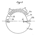
- FIG. 2 there is shown the disc 23 a which is part of the optical encoder 23 and which cooperates with a sensor 23 b , known in itself.
- This disc has a plurality of slots 32,33,34 and a notch 35.
- the sensor 23 b emits a pulse on the passage of each slot. This pulse increments the counter 22 a of the converter 22 during the suction stroke of the pump and resets this counter to zero during the reverse stroke, as explained above.
- the rotation of the disc 23 a during the suction stroke is indicated by the arrow A in FIG. 2.
- the spacing of the slots defined by the angle at the center between two successive slots will depend on the sensitivity of the adjustment that we want to give to the pump, and will have to satisfy the sinusoidal function which governs the stroke of the connecting rod head. depending on the angle of rotation of the crankshaft sleeve.
- the eccentricity of the sleeve is at least ten times less than the length of the connecting rod, the angular spacing of the slots on the disc responds to a function of the arc-sine type of each fraction of the desired stroke.
- the sensitivity of the adjustment finds a limit due to the operation of the triacs. Indeed, it is known that these become blocking in the absence of excitation of the light-emitting diode and at the passage of the supply current to zero. Thus a triac does not cut the power supply which it controls at the latest 10 milliseconds after the extinction of the diode, for a current of frequency 50 Hz.
- the slot 33 is in turn distant from the adjacent slot 32 by twice the aforementioned angle (20 milliseconds) and the slot 34 is located relative to the slot 33 at three times this angle. Given their situation with respect to rear dead center (P MAR), the error made with respect to the theoretical race is extremely small. It will be noted that the slot 34 which corresponds to 100% of the travel, is distant from the rear dead center by 10 milliseconds (in time) which correspond to a rest time required when switching the triacs.
- the notch 35 of the disc 23 a is such that when it moves opposite the sensor 23 b , no pulse is transmitted to the counter 22 a .
- the latter can therefore count the pulses corresponding to the frequency of the network during the return stroke of the moving assembly.
- the operation of the device according to the invention operates as follows. It will first be assumed that the pump operates independently as a function of the set values displayed by means of the members 20 and 29.
- the first pulse emitted by the timer 28 reaches the logic circuit 24 which excites the diode 14.
- the motor is powered to turn in one direction. It quickly hooks up its synchronism speed (generally within the first half-period of the supply current).
- the disc 23 a rotates in the direction A and the encoder 23 emits pulses in the direction of the counter 22 a and converter 22, until obtaining an equality noted by the comparator 21 which by its output signal imposes on the circuit 24, of a on the one hand, to interrupt the excitation of the diode 14, and on the other hand after a time delay of the order of 10 milliseconds to excite the diode 15.
- the triac 13 having turned on, the motor turns in the opposite direction .
- the circuit 24 by an incorporated control logic places the counter-converter unit 22, 22 a in a state in which the counter can count the pulses received at input 25 and corresponding to the frequency of the rectified sector, while that it is, on each pulse, emitted by the encoder 23, reset to zero.
- the disc 23 a rotates in the opposite direction to the direction A.
- the edge 35 a of the notch 35 is read as a slot and places the counter 22 a at zero.
- the latter then counts the half-periods of the network current until obtaining a number equal to that determined which it has on deposit at the time of construction (for example 6).
- the converter at this time emits a signal for the circuit 24 which interrupts the excitation of the diode 15.
- the motor will stop at the end of the next half-period and the disc will be in the position of FIG. 2 which corresponds, if so chosen in neutral before the moving part. It is understood that this position is repeatedly reached at the end of each return stroke of the moving assembly. It is an extremely reliable home position.
- FIG. 1 shows by reference 18 the supply to the comparator 21 of a setpoint signal (current or voltage) which, as an alternative to that set by the potentiometer 20, makes it possible to control the length of the stroke at this value variable set point.
- the electronic member 18 is used to filter, shape and on a scale compatible with the comparator 21, in particular by adjusting the zero and the gain of this member, a current or a voltage coming from a sensor (pH, flow rate, viscosity ...) or a regulator depending on whether you want to achieve an open loop or closed loop control. Putting this servo-control into service by switching off the potentiometer 20 by opening a switch 19 which can be carried out mechanically when a plug-in connector is put in place.
- control unit 17 and the opto-coupled triacs for controlling the supply of the motor can be grouped together in the same housing.
- the pump may then have only plug-in connection sockets at the level of the motor windings and at the level of the encoder 23.
- Two connection cables may suffice, on the one hand, to connect the encoder to the housing and, on the other hand, to supply the engine from the control box via the triacs.
- the pump is then simply supplied by the mains current supplied to the terminals of the motor windings, and operates like an ordinary pump at a fixed flow rate (its maximum flow rate), the crankshaft rotating in a continuous movement.
- the pump provided with the optical encoder can be connected to a programmable controller or a computer or a microprocessor with interface electronics comprising the opto-coupled triacs or static relays, in which the electronic circuit 24 and the control logic would be replaced by a program comprising control instructions as a function of the signals received and the set values.
- the invention finds an interesting application in the field of metering pumps.
Abstract
Description
Dans le brevet français 2 588 319, on a décrit un procédé permettant d'obtenir un réglage précis du débit d'une pompe doseuse en agissant sur trois paramètres de l'alimentation électrique d'un moteur synchrone réversible, à savoir l'enroulement auquel elle est appliquée déterminant ainsi le sens de rotation du moteur, le temps pendant lequel elle est appliquée déterminant la longueur de la demi-course de l'organe de pompage et le temps total d'un cycle aller-retour de cet organe déterminant la cadence de la pompe. Dans ce procédé,il est fait usage d'un microprocesseur qui, à partir d'une donnée d'entrée correspondant au débit désiré exprimé en fraction du débit maximal de la pompe, ou de deux données d'entrée correspondant à la course et la cadence désirées, procède à la sélection des paramètres utiles à la commande du moteur parmi des valeurs qu'il comporte en mémoire et gère la commande de ce moteur en fonction des paramètres sélectionnés.In French patent 2,588,319, a method has been described which makes it possible to obtain a precise adjustment of the flow rate of a metering pump by acting on three parameters of the electrical supply of a reversible synchronous motor, namely the winding at which it is applied thus determining the direction of rotation of the motor, the time during which it is applied determining the length of the half-stroke of the pumping member and the total time of a round-trip cycle of this member determining the rate of the pump. In this process, use is made of a microprocessor which, from an input data corresponding to the desired flow expressed as a fraction of the maximum flow of the pump, or from two input data corresponding to the stroke and the desired cadence, proceeds to the selection of parameters useful for controlling the motor from among the values it contains in memory and manages the control of this motor as a function of the parameters selected.
On s'est rendu compte que le procédé décrit convient à des pompes de haut de gamme, car les valeurs mémorisées dans le microprocesseur impliquent de la part de ces pompes un fonctionnement possédant très peu de disparité d'une pompe à l'autre, donc une fabrication de série très soignée pour tenir la précision désirée qui est inférieure à 1 %.We have realized that the process described is suitable for high-end pumps, because the values memorized in the microprocessor imply on the part of these pumps an operation having very little disparity from one pump to another, therefore very careful mass production to maintain the desired precision, which is less than 1%.
Il existe par ailleurs des pompes doseuses moins sophistiquées dans lesquelles le réglage du débit s'opère d'une part, par réglage de la cadence de la pompe au moyen d'une régulation électronique et, d'autre part, par réglage de la course en agissant mécaniquement sur les éléments de la chaîne de transmission, au moyen de butées au déplacement des organes de transmission ou de servo-moteurs pour l'entraînement de ces organes.There are also less sophisticated metering pumps in which the adjustment of the flow rate takes place on the one hand, by adjusting the rate of the pump by means of an electronic regulation and, on the other hand, by adjusting the stroke. by acting mechanically on the elements of the transmission chain, by means of stops for movement of the transmission members or of servo-motors for driving these members.
La présente invention entend étendre les avantages d'un réglage de débit qui n'intervient pas sur les éléments mécaniques par le biais d'organes limiteurs de course dont l'ajustement est toujours délicat et sujet à déréglage, ou par la mise en oeuvre de servo-moteurs, en mettant en oeuvre des moyens simplifiés par rapport aux moyens décrits dans le brevet français rappelé ci-dessus.The present invention intends to extend the advantages of a flow control which does not intervene on the mechanical elements by means of stroke limiting members. the adjustment of which is always delicate and subject to adjustment, or by the use of servomotors, by implementing means which are simplified compared to the means described in the French patent mentioned above.
A cet effet, l'invention a donc pour objet un dispositif de réglage du débit d'une pompe doseuse comportant un organe de pompage attelé à un organe de transmission convertissant le mouvement rotatif d'un moteur d'entraînement réversible en un mouvement alternatif de l'organe de pompage, comprenant des moyens de réglage de l'amplitude du mouvement alternatif et des moyens de réglage de la période de ce mouvement.To this end, the invention therefore relates to a device for adjusting the flow rate of a metering pump comprising a pumping member coupled to a transmission member converting the rotary movement of a reversible drive motor into an alternating movement of the pumping member, comprising means for adjusting the amplitude of the reciprocating movement and means for adjusting the period of this movement.
Selon une caractéristique importante de l'invention, les moyens de réglage de l'amplitude du mouvement alternatif comprennent :
- un capteur du déplacement de l'organe de transmission, émettant une pluralité d'impulsions dont le nombre est converti en une valeur analogique fonction de la valeur de l'amplitude du déplacement,
- un comparateur de ladite valeur analogique à une valeur de consigne réglable émettant en sortie un signal lorsque les valeurs comparées sont égales,
- un circuit électronique de commande recevant en entrée le signal émis par le comparateur, qui en réponse à ce signal d'une part commute l'alimentation du moteur pour inverser son sens de rotation et, d'autre part, active des moyens de détection du retour de l'organe de transmission à une position origine,
- ces moyens de détection émettant en direction du circuit électronique un signal lorsque la position-origine est atteinte, en réponse auquel le circuit logique commande l'interruption de l'alimentation du moteur, tandis que les moyens de réglage de la période du mouvement sont constituées par un émetteur d'impulsions en direction du circuit électronique, en réponse auxquelles ce dernier établit l'alimentation du moteur pour éloigner l'organe de transmission de ladite position d'origine.According to an important characteristic of the invention, the means for adjusting the amplitude of the reciprocating movement comprise:
a sensor for the displacement of the transmission member, emitting a plurality of pulses, the number of which is converted into an analog value as a function of the value of the amplitude of the displacement,
- a comparator of said analog value to an adjustable setpoint outputting a signal when the compared values are equal,
- an electronic control circuit receiving as input the signal emitted by the comparator, which in response to this signal on the one hand switches the power supply to the motor to reverse its direction of rotation and, on the other hand, activates detection means the return of the transmission member to an original position,
these detection means emitting towards the electronic circuit a signal when the original position is reached, in response to which the logic circuit controls the interruption of the power supply to the motor, while the means for adjusting the period of movement are constituted by a pulse transmitter in the direction of the electronic circuit, in response to which the latter establishes the supply of the engine to move the transmission member away from said original position.
Dans un mode de réalisation de l'invention, le capteur du déplacement de l'organe de transmission est constitué par un codeur optique calé en rotation sur un élément tournant de l'organe de transmission entraîné par le moteur.In one embodiment of the invention, the sensor for the displacement of the transmission member is constituted by an optical encoder locked in rotation on a rotary element of the transmission member driven by the motor.
Par ailleurs, les moyens de détection de la position-origine sont constitués par un compteur des impulsions du courant alternatif d'alimentation du moteur, remis à zéro à chaque impulsion émise par le codeur optique, ce dernier possédant une plage inactive au voisinage de la position-origine dans laquelle aucune impulsion n'est émise, le compteur émettant un signal en direction du circuit électronique lorsque les impulsions comptées sont égales à une valeur de consigne.Furthermore, the means for detecting the original position are constituted by a counter for the pulses of the alternating current supplying the motor, reset to zero at each pulse emitted by the optical encoder, the latter having an inactive range in the vicinity of the origin position in which no pulse is emitted, the counter emitting a signal towards the electronic circuit when the pulses counted are equal to a set value.
Le circuit logique peut être connecté à un émetteur d'impulsions interne, ce qui permet de régler le débit de la pompe de manière absolue, ou peut être connecté à un émetteur d'impulsions externe, ce qui permet d'asservir le débit de la pompe à une autre grandeur par exemple le débit du fluide de la canalisation principale dans laquelle les doses sont injectées, l'émetteur d'impulsions externe étant alors un débit-mètre. Une prise permet de sélectionner l'un ou l'autre des émetteurs, l'émetteur externe étant raccordable à l'appareil par un connecteur enfichable.The logic circuit can be connected to an internal pulse transmitter, which makes it possible to regulate the pump flow in an absolute manner, or can be connected to an external pulse transmitter, which allows to control the flow of the pump to another quantity, for example the flow rate of the fluid in the main pipe into which the doses are injected, the external pulse emitter then being a flow meter. A socket is used to select one or other of the transmitters, the external transmitter being connectable to the device by a plug-in connector.
L'invention sera mieux comprise au cours de la description donnée ci-après à titre d'exemple purement indicatif et non limitatif qui permettra d'en dégager les avantages et les caractéristiques secondaires.The invention will be better understood during the description given below by way of purely indicative and nonlimiting example which will make it possible to identify the advantages and the secondary characteristics thereof.
Il sera fait référence aux dessins annexés dans lesquels :
- - la figure 1 est un schéma d'un mode de réalisation de l'invention,
- - la figure 2 est un schéma de détail du codeur optique mis en oeuvre dans l'invention.
- FIG. 1 is a diagram of an embodiment of the invention,
- - Figure 2 is a detailed diagram of the optical encoder used in the invention.
En se reportant tout d'abord à la figure 1, on voit, schématiquement représenté, un moteur 1 réversible et synchrone, d'entraînement au moyen d'un réducteur 2,3 d'un vilebrequin 4 maintenu tournant dans des paliers 5 et 6 d'un bâti 7. Le manchon du vilebrequin porte le pied 8 d'une bielle d'actionnement d'un organe de pompage non représenté, qui peut être un piston ou une membrane.Referring first to Figure 1, we see, schematically shown, a reversible and synchronous motor 1, driving by means of a reduction gear 2.3 of a crankshaft 4 kept rotating in
Un entraînement en continu du vilebrequin à une vitesse de rotation donnée, imposée par la vitesse de rotation du moteur d'entraînement et du rapport de réduction du réducteur 2,3 engendre le débit maximum de la pompe.Continuous drive of the crankshaft at a given rotational speed, imposed by the rotational speed of the drive motor and the reduction ratio of the
On sait que pour délivrer une fraction de ce débit maximal, il faut rendre discontinu et alternatif le mouvement rotatif d'entraînement du vilebrequin pour pouvoir agir et sur la course de la tête 8 de bielle et sur la cadence de pompage.It is known that in order to deliver a fraction of this maximum flow rate, the rotary drive movement of the crankshaft must be made discontinuous and alternative in order to be able to act both on the stroke of the connecting rod head 8 and on the pumping rate.
Pour ce faire, dans le cas où le moteur 1 est un moteur synchrone réversible possédant deux enroulements 9a et 9b on prévoit un dispositif de commande de l'alimentation de ces enroulements de la manière suivante.To do this, in the case where the motor 1 is a reversible synchronous motor having two
Le point commun de ces enroulements est connecté à une borne 10 d'alimentation alternative de fréquence connue (par exemple 50Hz). Chacun des enroulements est également relié à l'autre borne 11 de cette source par l'intermédiaire d'un triac 12,13 optocouplé à une diode électroluminescente 14,15 qui en constitue l'organe de commande. Un condensateur 16 est disposé de manière connue entre les deux enroulements 9a et 9b. Lorsque le triac 12 est rendu conducteur, les enroulements sont alimentés l'un 9a par la tension du secteur et l'autre 9b par une tension déphasée du fait du condensateur, engendrant la rotation du vilebrequin dans un premier sens de rotation. L'inversion de sens de rotation est obtenue par la commutation de l'alimentation, le triac 12 n'étant plus passant alors que le triac 13 est rendu conducteur. L'excitation des diodes 14 et 15 est réalisée par une unité de commande 17 en fonction des différentes phases d'alimentation du moteur 1 que l'on désire réaliser pour obtenir le débit souhaité de la pompe.The common point of these windings is connected to an
Cette unité de commande 17 comporte tout d'abord des moyens de réglage de la course de l'équipage mobile. Ces moyens comportent un organe de sélection 20 d'une valeur de consigne correspondant à la course souhaitée de la bielle. Cette course pourra être exprimée en fraction (%) de la course totale au moyen d'un potentiomètre commandé manuellement délivrant une valeur analogique (tension) proportionnelle à la fraction désirée.This
Cette valeur de consigne est introduite dans un comparateur 21 qui reçoit également une tension variable engendrée par un convertisseur 22. Ce dernier reçoit en entrée les impulsions délivrées par un codeur optique 23. Le nombre de ces impulsions est en relation avec la course angulaire d'un disque 23a appartenant au codeur et dont il sera donné une description plus précise en regard de la figure 2. Ce disque 23a est solidaire de la roue 3 du réducteur 2,3 elle-même calée en rotation sur le vilebrequin 4.This set value is introduced into a
Un codeur optique d'un autre type pourrait être mis en oeuvre dans ce dispositif. Il pourrait notamment s'agir d'un capteur de déplacement de la bielle ou de l'organe de pompage, émettant une valeur analogique ou numérique convertie pour être comparée avec la valeur de consigne.An optical encoder of another type could be used in this device. It could in particular be a displacement sensor of the connecting rod or of the pumping member, emitting an analog or digital value converted to be compared with the set value.
Lorsque l'égalité est constatée par le comparateur 21, un signal est émis en sortie du comparateur en direction d'un circuit électronique de commande 24 qui, en réponse, commande l'extinction de la diode 14 et, après un temps de repos très court, l'excitation de la diode 15. L'alimentation du moteur 1 est alors commutée et ce dernier tourne en sens contraire.When equality is noted by the
Dans le même temps, le circuit électronique 24 par l'intermédiaire d'une logique de commande qu'il possède, active un compteur 22a appartenant au convertisseur 22. La logique de commande reçoit alors en entrée 25 des impulsions correspondant à la fréquence du courant alternatif d'alimentation du réseau (en fait, à la fréquence de 100 Hz compte tenu du pont de diodes 26 et de la diode 26a) et dirige ces impulsions du secteur vers le compteur 22a du convertisseur 22 .Ce compteur est remis à zéro par chacune des impulsions émises par le codeur optique 23 tournant en sens inverse. Le codeur optique possède une plage angulaire définie par rapport à une position du vilebrequin (par exemple au voisinage de sa position correspondant au point mort avant de l'organe de pompage), pendant laquelle il n'émet plus d'impulsion. Le compteur 22a n'étant alors plus remis à zéro compte les impulsions qu'il reçoit en entrée jusqu'à avoir atteint un nombre correspondant à une valeur de consigne déterminée. A ce moment, le convertisseur 22 délivre un signal en direction du circuit électronique 24 qui, en réponse, commande l'extinction de la diode 15. Le moteur s'arrête et l'équipage mobile est dans une position dite position-origine (par exemple le point mort avant).At the same time, the
On voit qu'ainsi l'équipage mobile s'arrête toujours à la fin de sa course de retour, dans une position fixe déterminée.It can be seen that in this way the mobile team always stops at the end of its return stroke, in a fixed fixed position.
Le démarrage d'un nouveau cycle de pompage est commandé par le circuit 24 qui excite la diode 14 en réponse à un signal qu'il reçoit sur l'une des deux entrées 27a et 27b. L'entrée 27a est reliée à la sortie d'un générateur d'impulsions 28 dont la fréquence peut être manuellement réglée au moyen, par exemple d'un potentiomètre 29, intégré dans un circuit de type RC. Ce générateur peut être de tout type connu et comporter, s'il est numérique, des moyens d'horloge indépendants. En réglant la fréquence de ces impulsions on règle le temps de cycle.The start of a new pumping cycle is controlled by the
En alternative, le circuit 24 peut recevoir sur son entrée 27b des impulsions émises par un générateur extérieur (par exemple un débit-mètre). Dans ces conditions la cadence de la pompe et, pour une course donnée, son débit, peuvent être asservis à un paramètre extérieur du type débit de circulation du fluide dans lequel les doses sont introduites. Ce générateur extérieur peut être connecté à l'appareil par un cordon enfichable en 30, et cette connexion a pour effet la commande d'un commutateur 31 qui isole le circuit 24 du cadenceur interne 28.Alternatively, the
Sur la figure 2 on a représenté le disque 23a qui fait partie du codeur optique 23 et qui coopère avec un capteur 23b, connu en lui-même. Ce disque comporte une pluralité de fentes 32,33,34 et une encoche 35.In Figure 2 there is shown the
Schématiquement, le capteur 23b émet une impulsion au passage de chaque fente. Cette impulsion incrémente le compteur 22 a du convertisseur 22 lors de la course d'aspiration de la pompe et remet ce compteur à zéro lors de la course inverse, comme expliqué ci-dessus. La rotation du disque 23a lors de la course d'aspiration est indiquée par la flèche A sur la figure 2.Schematically, the
L'espacement des fentes défini par l'angle au centre entre deux fentes successives, sera fonction de la sensibilité du réglage que l'on veut donner à la pompe, et devra satisfaire la fonction sinusoïdale qui régit la course de la tête de bielle en fonction de l'angle de rotation du manchon du vilebrequin. Dans la pratique, comme l'excentricité du manchon est au moins dix fois inférieure à la longueur de la bielle, l'espacement angulaire des fentes sur le disque répond à une fonction du type arc-sinus de chaque fraction de course désirée.The spacing of the slots defined by the angle at the center between two successive slots, will depend on the sensitivity of the adjustment that we want to give to the pump, and will have to satisfy the sinusoidal function which governs the stroke of the connecting rod head. depending on the angle of rotation of the crankshaft sleeve. In practice, since the eccentricity of the sleeve is at least ten times less than the length of the connecting rod, the angular spacing of the slots on the disc responds to a function of the arc-sine type of each fraction of the desired stroke.
La sensibilité du réglage trouve une limite due au fonctionnement des triacs. En effet, on sait que ceux-ci deviennent bloquant en l'absence d'excitation de la diode électroluminescente et au passage à zéro du courant d'alimentation. Ainsi un triac ne coupe l'alimentation qu'il contrôle au plus tard 10 millisecondes après l'extinction de la diode, pour un courant de fréquence 50 Hz.The sensitivity of the adjustment finds a limit due to the operation of the triacs. Indeed, it is known that these become blocking in the absence of excitation of the light-emitting diode and at the passage of the supply current to zero. Thus a triac does not cut the power supply which it controls at the latest 10 milliseconds after the extinction of the diode, for a current of frequency 50 Hz.
Ces 10 millisecondes correspondent à un angle de rotation du vilebrequin qui, pour un moteur synchrone donné à la vitesse de synchronisme, sera d'autant plus grand que le rapport de réduction du réducteur 2,3 est petit, donc que le vilebrequin tourne vite. Par exemple, si l'on veut réaliser un réglage du débit de 5 en 5 % dans une pompe entraînée par un moteur synchrone dont la vitesse de synchronisme est de 375 tours par minute et le rapport de réduction de 3,5, 10 millisecondes correspondent à 6,43 degrés d'angle de rotation du vilebrequin. Or la fonction arc-sinus susdite donne pour 5 % de course une valeur angulaire entre deux fentes de l'ordre de 5,7 degrés d'angle après un quart de tour du vilebrequin à partir de l'un des points morts de l'équipage mobile.These 10 milliseconds correspond to an angle of rotation of the crankshaft which, for a synchronous motor given at the synchronism speed, will be all the greater as the reduction ratio of the
Si on constate, par exemple, qu'ayant affiché 45 % l'extinction de la diode du triac considéré coïncide avec la fin d'une demi-période du courant, il y aura effectivement égalité entre la course réelle et la course affichée. A 50 %, c'est-à-dire pour 5,7 degré d'angle supplémentaires, le triac fonctionnera encore pendant une course correspondant à 0,7 degrés d'angle, et la course réelle sera un peu supérieure à 50 %. En revanche, à 40 %, c'est-à-dire pour 5,8 degrés d'angle en moins, le triac ne deviendra bloquant qu'à la fin de la demi-période suivante, c'est-à-dire qu'en fait la course réelle correspondra à 45 % pour un affichage de 40%.If it is noted, for example, that having displayed 45% the extinction of the triac diode considered coincides with the end of a half-period of the current, there will be effectively equality between the real race and the displayed race. At 50%, i.e. for an additional 5.7 degrees of angle, the triac will still operate during a stroke corresponding to 0.7 degrees of angle, and the actual stroke will be a little more than 50%. On the other hand, at 40%, that is to say for 5.8 degrees less angle, the triac will only become blocking at the end of the following half-period, that is to say that 'in fact the actual stroke will correspond to 45% for a display of 40%.
Une solution pour pallier cet inconvénient consiste à rendre petit l'angle de rotation correspondant à 10 millisecondes, donc à diminuer la vitesse du vilebrequin en augmentant la démultiplication du réducteur, par rapport au plus petit angle d'espacement de deux fentes du disque. Cette solution conviendrait pour des pompes de grandes cylinrées à mouvement lent.One solution to overcome this drawback consists in making the rotation angle small corresponding to 10 milliseconds, therefore in reducing the speed of the crankshaft by increasing the reduction ratio of the reduction gear, compared to the smallest angle of spacing of two slots of the disc. This solution would be suitable for large displacement pumps with slow movement.
Pour des pompes plus rapides, une autre solution consiste à répartir les fentes avec entre elles un angle au centre correspondant à l'angle - ou un multiple de celui-ci - parcouru par le vilebrequin à la vitesse de synchronisme du moteur. Ainsi, sur la figure 2 les fentes 32 sont espacées les unes des autres d'un angle égal correspondant à l'angle parcouru en 10 millisecondes par le vilebrequin 4 entraîné par le moteur et le réducteur de l'exemple ci-dessus. En affectant à la fente voisine de l'encoche 35 la valeur 15 % et à celle voisine de la fente 33 la valeur 90 %, on commet une erreur absolue d'affichage par rapport à la course théorique au plus égale à environ 1,7 % en excès ou en défaut. La fente 33 est quant à elle distante de la fente adjacente 32 du double de l'angle susdit (20 millisecondes) et la fente 34 est située par rapport à la fente 33 au triple de cet angle. Compte tenu de leur situation par rapport au point mort arrière (P MAR),l'erreur commise par rapport à la course théorique est extrêmement faible. On notera que la fente 34 qui correspond à 100 % de la course, est distante du point mort arrière de 10 millisecondes (en temps) qui correspondent à un temps de repos nécessaire lors de la commutation des triacs.For faster pumps, another solution consists in distributing the slots with an angle between them corresponding to the angle - or a multiple thereof - traversed by the crankshaft at the speed of synchronization of the engine. Thus, in Figure 2 the
L'encoche 35 du disque 23a est telle que lorsqu'elle se déplace en regard du capteur 23b, aucune impulsion n'est transmise au compteur 22a. Ce dernier, comme dit plus haut, peut donc compter les impulsions correspondant à la fréquence du réseau lors de la course de retour de l'équipage mobile.The
Le fonctionnement du dispositif selon l'invention s'opère de la manière suivante. On supposera tout d'abord que la pompe fonctionne de manière indépendante en fonction de valeurs de consigne affichée au moyen des organes 20 et 29.The operation of the device according to the invention operates as follows. It will first be assumed that the pump operates independently as a function of the set values displayed by means of the
La première impulsion émise par le cadenceur 28 parvient au circuit logique 24 qui excite la diode 14. Le moteur est alimenté pour tourner dans un sens. Il accroche rapidement sa vitesse de synchronisme (en général à l'intérieur de la première demi-période du courant d'alimentation). Le disque 23a tourne dans le sens A et le codeur 23 émet des impulsions en direction des compteur 22a et convertisseur 22, jusqu'à l'obtention d'une égalité constatée par le comparateur 21 qui par son signal de sortie impose au circuit 24, d'une part, d'interrompre l'excitation de la diode 14, et d'autre part au bout d'une temporisation de l'ordre de 10 millisecondes d'exciter la diode 15. Le triac 13 devenu passant, le moteur tourne en sens inverse. Dans le même temps, le circuit 24 par une logique de commande incorporée place l'ensemble compteur-convertisseur 22, 22a dans un état dans lequel le compteur peut compter les impulsions reçues en entrée 25 et correspondant à la fréquence du secteur redressée, tandis qu'il est, à chaque impulsion, émise par le codeur 23, remis à zéro. Le disque 23a tourne en sens inverse du sens A. Le bord 35a de l'encoche 35 est lu comme une fente et place le compteur 22a à zéro. Ce dernier compte alors les demi-périodes du courant du réseau jusqu'à obtenir un nombre égal à celui déterminé qu'il possède en consigne au moment de la construction (par exemple 6). Le convertisseur à ce moment émet un signal pour le circuit 24 qui interrompt l'excitation de la diode 15. Le moteur s'arrêtera à la fin de la demi-période suivante et le disque sera dans la position de la figure 2 qui correspond, si on l'a choisi ainsi au point mort avant de l'équipage mobile. On comprend que cette position est atteinte de manière répétitive à la fin de chaque course retour de l'équipage mobile. C'est une position-origine extrêmement fiable.The first pulse emitted by the
Un nouveau cycle sera commencé à la réception par le circuit 24 de la prochaine impulsion du cadenceur 28. On voit donc que pour une cadence donnée on peut agir sur le débit en agissant sur la course et que pour une course donnée on peut agir sur le débit en agissant sur la cadence, sachant que dans l'un comme l'autre des cas, le temps de cycle ne peut pas être inférieur au temps d'un aller et retour de l'équipage mobile.A new cycle will be started upon reception by
Pour asservir la pompe à, par exemple, un débit-mètre à impulsions, il suffit de brancher cet émetteur d'impulsions à l'unité de commande 17 par la prise de connexion 30 . Il ne restera alors plus qu'un seul moyen d'agir sur le débit : le réglage de la course. Le débit délivré sera proportionnel au débit principal avec un coefficient de proportionnalité réglable. Dans certains cas, il n'est pas possible d'asservir le débit de la pompe en agissant uniquement sur la cadence. Il faut pouvoir agir sur la valeur de la course, la viscosité du fluide par exemple, ne permettant que des cadences inférieures à un seuil déterminé. On a représenté sur la figure 1 par la référence 18 la fourniture au comparateur 21 d'un signal (courant ou tension) de consigne qui, en alternative de celui réglé par le potentiomètre 20, permet d'asservir la longueur de course à cette valeur de consigne variable. L'organe électronique 18 sert à filtrer, mettre en forme et à une échelle compatible avec le comparateur 21, en réglant notamment le zéro et le gain de cet organe, un courant ou une tension issu d'un capteur (pH, débit, viscosité...) ou d'un régulateur selon que l'on veut réaliser un asservissement en boucle ouverte ou en boucle fermée. La mise en service de cet asservissement par la course met hors circuit le potentiomètre 20 par l'ouverture d'un interrupteur 19 qui peut être réalisée mécaniquement lors de la mise en place d'un connecteur enfichable.To slave the pump to, for example, a pulse flow meter, it is sufficient to connect this pulse transmitter to the
L'un des avantages de la pompe selon l'invention réside dans le fait que l'on peut regrouper dans un même boîtier l'unité de commande 17 et les triacs opto-couplés de commande de l'alimentation du moteur. La pompe peut alors ne présenter que des prises de connexions enfichables au niveau des enroulements du moteur et au niveau du codeur 23. Deux câbles de liaison peuvent suffire pour, d'une part, relier le codeur au boîtier et d'autre part, alimenter le moteur depuis le boîtier de commande par l'intermédiaire des triacs. On peut, dans une version de ce type, placer le boîtier à distance de la pompe et même ne pas utiliser le boîtier. La pompe est alors simplement alimentée par le courant du réseau apporté aux bornes des enroulements du moteur, et fonctionne comme une pompe ordinaire à un débit fixe (son débit maximal), le vilebrequin tournant d'un mouvement continu.One of the advantages of the pump according to the invention lies in the fact that the
Enfin, dans une variante plus sophistiquée de l'invention, la pompe pourvue du codeur optique peut être connectée à un automate programmable ou un ordinateur ou un microprocesseur avec une électronique d'interface comportant les triacs opto-couplés ou des relais statiques, dans lesquels le circuit électronique 24 et les logiques de commande seraient remplacés par un programme comprenant des instructions de commande en fonction des signaux reçus et les valeurs de consignes.Finally, in a more sophisticated variant of the invention, the pump provided with the optical encoder can be connected to a programmable controller or a computer or a microprocessor with interface electronics comprising the opto-coupled triacs or static relays, in which the
L'invention trouve une application intéressante dans le domaine des pompes doseuses.The invention finds an interesting application in the field of metering pumps.
Claims (10)
- un capteur (23) du déplacement de l'organe de transmission (4), émettant une pluralité d'impulsions dont le nombre est converti en une valeur analogique fonction de la valeur de l'amplitude du déplacement,
- un comparateur (21) de ladite valeur analogique à une valeur de consigne réglable (20) émettant en sortie un signal lorsque les valeurs comparées sont égales,
- un circuit (24) électronique de commande recevant en entrée le signal émis par le comparateur (21), qui en réponse à ce signal, d'une part, commute l'alimentation du moteur (1) pour inverser son sens de rotation et, d'autre part, active des moyens de détection (22) du retour de l'organe de transmission à une position-origine,
- ces moyens de détection (22) émettant en direction du circuit électronique un signal lorsque la position-origine est atteinte, en réponse auquel le circuit électronique (24) commande l'interruption de l'alimentation du moteur (1), et en ce que les moyens de réglage de la période du mouvement sont constitués par un émetteur (28) d'impulsions en direction du circuit électronique (24), en réponse auxquelles ce dernier établit l'alimentation du moteur (1) pour éloigner l'organe de transmission (4) de ladite position-origine.1. Device for adjusting the flow rate of a metering pump comprising a pumping member (8) coupled to a transmission member (4) converting the rotary movement of a reversible drive motor (1) into an alternating movement of the pumping member, comprising means for adjusting the amplitude of the reciprocating movement and means for adjusting the period of this movement, characterized in that the means for adjusting the amplitude of the reciprocating movement comprise,
- a sensor (23) of the displacement of the transmission member (4), emitting a plurality of pulses, the number of which is converted into an analog value as a function of the value of the amplitude of the displacement,
- a comparator (21) of said analog value to an adjustable setpoint (20) outputting a signal when the compared values are equal,
- an electronic control circuit (24) receiving as input the signal emitted by the comparator (21), which in response to this signal, on the one hand, switches the power supply to the motor (1) to reverse its direction of rotation and , on the other hand, activates detection means (22) of the return of the transmission member to an original position,
- These detection means (22) emitting towards the electronic circuit a signal when the original position is reached, in response to which the electronic circuit (24) controls the interruption of the supply of the motor (1), and in this that the means for adjusting the period of the movement consist of a transmitter (28) of pulses in the direction of the electronic circuit (24), in response to which the latter establishes the supply of the motor (1) in order to distance the member from transmission (4) of said original position.
Priority Applications (1)
| Application Number | Priority Date | Filing Date | Title |
|---|---|---|---|
| AT88403176T ATE66725T1 (en) | 1987-12-17 | 1988-12-14 | FLOW RATE CONTROL DEVICE FOR AN ALTERNATE DOSING PUMP. |
Applications Claiming Priority (2)
| Application Number | Priority Date | Filing Date | Title |
|---|---|---|---|
| FR8717635A FR2624919B1 (en) | 1987-12-17 | 1987-12-17 | DEVICE FOR ADJUSTING THE FLOW OF AN ALTERNATIVE DOSING PUMP |
| FR8717635 | 1987-12-17 |
Publications (2)
| Publication Number | Publication Date |
|---|---|
| EP0321339A1 true EP0321339A1 (en) | 1989-06-21 |
| EP0321339B1 EP0321339B1 (en) | 1991-08-28 |
Family
ID=9357980
Family Applications (1)
| Application Number | Title | Priority Date | Filing Date |
|---|---|---|---|
| EP88403176A Expired - Lifetime EP0321339B1 (en) | 1987-12-17 | 1988-12-14 | Flow rate regulating system for an alternating dosing pump |
Country Status (9)
| Country | Link |
|---|---|
| US (1) | US4925371A (en) |
| EP (1) | EP0321339B1 (en) |
| JP (1) | JPH01280695A (en) |
| AT (1) | ATE66725T1 (en) |
| CA (1) | CA1303703C (en) |
| DE (2) | DE3864503D1 (en) |
| ES (1) | ES2009735B3 (en) |
| FR (1) | FR2624919B1 (en) |
| GR (2) | GR890300134T1 (en) |
Cited By (1)
| Publication number | Priority date | Publication date | Assignee | Title |
|---|---|---|---|---|
| WO1997003290A1 (en) * | 1995-07-13 | 1997-01-30 | Knf Flodos Ag | Dosing pump |
Families Citing this family (15)
| Publication number | Priority date | Publication date | Assignee | Title |
|---|---|---|---|---|
| US5131816A (en) * | 1988-07-08 | 1992-07-21 | I-Flow Corporation | Cartridge fed programmable ambulatory infusion pumps powered by DC electric motors |
| US5182826A (en) * | 1989-03-09 | 1993-02-02 | Ssi Medical Services, Inc. | Method of blower control |
| US5195873A (en) * | 1992-03-13 | 1993-03-23 | C.A.P., Inc. | Chemical transfer system |
| US5676525A (en) * | 1993-02-19 | 1997-10-14 | Neovation Ag | Vacuum limiting medical pump |
| DE10162773A1 (en) * | 2001-12-20 | 2003-07-10 | Knf Flodos Ag Sursee | metering |
| US20050287009A1 (en) | 2002-11-28 | 2005-12-29 | Tadashi Kukitome | Metered quantity transfer device |
| ATE365868T1 (en) * | 2004-06-04 | 2007-07-15 | Sonceboz Sa | PUMP DRIVE |
| US7275474B2 (en) * | 2005-05-31 | 2007-10-02 | Parker-Hannifincorporation | Optical position sensing and method |
| DE102009020412A1 (en) * | 2009-05-08 | 2010-11-18 | Lewa Gmbh | Method and device for mixing fluids |
| US8535026B2 (en) * | 2010-06-30 | 2013-09-17 | Schlumberger Technology Corporation | Mechanical system for movement along a housing axis |
| MX339953B (en) | 2011-07-28 | 2016-06-20 | Ecolab Inc | A diaphragm pump for dosing a fluid and an according method. |
| DE102012214385A1 (en) * | 2012-08-13 | 2014-02-13 | Zf Friedrichshafen Ag | Device for moving a piston of adjustable radial piston engine, has sensor device that is provided to determine amplitude of movement of piston based on the changing amplitude of scanning size |
| CN107387380A (en) * | 2016-05-14 | 2017-11-24 | 勇猛机械股份有限公司 | The control device of electronic pump in a kind of cropper |
| US10458402B2 (en) * | 2016-07-25 | 2019-10-29 | Xiamen Conjoin Electronics Technology Co., Ltd. | Micro water pump capable of controlling flow precisely |
| US10856668B2 (en) | 2017-04-10 | 2020-12-08 | Hill-Rom Services, Inc. | Mattress overlay control system with rotary valves and graphical user interface for percussion and vibration, turn assist and microclimate management |
Citations (6)
| Publication number | Priority date | Publication date | Assignee | Title |
|---|---|---|---|---|
| GB1176870A (en) * | 1967-11-07 | 1970-01-07 | English Electric Co Ltd | Motor Control System. |
| FR2331021A1 (en) * | 1975-11-10 | 1977-06-03 | Varian Associates | LIQUID PHASE CHROMATOGRAPHY SYSTEM WHERE THE PUMP INLET VALVE IS POSITIVELY DRIVEN |
| EP0025575A1 (en) * | 1979-09-13 | 1981-03-25 | Roche Diagnostics GmbH | Dosage device |
| FR2500081A1 (en) * | 1981-02-17 | 1982-08-20 | Hartmann & Laemmle | METERING PUMP |
| DE3301741A1 (en) * | 1983-01-20 | 1984-07-26 | Bosch Gmbh Robert | Fuel pump with pre-excitation by permanent magnet and controlled piston stroke |
| FR2588319A1 (en) * | 1985-10-04 | 1987-04-10 | Milton Roy Dosapro | PROCESS FOR PRECISELY ESTABLISHING THE FLOW RATE OF A METERING PUMP AND METERING PUMP USING THE SAME |
Family Cites Families (3)
| Publication number | Priority date | Publication date | Assignee | Title |
|---|---|---|---|---|
| US3985019A (en) * | 1975-11-10 | 1976-10-12 | Boehme Detlef R | Liquid chromatography system with solvent proportioning |
| FR2461126A1 (en) * | 1978-12-15 | 1981-01-30 | Gilson Medical Electronic Fran | PISTON PUMP WITH PRECISELY ADJUSTABLE FLOW |
| US4681513A (en) * | 1985-02-01 | 1987-07-21 | Jeol Ltd. | Two-stage pump assembly |
-
1987
- 1987-12-17 FR FR8717635A patent/FR2624919B1/en not_active Expired - Lifetime
-
1988
- 1988-12-14 DE DE8888403176T patent/DE3864503D1/en not_active Expired - Lifetime
- 1988-12-14 DE DE198888403176T patent/DE321339T1/en active Pending
- 1988-12-14 AT AT88403176T patent/ATE66725T1/en not_active IP Right Cessation
- 1988-12-14 ES ES88403176T patent/ES2009735B3/en not_active Expired - Lifetime
- 1988-12-14 EP EP88403176A patent/EP0321339B1/en not_active Expired - Lifetime
- 1988-12-14 US US07/284,630 patent/US4925371A/en not_active Expired - Fee Related
- 1988-12-16 JP JP63316543A patent/JPH01280695A/en active Pending
- 1988-12-16 CA CA000586116A patent/CA1303703C/en not_active Expired - Lifetime
-
1990
- 1990-01-19 GR GR89300134T patent/GR890300134T1/en unknown
-
1991
- 1991-11-07 GR GR91401684T patent/GR3003075T3/en unknown
Patent Citations (6)
| Publication number | Priority date | Publication date | Assignee | Title |
|---|---|---|---|---|
| GB1176870A (en) * | 1967-11-07 | 1970-01-07 | English Electric Co Ltd | Motor Control System. |
| FR2331021A1 (en) * | 1975-11-10 | 1977-06-03 | Varian Associates | LIQUID PHASE CHROMATOGRAPHY SYSTEM WHERE THE PUMP INLET VALVE IS POSITIVELY DRIVEN |
| EP0025575A1 (en) * | 1979-09-13 | 1981-03-25 | Roche Diagnostics GmbH | Dosage device |
| FR2500081A1 (en) * | 1981-02-17 | 1982-08-20 | Hartmann & Laemmle | METERING PUMP |
| DE3301741A1 (en) * | 1983-01-20 | 1984-07-26 | Bosch Gmbh Robert | Fuel pump with pre-excitation by permanent magnet and controlled piston stroke |
| FR2588319A1 (en) * | 1985-10-04 | 1987-04-10 | Milton Roy Dosapro | PROCESS FOR PRECISELY ESTABLISHING THE FLOW RATE OF A METERING PUMP AND METERING PUMP USING THE SAME |
Cited By (2)
| Publication number | Priority date | Publication date | Assignee | Title |
|---|---|---|---|---|
| WO1997003290A1 (en) * | 1995-07-13 | 1997-01-30 | Knf Flodos Ag | Dosing pump |
| US5971723A (en) * | 1995-07-13 | 1999-10-26 | Knf Flodos Ag | Dosing pump |
Also Published As
| Publication number | Publication date |
|---|---|
| EP0321339B1 (en) | 1991-08-28 |
| FR2624919B1 (en) | 1990-04-27 |
| ES2009735B3 (en) | 1992-03-16 |
| ATE66725T1 (en) | 1991-09-15 |
| CA1303703C (en) | 1992-06-16 |
| JPH01280695A (en) | 1989-11-10 |
| ES2009735A4 (en) | 1989-10-16 |
| DE321339T1 (en) | 1989-11-16 |
| US4925371A (en) | 1990-05-15 |
| DE3864503D1 (en) | 1991-10-02 |
| FR2624919A1 (en) | 1989-06-23 |
| GR3003075T3 (en) | 1993-02-17 |
| GR890300134T1 (en) | 1990-01-19 |
Similar Documents
| Publication | Publication Date | Title |
|---|---|---|
| EP0321339B1 (en) | Flow rate regulating system for an alternating dosing pump | |
| EP0223643B1 (en) | Process to define exactly the flow rate of a dosing pump, and such a pump | |
| EP0363264B1 (en) | Synchronous motor whose sense of rotation can be selected | |
| FR2575514A1 (en) | CONTROL SYSTEM FOR AN AUTOMATIC DOOR | |
| FR2461126A1 (en) | PISTON PUMP WITH PRECISELY ADJUSTABLE FLOW | |
| FR2540308A1 (en) | METHOD AND SYSTEM FOR CONTROLLING AN ELECTRONIC SWITCH MOTOR | |
| EP1376056A1 (en) | Modular system for generating a reference plane using laser | |
| FR2478021A1 (en) | CONTROL DEVICE FOR AIRCRAFT ALLOWING AUTOMATIC / MANUAL SWITCHING INSTANTLY | |
| FR2718544A1 (en) | Device for positioning an adjusting element having a plurality of stable positions. | |
| FR2920287A1 (en) | PROCESS FOR MEASURING THE QUANTITY OF COFFEE DISTRIBUTED BY A COFFEE MILL AND APPARATUS COMPRISING SUCH A MILL | |
| EP1675253A2 (en) | Method for the operation of a home automation network comprising an actuator and a control unit | |
| FR2485292A1 (en) | ELECTROMECHANICAL ENERGY CONVERSION ASSEMBLY WITH BRUSHLESS MACHINE AND ITS CONTROL METHOD | |
| EP0478430B1 (en) | Friction jack | |
| FR2788175A1 (en) | STEPPING MOTOR CONTROL | |
| FR2628286A1 (en) | HARVESTING COUNTER FOR COMBINE HARVESTER | |
| EP2172143B1 (en) | Method for controlling the movement of a component of an electrical household appliance, in particular a control panel of a baking oven | |
| EP0054446A1 (en) | Electric asynchronous motor, means for controlling the feeding of such a motor and circulating drive comprising such a motor | |
| FR2864723A1 (en) | CONTROL DEVICE FOR AN ELECTRIC GENERATOR OF A MOTOR VEHICLE | |
| FR2638861A1 (en) | PROGRAMMER, IN PARTICULAR FOR HOUSEHOLD APPLIANCE | |
| FR2972409A1 (en) | METHOD AND DEVICE FOR CONTROLLING AN ELECTRIC WIPER MOTOR | |
| FR3079177A1 (en) | ELECTRIC MOTOR LIGHTING CORRECTION DEVICE WITH CONTINUOUS CURRENT FOR MOTOR VEHICLE. | |
| BE1011536A3 (en) | CONTROL METHOD FOR gripper. | |
| EP0401449A1 (en) | Dispensing and metering device for washing or cleaning machines | |
| FR2606229A1 (en) | System for controlling a single-phase asynchronous motor intended for driving an object such as a blind of the type with orientable slats | |
| FR3110305A1 (en) | ROTATING TOOL BRAKING DEVICE IN A CULINARY PREPARATION EQUIPMENT |
Legal Events
| Date | Code | Title | Description |
|---|---|---|---|
| PUAI | Public reference made under article 153(3) epc to a published international application that has entered the european phase |
Free format text: ORIGINAL CODE: 0009012 |
|
| 17P | Request for examination filed |
Effective date: 19881215 |
|
| AK | Designated contracting states |
Kind code of ref document: A1 Designated state(s): AT BE CH DE ES GB GR IT LI LU NL SE |
|
| ITCL | It: translation for ep claims filed |
Representative=s name: INGG. GUZZI RAVIZZA |
|
| GBC | Gb: translation of claims filed (gb section 78(7)/1977) | ||
| TCAT | At: translation of patent claims filed | ||
| TCNL | Nl: translation of patent claims filed | ||
| DET | De: translation of patent claims | ||
| 17Q | First examination report despatched |
Effective date: 19900724 |
|
| GRAA | (expected) grant |
Free format text: ORIGINAL CODE: 0009210 |
|
| AK | Designated contracting states |
Kind code of ref document: B1 Designated state(s): AT BE CH DE ES GB GR IT LI LU NL SE |
|
| REF | Corresponds to: |
Ref document number: 66725 Country of ref document: AT Date of ref document: 19910915 Kind code of ref document: T |
|
| REF | Corresponds to: |
Ref document number: 3864503 Country of ref document: DE Date of ref document: 19911002 |
|
| ITF | It: translation for a ep patent filed |
Owner name: GUZZI E RAVIZZA S.R.L. |
|
| GBT | Gb: translation of ep patent filed (gb section 77(6)(a)/1977) | ||
| PGFP | Annual fee paid to national office [announced via postgrant information from national office to epo] |
Ref country code: LU Payment date: 19911204 Year of fee payment: 4 |
|
| PGFP | Annual fee paid to national office [announced via postgrant information from national office to epo] |
Ref country code: CH Payment date: 19911206 Year of fee payment: 4 |
|
| PGFP | Annual fee paid to national office [announced via postgrant information from national office to epo] |
Ref country code: SE Payment date: 19911216 Year of fee payment: 4 |
|
| PGFP | Annual fee paid to national office [announced via postgrant information from national office to epo] |
Ref country code: AT Payment date: 19911227 Year of fee payment: 4 |
|
| PGFP | Annual fee paid to national office [announced via postgrant information from national office to epo] |
Ref country code: GR Payment date: 19911230 Year of fee payment: 4 |
|
| PGFP | Annual fee paid to national office [announced via postgrant information from national office to epo] |
Ref country code: NL Payment date: 19911231 Year of fee payment: 4 |
|
| PGFP | Annual fee paid to national office [announced via postgrant information from national office to epo] |
Ref country code: BE Payment date: 19920102 Year of fee payment: 4 |
|
| REG | Reference to a national code |
Ref country code: ES Ref legal event code: FG2A Ref document number: 2009735 Country of ref document: ES Kind code of ref document: B3 |
|
| EPTA | Lu: last paid annual fee | ||
| PLBE | No opposition filed within time limit |
Free format text: ORIGINAL CODE: 0009261 |
|
| STAA | Information on the status of an ep patent application or granted ep patent |
Free format text: STATUS: NO OPPOSITION FILED WITHIN TIME LIMIT |
|
| 26N | No opposition filed | ||
| REG | Reference to a national code |
Ref country code: GR Ref legal event code: FG4A Free format text: 3003075 |
|
| PG25 | Lapsed in a contracting state [announced via postgrant information from national office to epo] |
Ref country code: LU Free format text: LAPSE BECAUSE OF NON-PAYMENT OF DUE FEES Effective date: 19921214 Ref country code: AT Effective date: 19921214 |
|
| PG25 | Lapsed in a contracting state [announced via postgrant information from national office to epo] |
Ref country code: SE Effective date: 19921215 |
|
| PG25 | Lapsed in a contracting state [announced via postgrant information from national office to epo] |
Ref country code: LI Effective date: 19921231 Ref country code: CH Effective date: 19921231 Ref country code: BE Effective date: 19921231 |
|
| BERE | Be: lapsed |
Owner name: DOSAPRO MILTON ROY Effective date: 19921231 |
|
| PG25 | Lapsed in a contracting state [announced via postgrant information from national office to epo] |
Ref country code: GR Free format text: THE PATENT HAS BEEN ANNULLED BY A DECISION OF A NATIONAL AUTHORITY Effective date: 19930630 |
|
| PG25 | Lapsed in a contracting state [announced via postgrant information from national office to epo] |
Ref country code: NL Effective date: 19930701 |
|
| NLV4 | Nl: lapsed or anulled due to non-payment of the annual fee | ||
| REG | Reference to a national code |
Ref country code: CH Ref legal event code: PL |
|
| PGFP | Annual fee paid to national office [announced via postgrant information from national office to epo] |
Ref country code: GB Payment date: 19931129 Year of fee payment: 6 |
|
| PGFP | Annual fee paid to national office [announced via postgrant information from national office to epo] |
Ref country code: ES Payment date: 19931210 Year of fee payment: 6 |
|
| PGFP | Annual fee paid to national office [announced via postgrant information from national office to epo] |
Ref country code: DE Payment date: 19940128 Year of fee payment: 6 |
|
| PG25 | Lapsed in a contracting state [announced via postgrant information from national office to epo] |
Ref country code: GB Effective date: 19941214 |
|
| REG | Reference to a national code |
Ref country code: GR Ref legal event code: MM2A Free format text: 3003075 |
|
| EUG | Se: european patent has lapsed |
Ref document number: 88403176.6 Effective date: 19930709 |
|
| GBPC | Gb: european patent ceased through non-payment of renewal fee |
Effective date: 19941214 |
|
| PG25 | Lapsed in a contracting state [announced via postgrant information from national office to epo] |
Ref country code: DE Effective date: 19950901 |
|
| PG25 | Lapsed in a contracting state [announced via postgrant information from national office to epo] |
Ref country code: ES Free format text: LAPSE BECAUSE OF NON-PAYMENT OF DUE FEES Effective date: 19951215 |
|
| REG | Reference to a national code |
Ref country code: ES Ref legal event code: FD2A Effective date: 19960113 |
|
| PG25 | Lapsed in a contracting state [announced via postgrant information from national office to epo] |
Ref country code: IT Free format text: LAPSE BECAUSE OF NON-PAYMENT OF DUE FEES;WARNING: LAPSES OF ITALIAN PATENTS WITH EFFECTIVE DATE BEFORE 2007 MAY HAVE OCCURRED AT ANY TIME BEFORE 2007. THE CORRECT EFFECTIVE DATE MAY BE DIFFERENT FROM THE ONE RECORDED. Effective date: 20051214 |