EP0321334B1 - Apparat und Verfahren zum Abtrennen von Kernbrennstabbündelendstücken - Google Patents
Apparat und Verfahren zum Abtrennen von Kernbrennstabbündelendstücken Download PDFInfo
- Publication number
- EP0321334B1 EP0321334B1 EP88403165A EP88403165A EP0321334B1 EP 0321334 B1 EP0321334 B1 EP 0321334B1 EP 88403165 A EP88403165 A EP 88403165A EP 88403165 A EP88403165 A EP 88403165A EP 0321334 B1 EP0321334 B1 EP 0321334B1
- Authority
- EP
- European Patent Office
- Prior art keywords
- end piece
- cutting
- spindles
- assembly
- fingers
- Prior art date
- Legal status (The legal status is an assumption and is not a legal conclusion. Google has not performed a legal analysis and makes no representation as to the accuracy of the status listed.)
- Expired - Lifetime
Links
- 239000003758 nuclear fuel Substances 0.000 title claims description 7
- 238000000034 method Methods 0.000 title claims description 4
- 238000003780 insertion Methods 0.000 claims description 6
- 230000037431 insertion Effects 0.000 claims description 6
- 238000000926 separation method Methods 0.000 claims description 4
- 230000000750 progressive effect Effects 0.000 claims description 3
- 230000000694 effects Effects 0.000 claims 1
- 230000000712 assembly Effects 0.000 description 5
- 238000000429 assembly Methods 0.000 description 5
- 239000000446 fuel Substances 0.000 description 5
- 241001080024 Telles Species 0.000 description 1
- 238000011109 contamination Methods 0.000 description 1
- 230000008878 coupling Effects 0.000 description 1
- 238000010168 coupling process Methods 0.000 description 1
- 238000005859 coupling reaction Methods 0.000 description 1
- 230000009849 deactivation Effects 0.000 description 1
- 238000010586 diagram Methods 0.000 description 1
- 230000007774 longterm Effects 0.000 description 1
- 239000008188 pellet Substances 0.000 description 1
- 230000000717 retained effect Effects 0.000 description 1
- 230000000630 rising effect Effects 0.000 description 1
- XLYOFNOQVPJJNP-UHFFFAOYSA-N water Substances O XLYOFNOQVPJJNP-UHFFFAOYSA-N 0.000 description 1
Images


Classifications
-
- G—PHYSICS
- G21—NUCLEAR PHYSICS; NUCLEAR ENGINEERING
- G21C—NUCLEAR REACTORS
- G21C3/00—Reactor fuel elements and their assemblies; Selection of substances for use as reactor fuel elements
- G21C3/02—Fuel elements
- G21C3/04—Constructional details
-
- G—PHYSICS
- G21—NUCLEAR PHYSICS; NUCLEAR ENGINEERING
- G21C—NUCLEAR REACTORS
- G21C19/00—Arrangements for treating, for handling, or for facilitating the handling of, fuel or other materials which are used within the reactor, e.g. within its pressure vessel
- G21C19/34—Apparatus or processes for dismantling nuclear fuel, e.g. before reprocessing ; Apparatus or processes for dismantling strings of spent fuel elements
-
- Y—GENERAL TAGGING OF NEW TECHNOLOGICAL DEVELOPMENTS; GENERAL TAGGING OF CROSS-SECTIONAL TECHNOLOGIES SPANNING OVER SEVERAL SECTIONS OF THE IPC; TECHNICAL SUBJECTS COVERED BY FORMER USPC CROSS-REFERENCE ART COLLECTIONS [XRACs] AND DIGESTS
- Y02—TECHNOLOGIES OR APPLICATIONS FOR MITIGATION OR ADAPTATION AGAINST CLIMATE CHANGE
- Y02E—REDUCTION OF GREENHOUSE GAS [GHG] EMISSIONS, RELATED TO ENERGY GENERATION, TRANSMISSION OR DISTRIBUTION
- Y02E30/00—Energy generation of nuclear origin
- Y02E30/30—Nuclear fission reactors
-
- Y—GENERAL TAGGING OF NEW TECHNOLOGICAL DEVELOPMENTS; GENERAL TAGGING OF CROSS-SECTIONAL TECHNOLOGIES SPANNING OVER SEVERAL SECTIONS OF THE IPC; TECHNICAL SUBJECTS COVERED BY FORMER USPC CROSS-REFERENCE ART COLLECTIONS [XRACs] AND DIGESTS
- Y10—TECHNICAL SUBJECTS COVERED BY FORMER USPC
- Y10T—TECHNICAL SUBJECTS COVERED BY FORMER US CLASSIFICATION
- Y10T82/00—Turning
- Y10T82/16—Severing or cut-off
- Y10T82/16426—Infeed means
- Y10T82/16655—Infeed means with means to rotate tool[s]
- Y10T82/16672—Infeed means with means to rotate tool[s] including rotatable cutters supporting work
Definitions
- the subject of the invention is an apparatus and a method for separating a nozzle, generally of an upper nozzle, for nuclear fuel assembly, this nozzle having an adapter plate pierced with passages for receiving guide tubes fixed to the adapter plate. and another tip to form a skeleton.
- the fuel assemblies exhausted after one or more reactor cycles, are extracted from the reactor vessel and placed in storage racks placed at the bottom of a deactivation pool.
- EP-A-145185 and EP-A-175974 are already known devices for successively or simultaneously cutting the guide tubes. Most of these devices are built to cut the guide tubes from the inside, so that the operation is not hampered by the pencil bundle of assembly. Since any damage to a pencil would cause contamination, these devices are designed so as not to damage the sheath of the pencil adjacent to the tube to be cut. This condition is easily fulfilled when the guide tubes are cut immediately below the end piece. It is no longer the same when you want to cut the tube below the end of the pencils, so as to facilitate the subsequent gripping of the latter using a gripper.
- the invention aims in particular to provide an assembly end separation device that better meets those previously known to the requirements of practice, in particular in that it makes it possible to simultaneously cut all of the guide tubes (and possibly the tube instrumentation) of the assembly in a precise manner, with a small volume of debris and allowing the removal of the detached endpiece, without the intervention of an additional tool.
- Each of the rods advantageously comprises a terminal tip which causes the forced radial retraction of the fingers when the rods are brought into a high position relative to the spindle and a forced deployment cone of the fingers when the rod is lowered relative to the spindle from said high position.
- the frame advantageously comprises, in addition to the means for fixing to the end piece, ejector levers intended to bear on the detached end piece and to drive it from the centering means downwards.
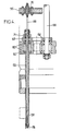
- the apparatus which will be described by way of example is intended to cut the guide tubes and the central instrumentation tube of a fuel assembly of the kind shown in FIG. 1, just below the high grid 12 that is ie at the level indicated by line AA.
- the assembly includes an upper end piece 14 provided with anti-theft springs 15 and connected to the lower end piece (not shown) by guide tubes 16 and a tube central instrumentation 17.
- the end pieces, the tubes 16-17 and the grids distributed along the guide tubes constitute the skeleton of the assembly, which holds the fuel rods 11.
- the assemblies commonly used at present include twenty -five guide tubes 16 which it is desirable to cut to approximately 2 cm below the high grid 12, the only one shown in FIG. 1, so that the upper end part of the rods 11 is well released once the upper end piece has been removed.
- the end separation device shown schematically in Figure 2 can be viewed as comprising a frame, a cutting assembly 20 movable vertically relative to the frame by first motor means, generally constituted by a hydraulic cylinder 22, and a set of expansion 24, movable vertically relative to the cutting assembly by second motor means such as a hydraulic cylinder 26.
- the frame shown in Figure 2 includes a support 28 mounted on vertical slides 30 of a carriage 32 for horizontal movement.
- a cylinder 34 makes it possible to adjust the height of the support 28.
- On the support is fixed a chassis 36 carrying the cylinder of the cylinder 22 and comprising vertical columns 38 for guiding the cutting assembly 20.
- a lower plate of the chassis 36 is provided centering pins 40 intended to engage in corresponding holes in the upper end piece and hooks 42, four in number for example, actuable by jacks 44, to press the chassis plate 36 against the end piece.
- Ejector levers 46 controlled by jacks 48, make it possible to drive the end piece down to separate it from the device, as will be seen below.
- the cutting assembly 20 is suspended from the piston of the jack 22. It comprises a table 50 connected to the plate by columns 51, in which are mounted rotary pins 52 (only one of which is shown in Figure 2) projecting downward, through guide holes in the chassis plate 36. A common electric motor 54 is coupled to the pins by means for driving them simultaneously rotating. The distribution of the pins corresponds to that of the guide tubes and possibly of the instrumentation tube of the assembly whose tip is to be detached.
- the cutting assembly 20 slides, during its up and down movements controlled by the jack 22, on the columns 38.
- the lower part of the pins is expandable so as to be able to assume a retracted position, in which the cutting elements which it carries are out of contact with the wall of the corresponding guide tube (which allows insert the pins into the tubes and remove them) and a deployed position where the cutting elements attack the wall of the guide tubes.
- the expansion assembly 24 which makes it possible to deploy and retract the lower part of all the pins at once, is suspended from the piston of the jack 26.
- This assembly slides on vertical columns belonging to the cutting assembly 20.
- Hanging rods 58 in a number equal to that of the pins hang from a lower plate 56 of the cutting assembly, having the same arrangement as the pins and the end part of which constitutes a push button for forced expansion and folding of the lower part. some pins.
- FIGs 3 and 4 show a possible constitution of the pins 52 and the elements associated with them.
- Each spindle 52 rotates in bearings 60 mounted in the table 50 and carries a pinion 62 coupled, by a gear train 64, to the central shaft 66 connected to the motor shaft 54 by a coupling 68.
- the motor provides thus the cutting power necessary for all pins 52 at a time.
- Some of the spindles receive this power, not directly from the motor, but via another spindle, thanks to additional gears such as that shown at 71 in FIG. 4.
- the pins 58 for expansion of the pins are retained axially in the plate 56 by ball bearings 70 ( Figure 4).
- a diametrical slot 74 in this lower part ( Figure 6) separates two clamp arms which each carry a cutting element consisting of a grain 76
- the internal passage of the spindle has, at the level of the cutting grains 76, a narrowed section.
- each rod 58 has a frustoconical part widening upwards which, in this position, let the fingers of the clamp retract radially to a position where the radial size of the grains 76 is less than the cross section of the guide tube to be cut.
- a conical end piece 78 At the end of the rod 58 is fixed, for example by a threaded connection and a nut, a conical end piece 78 whose internal wall is applied against a terminal cone 80 of the spindle 52.
- this conical tip causes forced radial retraction of the pliers' fingers ( Figure 5).
- the end piece is released from the clamp and the fingers are deployed by the frustoconical part of the rod.
- the apparatus is brought above an assembly to be treated using the carriage 32.
- the frame 36 is lowered onto the assembly using the vertical carriage 28 sliding on the guides 30 linked to the carriage 32, driven by the jack 34, to engage the centering pins 40 in the upper end piece.
- the cylinders 44 are actuated to lock the end piece against the chassis plate 36.
- the ejectors are in the position shown in Figure 2.
- the pistons of the cylinders 22 and 26 are in the high position.
- the jack 22 is then actuated to lower the cutting assembly 20. All the pins 52, the lower clamp of which is retracted, penetrate into the guide tubes to bring the cutting grains 76 to the required level, which advantageously corresponds to the end of low stroke of the cylinder piston.
- the motor 54 is then supplied and simultaneously drives all the pins 52, then the jack 26 is supplied.
- the expansion assembly 24 descends, over a stroke which can for example be 50 mm.
- the tapered ends 78 release the end clamps and the conical parts of the rods 58 gradually push the clamp arms outward, to radially advance the grains 76 and cut the guide tubes.
- the precision of movement which a conical pusher allows to obtain guarantees that the cutting grains 76 do not protrude out of the guide tubes to damage the adjacent rods.
- the rods 58 are raised by control of the jack 26 in the direction of the piston rising.
- the conical pusher of each rod releases the corresponding clamp, the forced retraction of which is caused by the conical end piece 78.
- a chamber 82 for receiving the chips coming from the cut is provided in each conical end piece 78.
- FIGS. 8 and 9 show for example an alternative embodiment in which the lower end part of the pin 52 is separated by slots in three fingers having each an angular development of 120 °, each carrying a toothed sector 84.
- Figure 8 shows the sectors in the retracted position, in contact with each other.
- Figure 9 shows the forced expansion of the sectors by the conical pusher of the rod 58 to cause the cutting of the guide tube.
Landscapes
- Physics & Mathematics (AREA)
- Engineering & Computer Science (AREA)
- Plasma & Fusion (AREA)
- General Engineering & Computer Science (AREA)
- High Energy & Nuclear Physics (AREA)
- Monitoring And Testing Of Nuclear Reactors (AREA)
- Shearing Machines (AREA)
Claims (9)
Applications Claiming Priority (2)
| Application Number | Priority Date | Filing Date | Title |
|---|---|---|---|
| FR8717484 | 1987-12-15 | ||
| FR8717484A FR2624643B1 (fr) | 1987-12-15 | 1987-12-15 | Appareil et procede de separation d'embout d'assemblage combustible nucleaire |
Publications (2)
| Publication Number | Publication Date |
|---|---|
| EP0321334A1 EP0321334A1 (de) | 1989-06-21 |
| EP0321334B1 true EP0321334B1 (de) | 1991-11-06 |
Family
ID=9357882
Family Applications (1)
| Application Number | Title | Priority Date | Filing Date |
|---|---|---|---|
| EP88403165A Expired - Lifetime EP0321334B1 (de) | 1987-12-15 | 1988-12-13 | Apparat und Verfahren zum Abtrennen von Kernbrennstabbündelendstücken |
Country Status (8)
| Country | Link |
|---|---|
| US (1) | US5001949A (de) |
| EP (1) | EP0321334B1 (de) |
| JP (1) | JPH01296197A (de) |
| KR (1) | KR890010925A (de) |
| DE (1) | DE3866088D1 (de) |
| ES (1) | ES2026270T3 (de) |
| FR (1) | FR2624643B1 (de) |
| ZA (1) | ZA889102B (de) |
Families Citing this family (5)
| Publication number | Priority date | Publication date | Assignee | Title |
|---|---|---|---|---|
| FR2624643B1 (fr) * | 1987-12-15 | 1990-05-18 | Framatome Sa | Appareil et procede de separation d'embout d'assemblage combustible nucleaire |
| RU2153713C1 (ru) * | 1998-11-05 | 2000-07-27 | Производственное объединение "МАЯК" | Устройство для отделения концевых деталей отработавших тепловыделяющих сборок |
| US6344739B1 (en) | 1999-02-12 | 2002-02-05 | R/D Tech Inc. | Eddy current probe with multi-use coils and compact configuration |
| FR2901051B1 (fr) * | 2006-05-10 | 2010-05-21 | Nuclear Fuel Ind Ltd | Outil de decoupe de tube chaussette |
| HUE071014T2 (hu) * | 2022-05-03 | 2025-07-28 | Framatome Gmbh | Vágószerkezet és eljárás nukleáris magkomponens vágására |
Family Cites Families (9)
| Publication number | Priority date | Publication date | Assignee | Title |
|---|---|---|---|---|
| US4522780A (en) * | 1982-02-16 | 1985-06-11 | Westinghouse Electric Corp. | Removal and replacement of fuel rods in nuclear fuel assembly |
| IT1176917B (it) * | 1983-10-21 | 1987-08-18 | Westinghouse Electric Corp | Tagliatubi di precisione per interni |
| DE3417742C2 (de) * | 1984-05-12 | 1987-04-09 | Steag Kernenergie Gmbh, 4300 Essen | Verfahren zum Zerlegen von Kernreaktor-Brennelementen und Vorrichtung zur Durchführung des Verfahrens |
| US4667547A (en) * | 1984-09-26 | 1987-05-26 | Westinghouse Electric Corp. | Apparatus and method for removing a top nozzle in reconstituting a fuel assembly |
| US4638543A (en) * | 1985-01-28 | 1987-01-27 | Westinghouse Electric Corp. | Locking tube removal fixture and method in a reconstitutable fuel assembly |
| DE3505242A1 (de) * | 1985-02-15 | 1986-08-21 | Deutsche Gesellschaft für Wiederaufarbeitung von Kernbrennstoffen mbH, 3000 Hannover | Verfahren und vorrichtung zur vereinzelung von brennstaeben eines brennelementes |
| FR2586854B1 (fr) * | 1985-08-29 | 1987-12-04 | Framatome Sa | Procede et dispositif de compactage d'un faisceau de crayons de combustibles |
| IT1205565B (it) * | 1986-11-10 | 1989-03-23 | Sinico Egidio Spa | Dispositivo di tranciatura di un tubo metallico,per espansionae di un utensile a settori in una macchina automatica lavorazioni multiple |
| FR2624643B1 (fr) * | 1987-12-15 | 1990-05-18 | Framatome Sa | Appareil et procede de separation d'embout d'assemblage combustible nucleaire |
-
1987
- 1987-12-15 FR FR8717484A patent/FR2624643B1/fr not_active Expired - Lifetime
-
1988
- 1988-12-05 ZA ZA889102A patent/ZA889102B/xx unknown
- 1988-12-13 ES ES198888403165T patent/ES2026270T3/es not_active Expired - Lifetime
- 1988-12-13 DE DE8888403165T patent/DE3866088D1/de not_active Expired - Lifetime
- 1988-12-13 EP EP88403165A patent/EP0321334B1/de not_active Expired - Lifetime
- 1988-12-14 KR KR1019880016668A patent/KR890010925A/ko not_active Withdrawn
- 1988-12-15 JP JP63315212A patent/JPH01296197A/ja active Pending
- 1988-12-15 US US07/284,519 patent/US5001949A/en not_active Expired - Fee Related
Also Published As
| Publication number | Publication date |
|---|---|
| ES2026270T3 (es) | 1992-04-16 |
| FR2624643A1 (fr) | 1989-06-16 |
| ZA889102B (en) | 1989-08-30 |
| US5001949A (en) | 1991-03-26 |
| JPH01296197A (ja) | 1989-11-29 |
| FR2624643B1 (fr) | 1990-05-18 |
| DE3866088D1 (de) | 1991-12-12 |
| KR890010925A (ko) | 1989-08-11 |
| EP0321334A1 (de) | 1989-06-21 |
Similar Documents
| Publication | Publication Date | Title |
|---|---|---|
| EP0109902B2 (de) | Vorrichtung zur Wiederherstellung von Brennstoffanordnungen | |
| EP0020272B1 (de) | Beweglicher Gerätehalter für die Arbeit an einer Rohrplatte | |
| CA1302514C (fr) | Dispositif de decoupage par etincelage de la paroi d'une piece tubulaire | |
| FR2677287A1 (fr) | Appareil de changement d'outils pour une poinconneuse a tourelle. | |
| EP0321334B1 (de) | Apparat und Verfahren zum Abtrennen von Kernbrennstabbündelendstücken | |
| FR2599541A1 (fr) | Procede et installation de prelevement de troncon de tube dans un assemblage combustible nucleaire | |
| EP1605242A1 (de) | System zur Benutzung einer Vorrichtung zum Entnehmen einer Probe aus dem Grund oder eines körnigen oder pulverförmigen Materials | |
| FR2615028A1 (fr) | Appareil et procede pour le charge ment de barres de combustible dans les grilles d'assemblages combustibles nucleaires | |
| FR2529444A1 (fr) | Machine pour la preparation de brochettes | |
| EP0218494B1 (de) | Verfahren und Vorrichtung zur Kompaktierung eines Brennstabbündels | |
| EP0344051A1 (de) | Kernbrennelementaufnahme- und Zerlegungszelle | |
| EP0244278B1 (de) | Verfahren zum Einsetzen eines Stabbündels eines Kernbrennstoffbündels in einen Behälter und Anlage zur Durchführung dieses Verfahrens | |
| EP0230172B1 (de) | Stabbündelgreifvorrichtung für ein Kernbrennstabbündel | |
| FR2459934A1 (fr) | Procede et appareil pour monter des raccords sur des tuyaux souples | |
| EP0105779A1 (de) | Gerät und Verfahren zum Schweissen von Kernbrennstoffkonstruktionszusammenbauelementen | |
| FR2690554A1 (fr) | Dispositif et procédé de montage de crayons dans un squelette d'assemblage combustible nucléaire. | |
| EP1541276B1 (de) | Vorrichtung zur automatischen Aufnahme / Rückgabe eines Werkzeugs von einem / in einen Werkzeugstapel | |
| FR2642939A1 (fr) | Procede et dispositifs d'embrochement pour machine a brochettes | |
| FR2555927A1 (fr) | Magasin d'outils pour machine-outil automatique a broche rotative porte-outil montee dans une tete d'usinage | |
| EP0398792B1 (de) | Einrichtung zum Positionieren eines Gerätes in eine zylindrische Höhlung mit regelmässig geordneten Perforationen | |
| EP0493259B1 (de) | Verfahren und Vorrichtung zur Reparatur eines Abstandhalters in einem Kernreaktorbrennstabbündel | |
| BE1004316A4 (fr) | Procede et installation de reconstitution d'assemblage combustible nucleaire. | |
| BE1005869A5 (fr) | Equipement d'assemblage d'un jeu de combustible nucleaire. | |
| EP0391778A1 (de) | Vorrichtung zum Zentrieren eines Interventionsgerät in einem Dampferzeugerrohr | |
| EP0346233A1 (de) | Verfahren zum Verdichten des Skeletts einer nuklearen brennbaren Zusammenstellung |
Legal Events
| Date | Code | Title | Description |
|---|---|---|---|
| PUAI | Public reference made under article 153(3) epc to a published international application that has entered the european phase |
Free format text: ORIGINAL CODE: 0009012 |
|
| AK | Designated contracting states |
Kind code of ref document: A1 Designated state(s): BE CH DE ES GB LI SE |
|
| 17P | Request for examination filed |
Effective date: 19890602 |
|
| 17Q | First examination report despatched |
Effective date: 19910411 |
|
| GRAA | (expected) grant |
Free format text: ORIGINAL CODE: 0009210 |
|
| AK | Designated contracting states |
Kind code of ref document: B1 Designated state(s): BE CH DE ES GB LI SE |
|
| GBT | Gb: translation of ep patent filed (gb section 77(6)(a)/1977) | ||
| REF | Corresponds to: |
Ref document number: 3866088 Country of ref document: DE Date of ref document: 19911212 |
|
| REG | Reference to a national code |
Ref country code: ES Ref legal event code: FG2A Ref document number: 2026270 Country of ref document: ES Kind code of ref document: T3 |
|
| PLBE | No opposition filed within time limit |
Free format text: ORIGINAL CODE: 0009261 |
|
| STAA | Information on the status of an ep patent application or granted ep patent |
Free format text: STATUS: NO OPPOSITION FILED WITHIN TIME LIMIT |
|
| 26N | No opposition filed | ||
| EAL | Se: european patent in force in sweden |
Ref document number: 88403165.9 |
|
| PGFP | Annual fee paid to national office [announced via postgrant information from national office to epo] |
Ref country code: ES Payment date: 19961205 Year of fee payment: 9 |
|
| PGFP | Annual fee paid to national office [announced via postgrant information from national office to epo] |
Ref country code: GB Payment date: 19961206 Year of fee payment: 9 |
|
| PGFP | Annual fee paid to national office [announced via postgrant information from national office to epo] |
Ref country code: SE Payment date: 19961218 Year of fee payment: 9 Ref country code: BE Payment date: 19961218 Year of fee payment: 9 |
|
| PGFP | Annual fee paid to national office [announced via postgrant information from national office to epo] |
Ref country code: CH Payment date: 19961223 Year of fee payment: 9 |
|
| PGFP | Annual fee paid to national office [announced via postgrant information from national office to epo] |
Ref country code: DE Payment date: 19970227 Year of fee payment: 9 |
|
| PG25 | Lapsed in a contracting state [announced via postgrant information from national office to epo] |
Ref country code: GB Free format text: LAPSE BECAUSE OF NON-PAYMENT OF DUE FEES Effective date: 19971213 |
|
| PG25 | Lapsed in a contracting state [announced via postgrant information from national office to epo] |
Ref country code: SE Free format text: LAPSE BECAUSE OF NON-PAYMENT OF DUE FEES Effective date: 19971214 |
|
| PG25 | Lapsed in a contracting state [announced via postgrant information from national office to epo] |
Ref country code: ES Free format text: LAPSE BECAUSE OF EXPIRATION OF PROTECTION Effective date: 19971215 |
|
| PG25 | Lapsed in a contracting state [announced via postgrant information from national office to epo] |
Ref country code: LI Free format text: LAPSE BECAUSE OF NON-PAYMENT OF DUE FEES Effective date: 19971231 Ref country code: CH Free format text: LAPSE BECAUSE OF NON-PAYMENT OF DUE FEES Effective date: 19971231 Ref country code: BE Free format text: LAPSE BECAUSE OF NON-PAYMENT OF DUE FEES Effective date: 19971231 |
|
| BERE | Be: lapsed |
Owner name: FRAMATOME Effective date: 19971231 |
|
| GBPC | Gb: european patent ceased through non-payment of renewal fee |
Effective date: 19971213 |
|
| REG | Reference to a national code |
Ref country code: CH Ref legal event code: PL |
|
| PG25 | Lapsed in a contracting state [announced via postgrant information from national office to epo] |
Ref country code: DE Free format text: LAPSE BECAUSE OF NON-PAYMENT OF DUE FEES Effective date: 19980901 |
|
| EUG | Se: european patent has lapsed |
Ref document number: 88403165.9 |
|
| REG | Reference to a national code |
Ref country code: ES Ref legal event code: FD2A Effective date: 20010201 |