EP0321334B1 - Apparatus and method for separating nuclear fuel assembly nozzles - Google Patents
Apparatus and method for separating nuclear fuel assembly nozzles Download PDFInfo
- Publication number
- EP0321334B1 EP0321334B1 EP88403165A EP88403165A EP0321334B1 EP 0321334 B1 EP0321334 B1 EP 0321334B1 EP 88403165 A EP88403165 A EP 88403165A EP 88403165 A EP88403165 A EP 88403165A EP 0321334 B1 EP0321334 B1 EP 0321334B1
- Authority
- EP
- European Patent Office
- Prior art keywords
- end piece
- cutting
- spindles
- assembly
- fingers
- Prior art date
- Legal status (The legal status is an assumption and is not a legal conclusion. Google has not performed a legal analysis and makes no representation as to the accuracy of the status listed.)
- Expired - Lifetime
Links
Images


Classifications
-
- G—PHYSICS
- G21—NUCLEAR PHYSICS; NUCLEAR ENGINEERING
- G21C—NUCLEAR REACTORS
- G21C3/00—Reactor fuel elements and their assemblies; Selection of substances for use as reactor fuel elements
- G21C3/02—Fuel elements
- G21C3/04—Constructional details
-
- G—PHYSICS
- G21—NUCLEAR PHYSICS; NUCLEAR ENGINEERING
- G21C—NUCLEAR REACTORS
- G21C19/00—Arrangements for treating, for handling, or for facilitating the handling of, fuel or other materials which are used within the reactor, e.g. within its pressure vessel
- G21C19/34—Apparatus or processes for dismantling nuclear fuel, e.g. before reprocessing ; Apparatus or processes for dismantling strings of spent fuel elements
-
- Y—GENERAL TAGGING OF NEW TECHNOLOGICAL DEVELOPMENTS; GENERAL TAGGING OF CROSS-SECTIONAL TECHNOLOGIES SPANNING OVER SEVERAL SECTIONS OF THE IPC; TECHNICAL SUBJECTS COVERED BY FORMER USPC CROSS-REFERENCE ART COLLECTIONS [XRACs] AND DIGESTS
- Y02—TECHNOLOGIES OR APPLICATIONS FOR MITIGATION OR ADAPTATION AGAINST CLIMATE CHANGE
- Y02E—REDUCTION OF GREENHOUSE GAS [GHG] EMISSIONS, RELATED TO ENERGY GENERATION, TRANSMISSION OR DISTRIBUTION
- Y02E30/00—Energy generation of nuclear origin
- Y02E30/30—Nuclear fission reactors
-
- Y—GENERAL TAGGING OF NEW TECHNOLOGICAL DEVELOPMENTS; GENERAL TAGGING OF CROSS-SECTIONAL TECHNOLOGIES SPANNING OVER SEVERAL SECTIONS OF THE IPC; TECHNICAL SUBJECTS COVERED BY FORMER USPC CROSS-REFERENCE ART COLLECTIONS [XRACs] AND DIGESTS
- Y10—TECHNICAL SUBJECTS COVERED BY FORMER USPC
- Y10T—TECHNICAL SUBJECTS COVERED BY FORMER US CLASSIFICATION
- Y10T82/00—Turning
- Y10T82/16—Severing or cut-off
- Y10T82/16426—Infeed means
- Y10T82/16655—Infeed means with means to rotate tool[s]
- Y10T82/16672—Infeed means with means to rotate tool[s] including rotatable cutters supporting work
Definitions
- the subject of the invention is an apparatus and a method for separating a nozzle, generally of an upper nozzle, for nuclear fuel assembly, this nozzle having an adapter plate pierced with passages for receiving guide tubes fixed to the adapter plate. and another tip to form a skeleton.
- the fuel assemblies exhausted after one or more reactor cycles, are extracted from the reactor vessel and placed in storage racks placed at the bottom of a deactivation pool.
- EP-A-145185 and EP-A-175974 are already known devices for successively or simultaneously cutting the guide tubes. Most of these devices are built to cut the guide tubes from the inside, so that the operation is not hampered by the pencil bundle of assembly. Since any damage to a pencil would cause contamination, these devices are designed so as not to damage the sheath of the pencil adjacent to the tube to be cut. This condition is easily fulfilled when the guide tubes are cut immediately below the end piece. It is no longer the same when you want to cut the tube below the end of the pencils, so as to facilitate the subsequent gripping of the latter using a gripper.
- the invention aims in particular to provide an assembly end separation device that better meets those previously known to the requirements of practice, in particular in that it makes it possible to simultaneously cut all of the guide tubes (and possibly the tube instrumentation) of the assembly in a precise manner, with a small volume of debris and allowing the removal of the detached endpiece, without the intervention of an additional tool.
- Each of the rods advantageously comprises a terminal tip which causes the forced radial retraction of the fingers when the rods are brought into a high position relative to the spindle and a forced deployment cone of the fingers when the rod is lowered relative to the spindle from said high position.
- the frame advantageously comprises, in addition to the means for fixing to the end piece, ejector levers intended to bear on the detached end piece and to drive it from the centering means downwards.
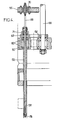
- the apparatus which will be described by way of example is intended to cut the guide tubes and the central instrumentation tube of a fuel assembly of the kind shown in FIG. 1, just below the high grid 12 that is ie at the level indicated by line AA.
- the assembly includes an upper end piece 14 provided with anti-theft springs 15 and connected to the lower end piece (not shown) by guide tubes 16 and a tube central instrumentation 17.
- the end pieces, the tubes 16-17 and the grids distributed along the guide tubes constitute the skeleton of the assembly, which holds the fuel rods 11.
- the assemblies commonly used at present include twenty -five guide tubes 16 which it is desirable to cut to approximately 2 cm below the high grid 12, the only one shown in FIG. 1, so that the upper end part of the rods 11 is well released once the upper end piece has been removed.
- the end separation device shown schematically in Figure 2 can be viewed as comprising a frame, a cutting assembly 20 movable vertically relative to the frame by first motor means, generally constituted by a hydraulic cylinder 22, and a set of expansion 24, movable vertically relative to the cutting assembly by second motor means such as a hydraulic cylinder 26.
- the frame shown in Figure 2 includes a support 28 mounted on vertical slides 30 of a carriage 32 for horizontal movement.
- a cylinder 34 makes it possible to adjust the height of the support 28.
- On the support is fixed a chassis 36 carrying the cylinder of the cylinder 22 and comprising vertical columns 38 for guiding the cutting assembly 20.
- a lower plate of the chassis 36 is provided centering pins 40 intended to engage in corresponding holes in the upper end piece and hooks 42, four in number for example, actuable by jacks 44, to press the chassis plate 36 against the end piece.
- Ejector levers 46 controlled by jacks 48, make it possible to drive the end piece down to separate it from the device, as will be seen below.
- the cutting assembly 20 is suspended from the piston of the jack 22. It comprises a table 50 connected to the plate by columns 51, in which are mounted rotary pins 52 (only one of which is shown in Figure 2) projecting downward, through guide holes in the chassis plate 36. A common electric motor 54 is coupled to the pins by means for driving them simultaneously rotating. The distribution of the pins corresponds to that of the guide tubes and possibly of the instrumentation tube of the assembly whose tip is to be detached.
- the cutting assembly 20 slides, during its up and down movements controlled by the jack 22, on the columns 38.
- the lower part of the pins is expandable so as to be able to assume a retracted position, in which the cutting elements which it carries are out of contact with the wall of the corresponding guide tube (which allows insert the pins into the tubes and remove them) and a deployed position where the cutting elements attack the wall of the guide tubes.
- the expansion assembly 24 which makes it possible to deploy and retract the lower part of all the pins at once, is suspended from the piston of the jack 26.
- This assembly slides on vertical columns belonging to the cutting assembly 20.
- Hanging rods 58 in a number equal to that of the pins hang from a lower plate 56 of the cutting assembly, having the same arrangement as the pins and the end part of which constitutes a push button for forced expansion and folding of the lower part. some pins.
- FIGs 3 and 4 show a possible constitution of the pins 52 and the elements associated with them.
- Each spindle 52 rotates in bearings 60 mounted in the table 50 and carries a pinion 62 coupled, by a gear train 64, to the central shaft 66 connected to the motor shaft 54 by a coupling 68.
- the motor provides thus the cutting power necessary for all pins 52 at a time.
- Some of the spindles receive this power, not directly from the motor, but via another spindle, thanks to additional gears such as that shown at 71 in FIG. 4.
- the pins 58 for expansion of the pins are retained axially in the plate 56 by ball bearings 70 ( Figure 4).
- a diametrical slot 74 in this lower part ( Figure 6) separates two clamp arms which each carry a cutting element consisting of a grain 76
- the internal passage of the spindle has, at the level of the cutting grains 76, a narrowed section.
- each rod 58 has a frustoconical part widening upwards which, in this position, let the fingers of the clamp retract radially to a position where the radial size of the grains 76 is less than the cross section of the guide tube to be cut.
- a conical end piece 78 At the end of the rod 58 is fixed, for example by a threaded connection and a nut, a conical end piece 78 whose internal wall is applied against a terminal cone 80 of the spindle 52.
- this conical tip causes forced radial retraction of the pliers' fingers ( Figure 5).
- the end piece is released from the clamp and the fingers are deployed by the frustoconical part of the rod.
- the apparatus is brought above an assembly to be treated using the carriage 32.
- the frame 36 is lowered onto the assembly using the vertical carriage 28 sliding on the guides 30 linked to the carriage 32, driven by the jack 34, to engage the centering pins 40 in the upper end piece.
- the cylinders 44 are actuated to lock the end piece against the chassis plate 36.
- the ejectors are in the position shown in Figure 2.
- the pistons of the cylinders 22 and 26 are in the high position.
- the jack 22 is then actuated to lower the cutting assembly 20. All the pins 52, the lower clamp of which is retracted, penetrate into the guide tubes to bring the cutting grains 76 to the required level, which advantageously corresponds to the end of low stroke of the cylinder piston.
- the motor 54 is then supplied and simultaneously drives all the pins 52, then the jack 26 is supplied.
- the expansion assembly 24 descends, over a stroke which can for example be 50 mm.
- the tapered ends 78 release the end clamps and the conical parts of the rods 58 gradually push the clamp arms outward, to radially advance the grains 76 and cut the guide tubes.
- the precision of movement which a conical pusher allows to obtain guarantees that the cutting grains 76 do not protrude out of the guide tubes to damage the adjacent rods.
- the rods 58 are raised by control of the jack 26 in the direction of the piston rising.
- the conical pusher of each rod releases the corresponding clamp, the forced retraction of which is caused by the conical end piece 78.
- a chamber 82 for receiving the chips coming from the cut is provided in each conical end piece 78.
- FIGS. 8 and 9 show for example an alternative embodiment in which the lower end part of the pin 52 is separated by slots in three fingers having each an angular development of 120 °, each carrying a toothed sector 84.
- Figure 8 shows the sectors in the retracted position, in contact with each other.
- Figure 9 shows the forced expansion of the sectors by the conical pusher of the rod 58 to cause the cutting of the guide tube.
Description
L'invention a pour objet un appareil et un procédé de séparation d'un embout, généralement d'un embout supérieur, d'assemblage combustible nucléaire, cet embout ayant une plaque adaptatrice percée de passages de réception de tubes guides fixés à la plaque adaptatrice et à un autre embout pour constituer un squelette.The subject of the invention is an apparatus and a method for separating a nozzle, generally of an upper nozzle, for nuclear fuel assembly, this nozzle having an adapter plate pierced with passages for receiving guide tubes fixed to the adapter plate. and another tip to form a skeleton.
Les assemblages combustibles actuels pour réacteur nucléaire à eau sous pression comportent un tel squelette, complété par des grilles destinées à maintenir des crayons contenant des pastilles de combustible nucléaire parallèlement les uns aux autres et aux noeuds d'un réseau régulier, généralement carré. Dans la plupart des assemblages, les crayons n'occupent pas toute la longueur de l'espace limité par les embouts et, en particulier, n'ont qu'une faible saillie au-dessus de la grille supérieure.Current fuel assemblies for a pressurized water nuclear reactor include such a skeleton, completed by grids intended to hold rods containing nuclear fuel pellets parallel to each other and to the nodes of a regular network, generally square. In most assemblies, the pencils do not occupy the entire length of the space limited by the end pieces and, in particular, have only a slight projection above the upper grid.
Les assemblages combustibles, épuisés après un ou plusieurs cycles en réacteur, sont extraits de la cuve du réacteur et mis dans des râteliers de stockage placés au fond d'une piscine de désactivation. Pour réduire le volume nécessaire au stockage de longue durée des crayons de combustible, on a déjà proposé de démanteler les assemblages, d'en extraire les crayons et de rassembler ces derniers en bottes de crayons jointifs. Le démantèlement d'un assemblage implique d'enlever un embout, donc de découper les tubes guides (et éventuellement le tube central d'appareillage) qui le relient à l'autre embout.The fuel assemblies, exhausted after one or more reactor cycles, are extracted from the reactor vessel and placed in storage racks placed at the bottom of a deactivation pool. To reduce the volume required for long-term storage of the fuel rods, it has already been proposed to dismantle the assemblies, to extract the rods and to assemble them in bundles of contiguous rods. Dismantling an assembly involves removing a tip, therefore cutting the guide tubes (and possibly the central fitting tube) which connect it to the other tip.
On connaît déjà EP-A-145185 et EP-A-175974 des appareils permettant de découper successivement ou simultanément les tubes guides. La plupart de ces appareils sont construits pour couper les tubes guides par l'intérieur, pour que l'opération ne soit pas gênée par le faisceau de crayons de l'assemblage. Etant donné que tout endommagement d'un crayon provoquerait une contamination, ces appareils sont conçus de façon à ne pas entamer la gaine des crayons adjacents au tube à couper. Cette condition est facile à remplir lorsqu'on coupe les tubes guides immédiatement au-dessous de l'embout. Il n'en est plus de même lorsque l'on veut trancher le tube au-dessous de l'extrémité des crayons, de façon à faciliter la prise ultérieure de ces derniers à l'aide d'une pince de préhension.EP-A-145185 and EP-A-175974 are already known devices for successively or simultaneously cutting the guide tubes. Most of these devices are built to cut the guide tubes from the inside, so that the operation is not hampered by the pencil bundle of assembly. Since any damage to a pencil would cause contamination, these devices are designed so as not to damage the sheath of the pencil adjacent to the tube to be cut. This condition is easily fulfilled when the guide tubes are cut immediately below the end piece. It is no longer the same when you want to cut the tube below the end of the pencils, so as to facilitate the subsequent gripping of the latter using a gripper.
L'invention vise notamment à fournir un appareil de séparation d'embout d'assemblage répondant mieux que ceux antérieurement connus aux exigences de la pratique, notamment en ce qu'il permet de sectionner simultanément l'ensemble des tubes guides (et éventuellement le tube d'instrumentation) de l'assemblage de façon précise, avec un faible volume de débris et en permettant l'enlèvement de l'embout détaché, sans intervention d'un outil supplémentaire.The invention aims in particular to provide an assembly end separation device that better meets those previously known to the requirements of practice, in particular in that it makes it possible to simultaneously cut all of the guide tubes (and possibly the tube instrumentation) of the assembly in a precise manner, with a small volume of debris and allowing the removal of the detached endpiece, without the intervention of an additional tool.
Dans ce but, l'invention propose un appareil de séparation d'embout d'assemblage combustible nucléaire, l'embout à séparer ayant une plaque adaptatrice percée de passages de réception de tubes guides fixés à la plaque et à un autre embout, l'appareil comprenant plusieurs outils de coupe insérables dans les tubes guides et un bâti muni, d'une part, de moyens de fixation amovible et de centrage sur l'embout à séparer et, d'autre part, de moyens de guidage et de maintien des outils dans une répartition fixe et déterminée, correspondant à celle des tubes guides,
- caractérisé en ce que lesdits outils comportent chacun une broche creuse dont la partie terminale est fractionnée par des fentes longitudinales en doigts expansibles portant un taillant de coupe et une tige déplaçable axialement le long de la broche et coopérant avec elle pour déployer radialement les doigts et les rétracter,
- en ce que les broches sont montées rotatives sur un plateau déplaçable verticalement par rapport au bâti par des premiers moyens moteurs et portant un moteur d'entraînement simultané en rotation de l'ensemble des broches,
- et en ce que les tiges sont portées par un ensemble d'expansion déplaçable verticalement par rapport au plateau par des seconds moyens moteurs.
- characterized in that said tools each comprise a hollow spindle the end part of which is divided by longitudinal slots in expandable fingers carrying a cutting cutter and a rod movable axially along the spindle and cooperating with it to deploy the fingers and the retract,
- in that the pins are rotatably mounted on a plate movable vertically with respect to the frame by first motor means and carrying a motor for simultaneously driving all the pins in rotation,
- and in that the rods are carried by an expansion assembly movable vertically relative to the plate by second motor means.
Chacune des tiges comporte avantageusement un embout terminal qui provoque la rétraction radiale forcée des doigts lorsque les tiges sont amenées dans une position haute par rapport à la broche et un cône de déploiement forcé des doigts lors de l'abaissement de la tige par rapport à la broche à partir de ladite position haute. Le bâti comporte avantageusement, en plus des moyens de fixation sur l'embout, des leviers éjecteurs destinés à prendre appui sur l'embout détaché et à le chasser des moyens de centrage vers le bas.Each of the rods advantageously comprises a terminal tip which causes the forced radial retraction of the fingers when the rods are brought into a high position relative to the spindle and a forced deployment cone of the fingers when the rod is lowered relative to the spindle from said high position. The frame advantageously comprises, in addition to the means for fixing to the end piece, ejector levers intended to bear on the detached end piece and to drive it from the centering means downwards.
L'invention propose également un procédé de séparation d'embout d'un assemblage du genre ci-dessus défini, caractérisé en ce que:
- ― on fixe temporairement un châssis sur l'embout à séparer, en alignement avec ce dernier,
- ― on déplace simultanément, par rapport au châssis, les broches d'un jeu de broches dans un sens provoquant l'insertion des broches dans les tubes guides sur une profondeur telle qu'une partie terminale des broches, expansible et munie d'éléments de coupe, soit face à l'emplacement de séparation,
- ― on entraîne en rotation simultanément l'ensemble des tiges,
- ― et on provoque l'extension progressive des parties terminales par insertion simultanée, dans l'ensemble des broches, de tiges.
- - a chassis is temporarily fixed on the nozzle to be separated, in alignment with the latter,
- - The pins of a set of pins are moved simultaneously with respect to the chassis in a direction causing the insertion of the pins in the guide tubes to a depth such that an end portion of the pins, expandable and provided with elements of section, either facing the separation location,
- - all the rods are rotated simultaneously,
- - And provokes the progressive extension of the terminal parts by simultaneous insertion, in all the pins, of rods.
L'invention sera mieux comprise à la lecture de la description qui suit d'un mode particulier de réalisation de l'invention et de variantes, donnés à titre d'exemples non limitatifs. L'invention se réfère aux dessins qui l'accompagnent, dans lesquels:
- ― la Figure 1 montre schématiquement, en élévation et en coupe partielle, la partie haute d'un assemblage combustible nucléaire;
- ― la Figure 2 est un schéma montrant la constitution générale d'un appareil suivant l'invention, en élévation;
- ― la Figure 3 est une vue, en élévation et en coupe partielle, du montage d'un des outils de coupe de l'appareil de la Figure 2;
- ― la Figure 4 est une vue de détail montrant, à grande échelle, l'outil de coupe de la Figure 3 et sa liaison avec le moteur d'entraînement en rotation;
- ― la Figure 5 est une vue de détail à grande échelle, montrant la partie terminale de l'outil de coupe de la Figure 4;
- ― la Figure 6 est une coupe suivant la ligne VI-VI de la Figure 5;
- ― la Figure 7, similaire à la Figure 5, montre une variante de réalisation;
- ― les Figures 8 et 9, similaires à la Figure 6, montrent une variante de réalisation de la broche de l'appareil, respectivement en position rétractée et déployée.
- - Figure 1 shows schematically, in elevation and in partial section, the upper part of a nuclear fuel assembly;
- - Figure 2 is a diagram showing the general constitution of an apparatus according to the invention, in elevation;
- - Figure 3 is a view, in elevation and in partial section, of the mounting of one of the cutting tools of the apparatus of Figure 2;
- - Figure 4 is a detail view showing, on a large scale, the cutting tool of Figure 3 and its connection with the rotary drive motor;
- - Figure 5 is a detail view on a large scale, showing the end part of the cutting tool of Figure 4;
- - Figure 6 is a section along line VI-VI of Figure 5;
- - Figure 7, similar to Figure 5, shows an alternative embodiment;
- - Figures 8 and 9, similar to Figure 6, show an alternative embodiment of the pin of the device, respectively in the retracted and deployed position.
L'appareil qui sera décrit à titre d'exemple est destiné à couper les tubes guides et le tube central d'instrumentation d'un assemblage combustible du genre montré en Figure 1, juste au-dessous de la grille haute 12 c'est-à-dire au niveau indiqué par la ligne AA. L'assemblage comporte un embout supérieur 14 muni de ressorts anti-envol 15 et relié à l'embout inférieur (non représenté) par des tubes guides 16 et un tube central d'instrumentation 17. Les embouts, les tubes 16-17 et des grilles réparties le long des tubes guides constituent le squelette de l'assemblage, qui maintient les crayons de combustible 11. Les assemblages couramment utilisés à l'heure actuelle comportent vingt-cinq tubes guides 16 qu'il est souhaitable de couper à 2 cm environ sous la grille haute 12, seule représentée sur la Figure 1, pour que la partie terminale haute des crayons 11 soit bien dégagée une fois l'embout supérieur enlevé.The apparatus which will be described by way of example is intended to cut the guide tubes and the central instrumentation tube of a fuel assembly of the kind shown in FIG. 1, just below the
L'appareil de séparation d'embout montré schématiquement en Figure 2 peut être regardé comme comprenant un bâti, un ensemble de coupe 20 déplaçable verticalement par rapport au bâti par des premiers moyens moteurs, généralement constitués par un vérin hydraulique 22, et un ensemble d'expansion 24, déplaçable verticalement par rapport à l'ensemble de coupe par des seconds moyens moteurs tels qu'un vérin hydraulique 26.The end separation device shown schematically in Figure 2 can be viewed as comprising a frame, a
Le bâti montré sur la Figure 2 comporte un support 28 monté sur des glissières verticales 30 d'un chariot 32 de déplacement horizontal. Un vérin 34 permet de régler la hauteur du support 28. Sur le support est fixé un châssis 36 portant le cylindre du vérin 22 et comportant des colonnes verticales 38 de guidage de l'ensemble de coupe 20. Un plateau inférieur du châssis 36 est muni de pions de centrage 40 destinés à s'engager dans des trous correspondants de l'embout supérieur et de crochets 42, au nombre de quatre par exemple, actionnables par des vérins 44, pour plaquer le plateau du châssis 36 contre l'embout. Des leviers éjecteurs 46, commandés par des vérins 48, permettent de chasser l'embout vers le bas pour le séparer de l'appareil, comme on le verra plus loin.The frame shown in Figure 2 includes a
L'ensemble de coupe 20 est suspendu au piston du vérin 22. Il comporte une table 50 reliée au plateau par des colonnes 51, dans laquelle sont montées des broches rotatives 52 (dont une seule est montrée sur la Figure 2) faisant saillie vers le bas, à travers des trous de guidage ménagés dans le plateau du châssis 36. Un moteur électrique commun 54 est couplé aux broches par des moyens permettant de les entraîner simultanément en rotation. La répartition des broches correspond à celle des tubes guides et éventuellement du tube d'instrumentation de l'assemblage dont l'embout est à détacher. L'ensemble de coupe 20 coulisse, lors de ses mouvements de montée et de descente commandés par le vérin 22, sur les colonnes 38.The
Comme on le verra plus loin, la partie inférieure des broches est expansible de façon à pouvoir prendre une position rétractée, dans laquelle des éléments de coupe qu'elle porte sont hors de contact avec la paroi du tube guide correspondant (ce qui permet d'insérer les broches dans les tubes et de les en retirer) et une position déployée où les éléments de coupe attaquent la paroi des tubes guides.As will be seen below, the lower part of the pins is expandable so as to be able to assume a retracted position, in which the cutting elements which it carries are out of contact with the wall of the corresponding guide tube (which allows insert the pins into the tubes and remove them) and a deployed position where the cutting elements attack the wall of the guide tubes.
L'ensemble d'expansion 24, qui permet de déployer et de rétracter la partie inférieure de toutes les broches à la fois, est suspendu au piston du vérin 26. Cet ensemble coulisse sur des colonnes verticales appartenant à l'ensemble de coupe 20. A une plaque inférieure 56 de l'ensemble de coupe sont suspendues des tiges 58 en nombre égal à celui des broches, présentant la même disposition que les broches et dont la partie terminale constitue un poussoir d'expansion et de repliement forcé de la partie inférieure des broches.The
Les Figures 3 et 4 montrent une constitution possible des broches 52 et des éléments qui leur sont associés. Chaque broche 52 tourne dans des roulements 60 montés dans la table 50 et porte un pignon 62 couplé, par un train d'engrenages 64, à l'arbre central 66 relié à l'arbre du moteur 54 par un accouplement 68. Le moteur fournit ainsi la puissance de coupe nécessaire à toutes les broches 52 à la fois. Certaines des broches reçoivent cette puissance, non pas directement du moteur, mais par l'intermédiaire d'une autre broche, grâce à des engrenages supplémentaires tels que celui montré en 71 sur la Figure 4. Les tiges 58 d'expansion des broches sont retenues axialement dans la plaque 56 par des roulements à billes 70 (Figure 4).Figures 3 and 4 show a possible constitution of the
Les parties inférieures de toutes les broches sont identiques et peuvent avoir la constitution montrée en Figures 5 à 7. Une fente diamétrale 74 dans cette partie inférieure (Figure 6) sépare deux bras de pince qui portent chacun un élément de coupe constitué par un grain 76. Le passage intérieur de la broche présente, au droit des grains de coupe 76, une section rétrécie.The lower parts of all the pins are identical and can have the constitution shown in Figures 5 to 7. A
Lorsque le piston du vérin 26 est en position haute, les tiges 58 occupent la position représentée en Figure 5. Chaque tige 58 présente une partie tronconique s'évasant vers le haut qui, dans cette position, laissent les doigts de la pince se rétracter radialement jusqu'à une position où l'encombrement radial des grains 76 est inférieur à la section droite du tube guide à découper. A l'extrémité de la tige 58 est fixé, par exemple par une liaison filetée et un écrou, un embout conique 78 dont la paroi interne vient s'appliquer contre un cône terminal 80 de la broche 52. Lorsque le piston du vérin 26 est en position haute, cet embout conique provoque la rétraction radiale forcée des doigts de la pince (Figure 5). Inversement, lorsque le piston du vérin est en position basse, l'embout est dégagé de la pince et les doigts sont déployés par la partie tronconique de la tige.When the piston of the
Le fonctionnement du dispositif qui vient d'être décrit est le suivant.The operation of the device which has just been described is as follows.
L'appareil est amené au-dessus d'un assemblage à traiter à l'aide du chariot 32. Le châssis 36 est descendu sur l'assemblage à l'aide du chariot vertical 28 glissant sur les guides 30 liés au chariot 32, entraîné par le vérin 34, pour engager les pions de centrage 40 dans l'embout supérieur. Les vérins 44 sont actionnés pour verrouiller l'embout contre le plateau du châssis 36. Les éjecteurs sont dans la position montrée en Figure 2. Les pistons des vérins 22 et 26 sont en position haute.The apparatus is brought above an assembly to be treated using the
Le vérin 22 est alors actionné pour descendre l'ensemble de coupe 20. Toutes les broches 52, dont la pince inférieure est rétractée, pénètrent dans les tubes guides pour amener les grains de coupe 76 au niveau requis, qui correspond avantageusement à la fin de course basse du piston de vérin.The
Le moteur 54 est alors alimenté et entraîne simultanément toutes les broches 52, puis le vérin 26 est alimenté. L'ensemble d'expansion 24 descend, sur une course qui peut par exemple être de 50 mm. Les embouts coniques 78 libèrent les pinces terminales et les parties coniques des tiges 58 refoulent progressivement les bras de pince vers l'extérieur, pour avancer radialement les grains 76 et couper les tubes guides. La précision de déplacement que permet d'obtenir un poussoir conique garantit que les grains de coupe 76 ne prenent pas une saillie hors des tubes guides pour endommager les crayons adjacents.The
Une fois la coupe effectuée, les tiges 58 sont remontées par commande du vérin 26 dans le sens de la remontée du piston. Le poussoir conique de chaque tige libère la pince correspondante, dont la rétraction forcée est provoquée par l'embout conique 78.Once the cut has been made, the
Dans la variante de réalisation montrée en Figure 7, où les éléments correspondant à ceux de la Figure 5 sont désignés par le même numéro de référence, une chambre 82 de réception des copeaux provenant de la découpe est ménagée dans chaque embout conique 78.In the variant embodiment shown in FIG. 7, where the elements corresponding to those of FIG. 5 are designated by the same reference number, a
Les éléments de coupe ne sont pas nécessairement des grains du genre montré en Figures 5 et 6. Les Figures 8 et 9 montrent par exemple une variante de réalisation dans laquelle la partie terminale inférieure de la broche 52 est séparée par des fentes en trois doigts ayant chacun un développement angulaire de 120°, portant chacun un secteur denté 84. La Figure 8 montre les secteurs en position rétractée, en contact les uns avec les autres. La Figure 9 montre l'expansion forcée des secteurs par le poussoir conique de la tige 58 pour provoquer la découpe du tube guide.The cutting elements are not necessarily grains of the kind shown in Figures 5 and 6. Figures 8 and 9 show for example an alternative embodiment in which the lower end part of the
Claims (9)
Applications Claiming Priority (2)
| Application Number | Priority Date | Filing Date | Title |
|---|---|---|---|
| FR8717484 | 1987-12-15 | ||
| FR8717484A FR2624643B1 (en) | 1987-12-15 | 1987-12-15 | APPARATUS AND METHOD FOR SEPARATING A NUCLEAR FUEL ASSEMBLY NOZZLE |
Publications (2)
| Publication Number | Publication Date |
|---|---|
| EP0321334A1 EP0321334A1 (en) | 1989-06-21 |
| EP0321334B1 true EP0321334B1 (en) | 1991-11-06 |
Family
ID=9357882
Family Applications (1)
| Application Number | Title | Priority Date | Filing Date |
|---|---|---|---|
| EP88403165A Expired - Lifetime EP0321334B1 (en) | 1987-12-15 | 1988-12-13 | Apparatus and method for separating nuclear fuel assembly nozzles |
Country Status (8)
| Country | Link |
|---|---|
| US (1) | US5001949A (en) |
| EP (1) | EP0321334B1 (en) |
| JP (1) | JPH01296197A (en) |
| KR (1) | KR890010925A (en) |
| DE (1) | DE3866088D1 (en) |
| ES (1) | ES2026270T3 (en) |
| FR (1) | FR2624643B1 (en) |
| ZA (1) | ZA889102B (en) |
Families Citing this family (4)
| Publication number | Priority date | Publication date | Assignee | Title |
|---|---|---|---|---|
| FR2624643B1 (en) * | 1987-12-15 | 1990-05-18 | Framatome Sa | APPARATUS AND METHOD FOR SEPARATING A NUCLEAR FUEL ASSEMBLY NOZZLE |
| US6344739B1 (en) | 1999-02-12 | 2002-02-05 | R/D Tech Inc. | Eddy current probe with multi-use coils and compact configuration |
| FR2901051B1 (en) * | 2006-05-10 | 2010-05-21 | Nuclear Fuel Ind Ltd | TOOL FOR CUTTING TUBE SOCK |
| EP4273888A1 (en) * | 2022-05-03 | 2023-11-08 | Framatome GmbH | Cutting device and method for cutting a nuclear core component |
Family Cites Families (9)
| Publication number | Priority date | Publication date | Assignee | Title |
|---|---|---|---|---|
| US4522780A (en) * | 1982-02-16 | 1985-06-11 | Westinghouse Electric Corp. | Removal and replacement of fuel rods in nuclear fuel assembly |
| IT1176917B (en) * | 1983-10-21 | 1987-08-18 | Westinghouse Electric Corp | PRECISION INTERIOR CUTTERS |
| DE3417742A1 (en) * | 1984-05-12 | 1985-11-14 | Steag Kernenergie Gmbh, 4300 Essen | METHOD FOR DEASSEMBLING FUEL ELEMENTS AND DEVICE FOR CARRYING OUT THE METHOD |
| US4667547A (en) * | 1984-09-26 | 1987-05-26 | Westinghouse Electric Corp. | Apparatus and method for removing a top nozzle in reconstituting a fuel assembly |
| US4638543A (en) * | 1985-01-28 | 1987-01-27 | Westinghouse Electric Corp. | Locking tube removal fixture and method in a reconstitutable fuel assembly |
| DE3505242A1 (en) * | 1985-02-15 | 1986-08-21 | Deutsche Gesellschaft für Wiederaufarbeitung von Kernbrennstoffen mbH, 3000 Hannover | METHOD AND DEVICE FOR SEPARATING FUEL RODS OF A FUEL ELEMENT |
| FR2586854B1 (en) * | 1985-08-29 | 1987-12-04 | Framatome Sa | METHOD AND DEVICE FOR COMPACTING A BEAM OF FUEL PENCILS |
| IT1205565B (en) * | 1986-11-10 | 1989-03-23 | Sinico Egidio Spa | METAL TUBE SHEARING DEVICE, FOR EXPANSION OF A SECTOR TOOL IN AN AUTOMATIC MULTIPLE PROCESSING MACHINE |
| FR2624643B1 (en) * | 1987-12-15 | 1990-05-18 | Framatome Sa | APPARATUS AND METHOD FOR SEPARATING A NUCLEAR FUEL ASSEMBLY NOZZLE |
-
1987
- 1987-12-15 FR FR8717484A patent/FR2624643B1/en not_active Expired - Lifetime
-
1988
- 1988-12-05 ZA ZA889102A patent/ZA889102B/en unknown
- 1988-12-13 DE DE8888403165T patent/DE3866088D1/en not_active Expired - Lifetime
- 1988-12-13 EP EP88403165A patent/EP0321334B1/en not_active Expired - Lifetime
- 1988-12-13 ES ES198888403165T patent/ES2026270T3/en not_active Expired - Lifetime
- 1988-12-14 KR KR1019880016668A patent/KR890010925A/en not_active Application Discontinuation
- 1988-12-15 JP JP63315212A patent/JPH01296197A/en active Pending
- 1988-12-15 US US07/284,519 patent/US5001949A/en not_active Expired - Fee Related
Also Published As
| Publication number | Publication date |
|---|---|
| FR2624643B1 (en) | 1990-05-18 |
| ZA889102B (en) | 1989-08-30 |
| DE3866088D1 (en) | 1991-12-12 |
| US5001949A (en) | 1991-03-26 |
| EP0321334A1 (en) | 1989-06-21 |
| FR2624643A1 (en) | 1989-06-16 |
| KR890010925A (en) | 1989-08-11 |
| ES2026270T3 (en) | 1992-04-16 |
| JPH01296197A (en) | 1989-11-29 |
Similar Documents
| Publication | Publication Date | Title |
|---|---|---|
| EP0020272B1 (en) | Mobile tool holder for working a tube sheet | |
| EP0109902B1 (en) | Set-up for repairing a nuclear fuel assembly | |
| EP1605242B1 (en) | System for the use of an apparatus for taking samples in the ground or a granular or pulverulent material | |
| FR2677287A1 (en) | Tool-change apparatus for a turret punch press | |
| EP0321334B1 (en) | Apparatus and method for separating nuclear fuel assembly nozzles | |
| FR2599541A1 (en) | METHOD AND INSTALLATION FOR TAKING THE TUBE SECTION FROM A NUCLEAR FUEL ASSEMBLY | |
| EP0098451B1 (en) | Machine for preparing skewered products | |
| EP0344051B1 (en) | Nuclear fuel assembly receiving and dismantling cell | |
| EP0218494B1 (en) | Method and device for compacting a bundle of fuel rods | |
| EP0244278B1 (en) | Method for loading a rod bundle of a nuclear fuel assembly into a canister, and installation to carry out this method | |
| EP0230172B1 (en) | Gripper device for a rod bundle of a nuclear fuel assembly | |
| FR2636766A1 (en) | DEVICE AND METHOD FOR EXTRACTING A LOCKING SLEEVE FROM A REMOVABLE GUIDE TUBE FROM A FUEL ASSEMBLY OF A NUCLEAR REACTOR | |
| FR2690554A1 (en) | Device and method for mounting rods in a nuclear fuel assembly skeleton. | |
| FR2459934A1 (en) | METHOD AND APPARATUS FOR FITTING FITTINGS ON SOFT PIPES | |
| EP0105779A1 (en) | Appliance and process for welding nuclear fuel assembly structural elements | |
| EP1541276B1 (en) | Device for automatically taking / bringing back a tool from / to a pile of tools | |
| FR2642939A1 (en) | Skewering method and devices for a kebab machine | |
| FR2555927A1 (en) | Tool store for an automatic machine tool with a rotary tool-carrying spindle mounted in a machining head | |
| EP0398792B1 (en) | Apparatus for the positioning of equipment in a cylindric cavity having perforations arranged in a regular pattern | |
| BE1004316A4 (en) | Method and installation for reconstruction nuclear fuel assembly. | |
| BE1005869A5 (en) | EQUIPMENT FOR ASSEMBLING A NUCLEAR FUEL SET. | |
| EP0391778A1 (en) | Apparatus to centre an intervention tool in a steam generator tube | |
| EP0346233A1 (en) | Process for compacting the skeleton of a nuclear fuel assembly | |
| BE1006704A3 (en) | Detached unit automatic device keys used for assembly of sets fuels. | |
| CN117168882A (en) | Farmland soil sampling equipment |
Legal Events
| Date | Code | Title | Description |
|---|---|---|---|
| PUAI | Public reference made under article 153(3) epc to a published international application that has entered the european phase |
Free format text: ORIGINAL CODE: 0009012 |
|
| AK | Designated contracting states |
Kind code of ref document: A1 Designated state(s): BE CH DE ES GB LI SE |
|
| 17P | Request for examination filed |
Effective date: 19890602 |
|
| 17Q | First examination report despatched |
Effective date: 19910411 |
|
| GRAA | (expected) grant |
Free format text: ORIGINAL CODE: 0009210 |
|
| AK | Designated contracting states |
Kind code of ref document: B1 Designated state(s): BE CH DE ES GB LI SE |
|
| GBT | Gb: translation of ep patent filed (gb section 77(6)(a)/1977) | ||
| REF | Corresponds to: |
Ref document number: 3866088 Country of ref document: DE Date of ref document: 19911212 |
|
| REG | Reference to a national code |
Ref country code: ES Ref legal event code: FG2A Ref document number: 2026270 Country of ref document: ES Kind code of ref document: T3 |
|
| PLBE | No opposition filed within time limit |
Free format text: ORIGINAL CODE: 0009261 |
|
| STAA | Information on the status of an ep patent application or granted ep patent |
Free format text: STATUS: NO OPPOSITION FILED WITHIN TIME LIMIT |
|
| 26N | No opposition filed | ||
| EAL | Se: european patent in force in sweden |
Ref document number: 88403165.9 |
|
| PGFP | Annual fee paid to national office [announced via postgrant information from national office to epo] |
Ref country code: ES Payment date: 19961205 Year of fee payment: 9 |
|
| PGFP | Annual fee paid to national office [announced via postgrant information from national office to epo] |
Ref country code: GB Payment date: 19961206 Year of fee payment: 9 |
|
| PGFP | Annual fee paid to national office [announced via postgrant information from national office to epo] |
Ref country code: SE Payment date: 19961218 Year of fee payment: 9 Ref country code: BE Payment date: 19961218 Year of fee payment: 9 |
|
| PGFP | Annual fee paid to national office [announced via postgrant information from national office to epo] |
Ref country code: CH Payment date: 19961223 Year of fee payment: 9 |
|
| PGFP | Annual fee paid to national office [announced via postgrant information from national office to epo] |
Ref country code: DE Payment date: 19970227 Year of fee payment: 9 |
|
| PG25 | Lapsed in a contracting state [announced via postgrant information from national office to epo] |
Ref country code: GB Free format text: LAPSE BECAUSE OF NON-PAYMENT OF DUE FEES Effective date: 19971213 |
|
| PG25 | Lapsed in a contracting state [announced via postgrant information from national office to epo] |
Ref country code: SE Free format text: LAPSE BECAUSE OF NON-PAYMENT OF DUE FEES Effective date: 19971214 |
|
| PG25 | Lapsed in a contracting state [announced via postgrant information from national office to epo] |
Ref country code: ES Free format text: LAPSE BECAUSE OF EXPIRATION OF PROTECTION Effective date: 19971215 |
|
| PG25 | Lapsed in a contracting state [announced via postgrant information from national office to epo] |
Ref country code: LI Free format text: LAPSE BECAUSE OF NON-PAYMENT OF DUE FEES Effective date: 19971231 Ref country code: CH Free format text: LAPSE BECAUSE OF NON-PAYMENT OF DUE FEES Effective date: 19971231 Ref country code: BE Free format text: LAPSE BECAUSE OF NON-PAYMENT OF DUE FEES Effective date: 19971231 |
|
| BERE | Be: lapsed |
Owner name: FRAMATOME Effective date: 19971231 |
|
| GBPC | Gb: european patent ceased through non-payment of renewal fee |
Effective date: 19971213 |
|
| REG | Reference to a national code |
Ref country code: CH Ref legal event code: PL |
|
| PG25 | Lapsed in a contracting state [announced via postgrant information from national office to epo] |
Ref country code: DE Free format text: LAPSE BECAUSE OF NON-PAYMENT OF DUE FEES Effective date: 19980901 |
|
| EUG | Se: european patent has lapsed |
Ref document number: 88403165.9 |
|
| REG | Reference to a national code |
Ref country code: ES Ref legal event code: FD2A Effective date: 20010201 |