EP0320105B1 - Centrifugeur avec des moyens pour influencer le courant - Google Patents
Centrifugeur avec des moyens pour influencer le courant Download PDFInfo
- Publication number
- EP0320105B1 EP0320105B1 EP88310245A EP88310245A EP0320105B1 EP 0320105 B1 EP0320105 B1 EP 0320105B1 EP 88310245 A EP88310245 A EP 88310245A EP 88310245 A EP88310245 A EP 88310245A EP 0320105 B1 EP0320105 B1 EP 0320105B1
- Authority
- EP
- European Patent Office
- Prior art keywords
- separation
- rotor
- flow
- members
- flow influencing
- Prior art date
- Legal status (The legal status is an assumption and is not a legal conclusion. Google has not performed a legal analysis and makes no representation as to the accuracy of the status listed.)
- Expired - Lifetime
Links
Images


Classifications
-
- B—PERFORMING OPERATIONS; TRANSPORTING
- B04—CENTRIFUGAL APPARATUS OR MACHINES FOR CARRYING-OUT PHYSICAL OR CHEMICAL PROCESSES
- B04B—CENTRIFUGES
- B04B1/00—Centrifuges with rotary bowls provided with solid jackets for separating predominantly liquid mixtures with or without solid particles
- B04B1/04—Centrifuges with rotary bowls provided with solid jackets for separating predominantly liquid mixtures with or without solid particles with inserted separating walls
- B04B1/08—Centrifuges with rotary bowls provided with solid jackets for separating predominantly liquid mixtures with or without solid particles with inserted separating walls of conical shape
-
- B—PERFORMING OPERATIONS; TRANSPORTING
- B04—CENTRIFUGAL APPARATUS OR MACHINES FOR CARRYING-OUT PHYSICAL OR CHEMICAL PROCESSES
- B04B—CENTRIFUGES
- B04B7/00—Elements of centrifuges
- B04B7/08—Rotary bowls
- B04B7/12—Inserts, e.g. armouring plates
- B04B7/14—Inserts, e.g. armouring plates for separating walls of conical shape
Definitions
- the present invention relates to a centrifugal separator for the separation of a substance that is dispersed in a liquid, comprising a rotor having a separation chamber and an inlet for a dispersion and an outlet for separated liquid, a stack of conical separation discs arranged coaxially with the rotor in the separation chamber, and flow influencing members situated in at least a part of the interspaces between the separation discs, which members in each of said interspaces are provided on the surface of one of the separation discs, from which the dispersed substance will move away during operation of the rotor as a consequence of centrifugal force action, but at a distance from the surface of the adjacent separation disc towards which the dispersed substance will move during operation of the rotor as a consequence of centrifugal force action, so that a space is formed between the members and said adjacent separation disc, which admits flow of dispersion in the circumferential direction of the rotor past the members, said flow influencing members forming flow ways between themselves extending between radi
- a centrifugal separator of this kind described in the Swedish patent specification No. 7503054-4 (SE-B-396022) is equipped with flow influencing members in the form of radially extending ribs. It is stated that these ribs give the result that in each interspace between the separation discs "the flow is distributed in a manner such that the largest part (80-90%) of the suspension flows in the interspaces between the ribs 15", whereas in the space between the ribs and the separation disc, towards which suspended particles move during the rotor operation as a consequence of the centrifugal force, "there are formed stagnation zones, where the suspension flows at a small speed".
- the object of the present invention is to provide a centrifugal separator of the initially defined kind, which is designed such that a substantial improvement of the separation efficiency can be obtained by means of flow influencing members between the separation discs.
- the flow influencing members _ in order to prevent to a substantial degree the formation of so called Ekman layers along the surface of said one separation discare formed such that the relation between the distance between adjacent flow influencing members, seen in the circumferential direction of the rotor, and the distance between adjacent separation disc surfaces and the relation between the extension of each member in the circumferential direction of the rotor and the distance between adjacent separation disc surfaces are both larger than zero but less than 2, preferably between 0, 2 and 1, 0 and if the surface of said other separation disc, opposite to the flow influencing members, is formed in a manner known per se for the obtainment of Ekman layers along the same during operation of the rotor.
- the flow influencing members have the form of evenly distributed protuberances from said one separation disc surface in each plate interspace, each protuberance having substantially the same extension in all directions along the disc surface.
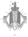
- Fig. 1 shows a centrifuge rotor supported by a vertical drive shaft 2.
- a separation chamber 3 is formed in which _ coaxially with the rotor _ a stack of frusto-conical separation discs 4 is arranged.
- the rotor 1 has a central inlet chamber 5 for a dispersion of components to be separated in the separation chamber 3, and a central outlet chamber 6 for a separated relatively light liquid.
- a stationary inlet tube 7 extends into the inlet chamber 5, and a stationary outlet member 8 extends into the outlet chamber 6.
- the rotor has an intermittently openable outlet 9 for a separated relatively heavy component, e.g. sludge which before separation constitutes the dispersed phase of the supplied dispersion.
- the inlet chamber 5 communicates with the separation chamber 3 through several radial channels 10 evenly distributed around the rotor axis. Through an overflow outlet 11 the separation chamber 3 communicates with the outlet chamber 6.
- Fig. 2 shows a separation disc 4 which on its upper side is provided with a number of radially extending ribs 12 intended to serve as spacing means between this separation disc and an adjacent separation disc in a centrifuge rotor according to fig. 1.
- the intended direction of rotation is shown by means of an arrow R.
- a dispersion supplied to the inlet chamber 5 is caused to rotate at the same speed as the rotor during its passage through the radial channels 10.
- the angular speed which the dispersion has reached in the area of the outer edges of the separation discs 4 will increase further, when the dispersion is forced to flow back towards the rotor axis between the separation discs.
- This increase of the angular speed depending on the fact that each part of the rotating dispersion is striving at maintaining its momentum, cannot be prevented by spacing members between the separation discs, such as ribs of the kind shown in Fig. 2.
- the geostrophic flow of the dispersion moving around the rotor axis i.e. substantially in the circumferential direction of the rotor, the formation of which, however, thus depends on the fact that the dispersion is forced to moving towards the rotor centre through the disc interspaces, experiences friction at the surfaces of the separation discs.
- a flow of liquid arises in a very thin layer closest to each disc surface, which flow has a substantially larger radially inwards directed component than the geostrophic flow, at least where the latter goes in the circumferential direction of the rotor.
- the thin layer usually is named Ekman layer.
- Fig. 3 illustrates how the radial flow may be distributed in different layers of an interspace between two conventional smooth separation discs 4a and 4b.
- the rotor axis is illustrated by a line 2a.
- the radial flow velocity is zero at the surfaces of the separation discs and substantially zero also in a large area 14 midway between the separation discs.
- a substantial radial flow exists only in two layers 15 and 16 close to the separation discs. These layers are the two above said so called Ekman layers. Substantially all dispersion to flow through the space between the separation discs 4a and 4b from their outer edges to their inner edges is thus forced to flow radially inwards in the layers 15 and 16.
- the thickness of each Ekman layer for most practical operation conditions is in the order of 1/10 of the distance between two adjacent separation discs.
- a substance dispersed in the dispersion e.g. small solids heavier than the carrying liquid will by the centrifugal force in the interspace between the separation discs strive at moving radially outwards toward the separation disc 4a and along it towards its outer edge.
- Such a flow of solids towards and along the separation disc 4a will be made difficult by the radially directed dispersion flow in the layer 15. Therefore, it would be desirable to accomplish, if possible, a different distribution of the radially inwards directed flow of the dispersion, so that it would be smaller in the area 15 and larger in the area 16.
- Such a desired flow distribution is shown by a dotted line in Fig. 3.
- the flow influencing members 17 have to be so formed that they give the upper side of each separation disc a rough surface structure, which prevents the formation of an Ekman layer thereon. Furthermore, they have to be so formed that even if they create a substantially larger friction resistance for the geostrophic flow along said upper side than a smooth surface would do, they should still not cause turbulence in a large part of the disc interspace. This would make it difficult or impossible for the intended separation of the dispersed substance to take place.
- the flow influencing members for the achievement of the desired effect, have to be so formed that the relation between the distance between adjacent members, seen in the circumferential direction of the rotor, and the distance between the separation discs, and the relation between the extent of each member in the circumferential direction of the rotor and the distance between the separation discs are both less than 2.
- Fig. 5 shows a section through parts of two adjacent separation discs 4c and 4d and the interspace therebetween.
- the upper side of the lower disc 4d has a number of flow influencing members 17 (see also Fig. 4) each with an extension l along the plate surface and a height h above the same.
- the distance between two adjacent flow influencing members is designated L and the distance between the separation discs is designated H .
- the direction of the geostrophic flow in the disc interspace is shown by an arrow G .
- Ekman layers Generally accepted theories about so called Ekman layers show that formation of an Ekman layer requires a geostrophic flow a predetermined minimum distance along a surface. This distance is relatively short.
- l/H and L/H should be less than 2 there will be formed no Ekman layer on the upper side of the separation disc 4d in connection with practically used parameters such as flow, viscosity, rotational speed, etc, for centrifugal separators of the kind here concerned.
- turbulence in the disc interspace above the flow influencing members 17 is avoided.
- each flow influencing member 17 may vary within wide limits according to the invention.
- the relation h/H i.e. the relation between the height of each member and the distance between the separation discs, should be in the range 0,2 - 0,5.
- the disc plate thickness usually is in the order of 0,5 - 1,0 mm, and the distance (H) between adjacent discs is in the order of 0,5 - 1,5 mm.
- flow influencing members formed according to the invention may have a height of for instance 0,1 - 0,7 mm and an extension along the separation disc surface and the geostrophic flow of for instance 0,2 - 3,0 mm.
- the invention has been described above applied to a case in which a dispersion contains a dispersed substance heavier than the continuous phase of the dispersion.
- the invention can also be used in connection with separation of a dispersed substance which is lighter than the continuous phase of the dispersion, e.g. separation of cream from milk.
- the flow influencing members should be situated on the underneath side of the conical separation discs, i.e. on the disc side from which the dispersed substance moves away owing to the centrifugal force during operation of the rotor.
- the upper or lower sides of the separation discs need not be covered entirely by flow influencing members.
- Flow influencing members are most important in that part of a disc interspace in which the strongest counter-flow can be expected between the separated dispersed substance and an Ekman layer formed as a consequence of the geostrophic flow.
Landscapes
- Centrifugal Separators (AREA)
Claims (6)
les éléments exerçant une action sur le flux (17) sont formés de telle manière que la relation (L/H) entre la distance (L) et les éléments exerçant une action sur le flux contigu, comme cela apparaît dans la direction circonférentielle du rotor, et la distance (H) entre les surfaces des disques de séparation contigus et la relation (L/H) entre le prolongement 1 de chaque élément exerçant une action sur le flux dans la direction circonférentielle du rotor et la distance (H) entre les surfaces de disques de séparation contigues sont toutes deux supérieures à zéro mais inférieures à deux, et
la surface du disque de séparation contigue en regard des éléments exerçant une action sur le flux (17) est constituée d'une manière connue per se de façon à établir une couche limite d'Ekman le long de celle-ci pendant le fonctionnement du rotor.
Applications Claiming Priority (2)
| Application Number | Priority Date | Filing Date | Title |
|---|---|---|---|
| SE8704871A SE457612B (sv) | 1987-12-07 | 1987-12-07 | Centrifugalseparator foer separering av ett aemne dispergerat i en vaetska |
| SE8704871 | 1987-12-07 |
Publications (2)
| Publication Number | Publication Date |
|---|---|
| EP0320105A1 EP0320105A1 (fr) | 1989-06-14 |
| EP0320105B1 true EP0320105B1 (fr) | 1991-03-20 |
Family
ID=20370513
Family Applications (1)
| Application Number | Title | Priority Date | Filing Date |
|---|---|---|---|
| EP88310245A Expired - Lifetime EP0320105B1 (fr) | 1987-12-07 | 1988-11-01 | Centrifugeur avec des moyens pour influencer le courant |
Country Status (8)
| Country | Link |
|---|---|
| US (1) | US4861329A (fr) |
| EP (1) | EP0320105B1 (fr) |
| JP (1) | JP2763307B2 (fr) |
| CN (1) | CN1016320B (fr) |
| BR (1) | BR8806350A (fr) |
| DE (1) | DE3862108D1 (fr) |
| ES (1) | ES2021146B3 (fr) |
| SE (1) | SE457612B (fr) |
Families Citing this family (33)
| Publication number | Priority date | Publication date | Assignee | Title |
|---|---|---|---|---|
| SE470348B (sv) * | 1992-06-16 | 1994-01-31 | Alfa Laval Separation Ab | Centrifugalseparator med separeringsskivor, vilka är försedda med strömningshinder |
| GB2274413B (en) * | 1993-01-23 | 1996-07-10 | Glacier Metal Co Ltd | Oil cleaning assemblies for engines |
| US5575912A (en) * | 1995-01-25 | 1996-11-19 | Fleetguard, Inc. | Self-driven, cone-stack type centrifuge |
| USRE38494E1 (en) | 1998-07-13 | 2004-04-13 | Phase Inc. | Method of construction for density screening outer transport walls |
| US6312610B1 (en) * | 1998-07-13 | 2001-11-06 | Phase Inc. | Density screening outer wall transport method for fluid separation devices |
| US6364822B1 (en) | 2000-12-07 | 2002-04-02 | Fleetguard, Inc. | Hero-turbine centrifuge with drainage enhancing baffle devices |
| US6755969B2 (en) | 2001-04-25 | 2004-06-29 | Phase Inc. | Centrifuge |
| US6805805B2 (en) * | 2001-08-13 | 2004-10-19 | Phase Inc. | System and method for receptacle wall vibration in a centrifuge |
| US6706180B2 (en) * | 2001-08-13 | 2004-03-16 | Phase Inc. | System for vibration in a centrifuge |
| EP1610879A4 (fr) * | 2003-03-11 | 2007-02-21 | Phase Inc | Centrifugeuse a decharge modulable des materiaux denses |
| US6971525B2 (en) * | 2003-06-25 | 2005-12-06 | Phase Inc. | Centrifuge with combinations of multiple features |
| ATE399594T1 (de) † | 2003-07-10 | 2008-07-15 | Westfalia Separator Gmbh | Trennteller und zentrifuge mit solchen trenntellern |
| WO2005011833A2 (fr) * | 2003-07-30 | 2005-02-10 | Phase Inc. | Systeme de filtration a nettoyage ameliore et separation de fluide dynamique |
| EP1663459A4 (fr) * | 2003-07-30 | 2007-11-07 | Phase Inc | Systeme de filtration et procede de separation de fluide dynamique |
| US7282147B2 (en) * | 2003-10-07 | 2007-10-16 | Phase Inc. | Cleaning hollow core membrane fibers using vibration |
| DE102008030028A1 (de) | 2008-06-13 | 2009-12-24 | Elringklinger Ag | Zentrifugalabscheider, insbesondere Ölabscheider für die Kurbelgehäuseentlüftung eines Hubkolben-Verbrennungsmotors |
| SE536493C2 (sv) | 2009-03-10 | 2013-12-27 | Alfa Laval Corp Ab | En modul innefattande en reaktorenhet |
| MX357126B (es) * | 2010-03-29 | 2018-06-27 | Newcastle Innovation Ltd | Dispositivo perfeccionado de separación por gravedad que utiliza canales poco espaciados. |
| DE102011050046A1 (de) * | 2011-05-02 | 2012-11-08 | Gea Mechanical Equipment Gmbh | Zentrifuge |
| PL2556895T3 (pl) * | 2011-08-10 | 2018-10-31 | Alfa Laval Corporate Ab | Tarcza rozdzielająca do separatora odśrodkowego i metoda wytwarzania tarczy rozdzielającej |
| AU2012344280B2 (en) * | 2011-11-28 | 2015-11-19 | Alfa Laval Corporate Ab | Centrifugal separator with anti-fouling properties |
| SE536671C2 (sv) | 2012-04-23 | 2014-05-13 | 3Nine Ab | Koniska skivelement till en rotor för centrifugalseparatorerjämte rotorer innehållande sådana skivelement |
| EP2730339B1 (fr) * | 2012-11-08 | 2018-07-25 | Alfa Laval Corporate AB | Séparateur centrifuge |
| EP2886217B1 (fr) * | 2013-12-20 | 2017-06-14 | Alfa Laval Corporate AB | Procédé de fabrication d'un disque de séparation et ledit disque |
| CN103736304B (zh) * | 2014-01-17 | 2015-11-04 | 昆明理工大学 | 一种离心浓密机 |
| GB2544797B (en) * | 2015-11-27 | 2020-04-29 | Swan Thomas & Co Ltd | Separation process for laminar materials, such as graphene |
| US20180008990A1 (en) * | 2016-07-07 | 2018-01-11 | Tobi D. Mengle | Centrifugal mechanical separator produced by additive manufacturing |
| EP3315204B1 (fr) | 2016-10-31 | 2019-05-08 | Alfa Laval Corporate AB | Empilement de disques de séparation |
| PL3315203T3 (pl) | 2016-10-31 | 2019-11-29 | Alfa Laval Corp Ab | Tarcza rozdzielająca dla separatora odśrodkowego |
| EP3315205A1 (fr) | 2016-10-31 | 2018-05-02 | Alfa Laval Corporate AB | Séparateur centrifuge |
| EP3398686B1 (fr) | 2017-05-02 | 2020-09-30 | Alfa Laval Corporate AB | Disque de séparation pour séparateur centrifuge |
| WO2021149239A1 (fr) * | 2020-01-24 | 2021-07-29 | 三菱化工機株式会社 | Dispositif de séparation centrifuge et plaque de séparation |
| EP4100166A1 (fr) * | 2020-02-06 | 2022-12-14 | POET Research, Inc. | Centrifugeuse, et systèmes et procédés associés |
Family Cites Families (8)
| Publication number | Priority date | Publication date | Assignee | Title |
|---|---|---|---|---|
| US1474379A (en) * | 1923-11-20 | robertson | ||
| SU539611A1 (ru) * | 1974-06-25 | 1976-12-25 | Проектный И Научно-Исследовательский Институт "Гипроникель" | Пакет сепарирующих тарелок к центрифуге |
| SE396022B (sv) * | 1975-03-18 | 1977-09-05 | Ivin Jury F | Rotor for en centrifugalseparator |
| JPS51118156A (en) * | 1975-04-08 | 1976-10-16 | Fuiroretodotsuchi Iuin Yuurii | Ball for centrifugal separator |
| SU797778A1 (ru) * | 1977-10-26 | 1981-01-23 | Предприятие П/Я А-7555 | Коническа тарелка к сепаратору |
| DE3201866C2 (de) * | 1982-01-22 | 1985-12-19 | Westfalia Separator Ag, 4740 Oelde | Schleudertrommel mit einem Kegeltellereinsatz |
| DE3426479C1 (de) * | 1984-07-18 | 1985-12-05 | Westfalia Separator Ag, 4740 Oelde | Zentrifuge zum Klaeren oder Trennen von Suspensionen |
| SE450093B (sv) * | 1985-10-30 | 1987-06-09 | Alfa Laval Separation Ab | Inloppsanordning vid centrifugalseparator |
-
1987
- 1987-12-07 SE SE8704871A patent/SE457612B/sv not_active IP Right Cessation
-
1988
- 1988-11-01 ES ES88310245T patent/ES2021146B3/es not_active Expired - Lifetime
- 1988-11-01 DE DE8888310245T patent/DE3862108D1/de not_active Expired - Lifetime
- 1988-11-01 EP EP88310245A patent/EP0320105B1/fr not_active Expired - Lifetime
- 1988-12-02 BR BR888806350A patent/BR8806350A/pt not_active IP Right Cessation
- 1988-12-06 US US07/280,714 patent/US4861329A/en not_active Expired - Lifetime
- 1988-12-07 JP JP63307971A patent/JP2763307B2/ja not_active Expired - Lifetime
- 1988-12-07 CN CN88108379A patent/CN1016320B/zh not_active Expired
Non-Patent Citations (1)
| Title |
|---|
| Derwent's abstract No 87573 E/41, SU 889 104 * |
Also Published As
| Publication number | Publication date |
|---|---|
| ES2021146B3 (es) | 1991-10-16 |
| JP2763307B2 (ja) | 1998-06-11 |
| SE457612B (sv) | 1989-01-16 |
| CN1016320B (zh) | 1992-04-22 |
| CN1035962A (zh) | 1989-10-04 |
| EP0320105A1 (fr) | 1989-06-14 |
| US4861329A (en) | 1989-08-29 |
| DE3862108D1 (de) | 1991-04-25 |
| BR8806350A (pt) | 1989-08-22 |
| SE8704871D0 (sv) | 1987-12-07 |
| JPH01297158A (ja) | 1989-11-30 |
Similar Documents
| Publication | Publication Date | Title |
|---|---|---|
| EP0320105B1 (fr) | Centrifugeur avec des moyens pour influencer le courant | |
| EP0221723B1 (fr) | Dispositif d'arrivée dans un séparateur centrifuge | |
| US5720705A (en) | Method for freeing a liquid from a substance dispersed therein and having a larger density than the liquid | |
| JP3473974B2 (ja) | デカンター型遠心分離装置 | |
| EP0468028B1 (fr) | Separateur centrifuge avec chambre d'admission contenant des disques annulaires | |
| EP0390899B1 (fr) | Separateur centrifuge | |
| CA2630691C (fr) | Puits d'injection dans un decanteur pour repartition d'ecoulement centrifuge et procede d'injection d'un influent dans un decanteur l'utilisant | |
| EP0824378B1 (fr) | Separateur centrifuge | |
| US5735789A (en) | Centrifugal separator | |
| US4350282A (en) | Self-purging centrifuge | |
| JP2597697B2 (ja) | 排出装置つき遠心分離機 | |
| EP0598099B1 (fr) | Separateur centrifuge | |
| EP0824379B1 (fr) | Separateur centrifuge | |
| US6033356A (en) | Centrifugal drum with increased flow resistance | |
| SE454954B (sv) | Centrifugalseparator innefattande ett i utmatningskammaren anordnat stationert utmatningsorgan i form av en huvudsakligen cirkuler skiva | |
| SU1169694A1 (ru) | Роторно-дисковый массообменный аппарат | |
| SU858924A1 (ru) | Сепаратор |
Legal Events
| Date | Code | Title | Description |
|---|---|---|---|
| PUAI | Public reference made under article 153(3) epc to a published international application that has entered the european phase |
Free format text: ORIGINAL CODE: 0009012 |
|
| AK | Designated contracting states |
Kind code of ref document: A1 Designated state(s): DE ES FR GB IT |
|
| 17P | Request for examination filed |
Effective date: 19890428 |
|
| 17Q | First examination report despatched |
Effective date: 19900514 |
|
| GRAA | (expected) grant |
Free format text: ORIGINAL CODE: 0009210 |
|
| AK | Designated contracting states |
Kind code of ref document: B1 Designated state(s): DE ES FR GB IT |
|
| ITF | It: translation for a ep patent filed | ||
| REF | Corresponds to: |
Ref document number: 3862108 Country of ref document: DE Date of ref document: 19910425 |
|
| ET | Fr: translation filed | ||
| PLBE | No opposition filed within time limit |
Free format text: ORIGINAL CODE: 0009261 |
|
| STAA | Information on the status of an ep patent application or granted ep patent |
Free format text: STATUS: NO OPPOSITION FILED WITHIN TIME LIMIT |
|
| 26N | No opposition filed | ||
| PGFP | Annual fee paid to national office [announced via postgrant information from national office to epo] |
Ref country code: GB Payment date: 20001101 Year of fee payment: 13 |
|
| PGFP | Annual fee paid to national office [announced via postgrant information from national office to epo] |
Ref country code: ES Payment date: 20001128 Year of fee payment: 13 |
|
| PG25 | Lapsed in a contracting state [announced via postgrant information from national office to epo] |
Ref country code: GB Free format text: LAPSE BECAUSE OF NON-PAYMENT OF DUE FEES Effective date: 20011101 |
|
| PG25 | Lapsed in a contracting state [announced via postgrant information from national office to epo] |
Ref country code: ES Free format text: LAPSE BECAUSE OF NON-PAYMENT OF DUE FEES Effective date: 20011102 |
|
| REG | Reference to a national code |
Ref country code: GB Ref legal event code: IF02 |
|
| GBPC | Gb: european patent ceased through non-payment of renewal fee |
Effective date: 20011101 |
|
| REG | Reference to a national code |
Ref country code: ES Ref legal event code: FD2A Effective date: 20021213 |
|
| PG25 | Lapsed in a contracting state [announced via postgrant information from national office to epo] |
Ref country code: IT Free format text: LAPSE BECAUSE OF NON-PAYMENT OF DUE FEES;WARNING: LAPSES OF ITALIAN PATENTS WITH EFFECTIVE DATE BEFORE 2007 MAY HAVE OCCURRED AT ANY TIME BEFORE 2007. THE CORRECT EFFECTIVE DATE MAY BE DIFFERENT FROM THE ONE RECORDED. Effective date: 20051101 |
|
| PGFP | Annual fee paid to national office [announced via postgrant information from national office to epo] |
Ref country code: DE Payment date: 20071025 Year of fee payment: 20 |
|
| PGFP | Annual fee paid to national office [announced via postgrant information from national office to epo] |
Ref country code: FR Payment date: 20071108 Year of fee payment: 20 |