EP0319358A1 - Trommelbremse mit selbsttätiger Nachstellung - Google Patents
Trommelbremse mit selbsttätiger Nachstellung Download PDFInfo
- Publication number
- EP0319358A1 EP0319358A1 EP88402837A EP88402837A EP0319358A1 EP 0319358 A1 EP0319358 A1 EP 0319358A1 EP 88402837 A EP88402837 A EP 88402837A EP 88402837 A EP88402837 A EP 88402837A EP 0319358 A1 EP0319358 A1 EP 0319358A1
- Authority
- EP
- European Patent Office
- Prior art keywords
- lever
- brake
- spacer
- segment
- segments
- Prior art date
- Legal status (The legal status is an assumption and is not a legal conclusion. Google has not performed a legal analysis and makes no representation as to the accuracy of the status listed.)
- Granted
Links
Images


Classifications
-
- F—MECHANICAL ENGINEERING; LIGHTING; HEATING; WEAPONS; BLASTING
- F16—ENGINEERING ELEMENTS AND UNITS; GENERAL MEASURES FOR PRODUCING AND MAINTAINING EFFECTIVE FUNCTIONING OF MACHINES OR INSTALLATIONS; THERMAL INSULATION IN GENERAL
- F16D—COUPLINGS FOR TRANSMITTING ROTATION; CLUTCHES; BRAKES
- F16D65/00—Parts or details
- F16D65/02—Braking members; Mounting thereof
- F16D65/10—Drums for externally- or internally-engaging brakes
-
- F—MECHANICAL ENGINEERING; LIGHTING; HEATING; WEAPONS; BLASTING
- F16—ENGINEERING ELEMENTS AND UNITS; GENERAL MEASURES FOR PRODUCING AND MAINTAINING EFFECTIVE FUNCTIONING OF MACHINES OR INSTALLATIONS; THERMAL INSULATION IN GENERAL
- F16D—COUPLINGS FOR TRANSMITTING ROTATION; CLUTCHES; BRAKES
- F16D65/00—Parts or details
- F16D65/38—Slack adjusters
- F16D65/40—Slack adjusters mechanical
- F16D65/52—Slack adjusters mechanical self-acting in one direction for adjusting excessive play
- F16D65/56—Slack adjusters mechanical self-acting in one direction for adjusting excessive play with screw-thread and nut
- F16D65/561—Slack adjusters mechanical self-acting in one direction for adjusting excessive play with screw-thread and nut for mounting within the confines of a drum brake
- F16D65/563—Slack adjusters mechanical self-acting in one direction for adjusting excessive play with screw-thread and nut for mounting within the confines of a drum brake arranged adjacent to service brake actuator, e.g. on parking brake lever, and not subjected to service brake force
Definitions
- the invention relates to a drum brake equipped with an automatic adjustment device taking into account the wear of the friction elements of the brake, so that the stroke of the brake motor remains practically unchanged despite this wear.
- a brake can be used either on a passenger vehicle or on a heavy vehicle.
- the invention relates to a drum brake such as that described in document US-A-4 222 467.
- This brake comprises a support plate on which two brake shoes are slidably mounted comprising friction linings . These linings are capable of being brought into contact with a rotating drum by a brake motor interposed between two adjacent ends of the segments.
- a spacer of variable length is interposed between the segments, close to the brake motor, to define a minimum spacing distance between the ends of the segments.
- a spring applies the segments against the spacer when the brake motor is not actuated.
- the automatic adjustment device controls an extension of the spacer.
- the spacer comprises a screw-nut assembly, the screw of which is integral with a toothed wheel.
- the subject of the invention is precisely a drum brake equipped with an automatic adjustment device directly controlling an extension of the spacer, this brake comprising means making it possible to neutralize the automatic adjustment device during sudden braking, it that is to say when the pressure applied to the segments by the brake motor exceeds a predetermined limit value.
- an automatically adjustable drum brake comprising a support plate on which two brake shoes are slidably mounted comprising friction elements capable of being brought into contact with a rotating drum by a brake motor interposed between two adjacent ends of the segments, a variable length spacer interposed between the segments near the brake motor, automatic adjustment means controlling an elongation of the spacer when an actuation of the brake motor removes said ends of the segments of a value greater than a predetermined functional clearance, and of the first elastic means tending to apply the segments against the spacer, characterized in that a first of the segments carries by a pivot axis a lever on which are normally in support the brake motor and the spacer, under the action of the first elastic means, the second means ns elastic bearing on the first segment to exert a force on the lever tending to maintain the latter in abutment against the first segment, the moment of this force relative to the pivot axis of the lever being opposite to the moment of the force exerted on the lever by the brake
- the brake motor and the spacer are supported on one of the segments by means of a lever pivotally mounted on this segment.
- the lever is normally immobilized on the segment which carries it by a spring.
- the moment of the force exerted by the brake motor on the lever with respect to its pivot axis exceeds the moment exerted in the opposite direction by the spring, the lever pivots on the segment.
- the lever is then kept in abutment on the spacer, so that no increase in the length of the latter occurs.
- the pivot axis of the lever on the first segment is located in a plane containing the axis of the brake motor, the latter being supported on a protuberance formed on the lever and located on the other side of said plane, compared to the spacer.
- the brake motor and the second elastic means are supported on the opposite ends of the lever, the latter being articulated on the first segment near the brake motor.
- the pivoting lever is a hand brake lever articulated on the first segment close to the brake motor, the second elastic means being interposed between the spacer and the first segment to maintain in permanently the spacer pressing on the handbrake lever.
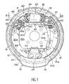
- the drum brake shown in FIG. 1 comprises a support plate 10 made up of an approximately flat disc 10a, extended at its periphery by a circular ring 10b.
- This plate 10 is intended to be secured to a fixed part of the vehicle, such as an axle flange.
- each of the segments 12 and 14 comprises an approximately planar core 12a, 14a, on which is fixed a rim 12b, 14b in the form of an arc of a circle supporting on its outer face a friction lining 16 and 18 respectively.
- the segments 12 and 14 are placed on the support plate 10 so that the outer envelopes of the linings 16 and 18 are located on the same circle whose axis coincides with the axis of the support plate 10.
- the linings 16 and 18 can come into contact with the interior surface of a brake drum 20 covering the two segments and shown in broken lines in FIG. 1.
- the drum 20 is mounted concentrically inside the ring 10b and it is attached to a rotating part such as a vehicle wheel.
- a brake motor 22, hydraulically controlled, is fixed on the disc 10a of the support plate, between two first adjacent ends of the segments 12 and 14.
- This brake motor 22 is provided with two pistons 24 and 26 which operate in opposition to so as to exert a push on the corresponding end of the core 12a, 14a of each of the segments, when the brake motor is actuated.
- a tension spring 30 is interposed between the ends of the cores of the segments between which the brake motor 22 is placed, in the immediate vicinity of the latter, to bring these ends closer to one another when the motor is not actuated .
- the two other ends of the segments 12 and 14 are held in abutment against the anchoring block 28 by means of a tension spring 32 interposed between the corresponding ends of the cores of the segments, in the immediate vicinity of this block.
- the segments 12 and 14 can be distinguished by the fact that the segment 12 is supported on the block d anchor 28 when in frictional contact with the drum, while the segment 14 bears on the piston 26 of the brake motor 22 under the same conditions. To take account of this difference, the segments 12 and 14 are respectively called “compressed segment” and “stretched segment”.
- a hand brake lever 34 is pivotally mounted by one of its ends on the end, for example, of the core of the stretched segment 14 adjacent to the brake motor 22, by means of an axis 36.
- the geometric axis of this axis 36 is located in the same plane as the axis of the brake motor 22 and it is oriented in a direction perpendicular to the latter axis.
- the end of a manual control cable 38 is fixed to the other end of the hand brake lever 34.
- the drum brake shown in Figure 1 further comprises a spacer 40 disposed between the segments 12 and 14, in the vicinity of the brake motor 22, approximately parallel to the axis of the latter.
- the spacer 40 has a variable length and is equipped with automatic adjustment means making it possible to increasing the length as the friction linings 16 and 18 wear out.
- the spacer 40 comprises two end pieces 40a and 40b in which are respectively formed a notch receiving the core of the segment 12 and a notch receiving the core of the segment 14 and the hand brake lever 34.
- Recesses formed at the spacer 40 on the inner edge of the core of each of the segments 12 and 14 keep the spacer in place.
- a tension spring 42 The ends of a tension spring 42 are hooked respectively on the core of the tensioned segment 14 and on the end piece 40b, so as to ensure permanent contact between the handbrake lever 34 and the bottom of the corresponding notch formed in the part 40b.
- This spring 42 thus indirectly applies a stamped part 34b of the handbrake lever against the inner edge of the core of the segment 14 supporting this lever.
- the part 40a is urged towards the core of the segment 12 by a tension spring 44 whose ends bear respectively on the core of the segment 12 and on the part 40a.
- the spacer 40 comprises a third part 40c, screwed onto the part 40a.
- the part 40a is extended on the side of the part 40b by a rod which slides in a hole formed in the adjacent end of the part 40b.
- the automatic adjustment means associated with the extensible spacer 40 comprise a toothed wheel formed at the periphery of the intermediate piece 40c and on which is engaged a pawl 40d formed at the end of an elastic blade whose opposite end is fixed on exhibit 40b.
- a member (not shown) fixed on the part 40a of the spacer cooperates with the spring leaf carrying the pawl 40d, so that a separation of the parts 40a and 40b of the spacer beyond a functional clearance determined allows the pawl 40d to rotate this toothed wheel in the direction corresponding to a extension of the spacer 40.
- a device is also provided for neutralizing the automatic adjustment means which have just been described, when the braking force exerted on the segments by the brake motor 22 exceeds a predetermined threshold.
- a lever 46 is pivotally mounted by an axis 48 on the end of the core 12a of the front segment adjacent to the brake motor 22.
- the geometric axis of this axis 48 is located in the same plane as the axis of the brake motor 22 and it is oriented perpendicular to this axis.
- the end of the lever 46 adjacent to the brake motor 22 is terminated by a protuberance 46a situated entirely on the other side of the plane passing through the geometrical axes of the brake motor 22 and the pivot axis 48, relative to the spacer 40.
- a tension spring 50 interposed between the core 12a of the segment 12 and the opposite end of the lever 46 tends to rotate the latter in a clockwise direction considering FIG. 2a, which has the effect of normally maintaining the lever 46 in a rest position determined by the abutment of the lever 46 on the segment 12.
- the lever 46 may have a stamped part (not shown) capable of coming to bear on the inner edge of the core 12a of the front segment. In this position of rest, the protuberance 46a protrudes beyond the end edge of the core of the segment 12 adjacent to the brake motor 22.
- the piston 24 is therefore supported on the protrusion 46a and normally spaced from the end edge of the soul of segment 12.
- FIG. 2b illustrates the case of powerful braking leading to applying to the ends of the segments adjacent to the brake motor excessive force, leading in a brake not equipped with the device of the invention to an over-adjustment.
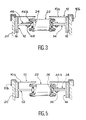
- the hand brake lever 34 then has at its end adjacent to the brake motor 22 a protuberance 34a which is located entirely on the other side of the plane passing through the geometric axes of the motor 22 and of the pivot axis 36, with respect to the spacer 40.
- the spring 42 applies the bottom of the notch formed at the end of the piece 40b of the spacer against the inner edge of the hand brake lever.
- the stamped part 34b (FIG. 1) of the handbrake lever is then applied against the inner edge of the core of the segment 14.
- the protrusion 34a protrudes towards the piston 26 of the engine 22 beyond the end edge of the core of the segment 14. Consequently, the piston 26 is supported on the protrusion 34a of the handbrake lever under the action of the spring 30 when the brake motor is released, while the end edge of the core of the segment 14 is spaced from the piston 26.
- the hand brake lever 34 is therefore subjected upon actuation of the brake motor 22 to two opposing forces tending to cause it to rotate in the opposite direction around its axis 36. More precisely, while the force indirectly exerted on the lever 34 by the spring 42, through the spacer 40, tends to rotate the handbrake lever counterclockwise around its axis 36 , the force exerted on the protuberance 34a of the hand brake lever by the piston 26 of the brake motor 22 tends to rotate this lever in the opposite direction.
- FIG. 4a shows that, in the case of a normal actuation of the brake, the moment of the force exerted by the piston 26 of the brake motor on the protuberance 34a of the hand brake lever around its axis 36 is less than the moment of the force exerted on this lever by the spring 42 around the same axis 36.
- the hand brake lever 34 remains in its rest position defined above, that is to say that it does not pivot around its axis 36. Consequently, when the actuation of the brake leads to spreading the ends of the segments adjacent to the brake motor 22 by a value greater than the functional clearance determined by the adjustment device associated with the spacer 40, a brake adjustment leading to an increase in the length of this spacer is ensured.
- the first embodiment described applies to a drum brake whether or not equipped with a hand brake lever.
- the lever 46 can be mounted either on one or the other of the segments.
- the two embodiments described can be used regardless of the nature of the automatic adjustment device making it possible to control the elongation of the spacer.
Landscapes
- Engineering & Computer Science (AREA)
- General Engineering & Computer Science (AREA)
- Mechanical Engineering (AREA)
- Braking Arrangements (AREA)
Applications Claiming Priority (2)
| Application Number | Priority Date | Filing Date | Title |
|---|---|---|---|
| FR8716617A FR2623864B1 (fr) | 1987-12-01 | 1987-12-01 | Frein a tambour a reglage automatique |
| FR8716617 | 1987-12-01 |
Publications (2)
| Publication Number | Publication Date |
|---|---|
| EP0319358A1 true EP0319358A1 (de) | 1989-06-07 |
| EP0319358B1 EP0319358B1 (de) | 1991-06-19 |
Family
ID=9357326
Family Applications (1)
| Application Number | Title | Priority Date | Filing Date |
|---|---|---|---|
| EP88402837A Expired - Lifetime EP0319358B1 (de) | 1987-12-01 | 1988-11-14 | Trommelbremse mit selbsttätiger Nachstellung |
Country Status (11)
| Country | Link |
|---|---|
| US (1) | US4903800A (de) |
| EP (1) | EP0319358B1 (de) |
| JP (1) | JPH01188731A (de) |
| KR (1) | KR970000868B1 (de) |
| AR (1) | AR240194A1 (de) |
| DE (1) | DE3863349D1 (de) |
| ES (1) | ES2022678B3 (de) |
| FR (1) | FR2623864B1 (de) |
| PT (1) | PT89128B (de) |
| TR (1) | TR23806A (de) |
| YU (1) | YU46888B (de) |
Cited By (1)
| Publication number | Priority date | Publication date | Assignee | Title |
|---|---|---|---|---|
| FR2929363A1 (fr) * | 2008-03-25 | 2009-10-02 | Bosch Gmbh Robert | Frein a tambour a dispositif de rattrapage automatique d'usure ameliore |
Families Citing this family (2)
| Publication number | Priority date | Publication date | Assignee | Title |
|---|---|---|---|---|
| US5553687A (en) * | 1994-06-02 | 1996-09-10 | Alliedsignal Aftermarket Europe | Method for assemblying and adjusting a drum brake |
| US5538112A (en) * | 1994-10-11 | 1996-07-23 | Kelsey-Hayes Company | Parking and emergancy brake actuating lever for drum brake assembly |
Citations (4)
| Publication number | Priority date | Publication date | Assignee | Title |
|---|---|---|---|---|
| US4222467A (en) * | 1979-02-02 | 1980-09-16 | The Bendix Corporation | Drum brake adjuster |
| EP0061961A1 (de) * | 1981-03-31 | 1982-10-06 | BENDIX France | Trommelbremse mit selbsttätiger Nachstellung |
| FR2507271A1 (fr) * | 1981-06-03 | 1982-12-10 | Lucas Industries Ltd | Dispositif de reglage automatique pour frein |
| WO1986001866A1 (en) * | 1984-09-14 | 1986-03-27 | Lucas Industries Public Limited Company | Self-actuating readjustment device for a brake |
Family Cites Families (1)
| Publication number | Priority date | Publication date | Assignee | Title |
|---|---|---|---|---|
| DE3244872A1 (de) * | 1982-12-03 | 1984-06-07 | Lucas Industries P.L.C., Birmingham, West Midlands | Selbsttaetige nachstellvorrichtung fuer eine bremse |
-
1987
- 1987-12-01 FR FR8716617A patent/FR2623864B1/fr not_active Expired - Lifetime
-
1988
- 1988-11-01 AR AR312603A patent/AR240194A1/es active
- 1988-11-14 DE DE8888402837T patent/DE3863349D1/de not_active Expired - Lifetime
- 1988-11-14 ES ES88402837T patent/ES2022678B3/es not_active Expired - Lifetime
- 1988-11-14 EP EP88402837A patent/EP0319358B1/de not_active Expired - Lifetime
- 1988-11-23 TR TR88/0847A patent/TR23806A/xx unknown
- 1988-11-24 KR KR1019880015507A patent/KR970000868B1/ko not_active IP Right Cessation
- 1988-11-25 YU YU216688A patent/YU46888B/sh unknown
- 1988-11-29 US US07/277,613 patent/US4903800A/en not_active Expired - Lifetime
- 1988-11-30 JP JP63301107A patent/JPH01188731A/ja active Pending
- 1988-11-30 PT PT89128A patent/PT89128B/pt not_active IP Right Cessation
Patent Citations (4)
| Publication number | Priority date | Publication date | Assignee | Title |
|---|---|---|---|---|
| US4222467A (en) * | 1979-02-02 | 1980-09-16 | The Bendix Corporation | Drum brake adjuster |
| EP0061961A1 (de) * | 1981-03-31 | 1982-10-06 | BENDIX France | Trommelbremse mit selbsttätiger Nachstellung |
| FR2507271A1 (fr) * | 1981-06-03 | 1982-12-10 | Lucas Industries Ltd | Dispositif de reglage automatique pour frein |
| WO1986001866A1 (en) * | 1984-09-14 | 1986-03-27 | Lucas Industries Public Limited Company | Self-actuating readjustment device for a brake |
Cited By (1)
| Publication number | Priority date | Publication date | Assignee | Title |
|---|---|---|---|---|
| FR2929363A1 (fr) * | 2008-03-25 | 2009-10-02 | Bosch Gmbh Robert | Frein a tambour a dispositif de rattrapage automatique d'usure ameliore |
Also Published As
| Publication number | Publication date |
|---|---|
| AR240194A1 (es) | 1990-02-28 |
| US4903800A (en) | 1990-02-27 |
| YU46888B (sh) | 1994-06-24 |
| FR2623864A1 (fr) | 1989-06-02 |
| DE3863349D1 (de) | 1991-07-25 |
| JPH01188731A (ja) | 1989-07-28 |
| PT89128B (pt) | 1993-11-30 |
| YU216688A (en) | 1990-08-31 |
| EP0319358B1 (de) | 1991-06-19 |
| FR2623864B1 (fr) | 1990-03-16 |
| ES2022678B3 (es) | 1991-12-01 |
| PT89128A (pt) | 1989-09-14 |
| TR23806A (tr) | 1990-09-13 |
| KR890010450A (ko) | 1989-08-08 |
| KR970000868B1 (ko) | 1997-01-20 |
Similar Documents
| Publication | Publication Date | Title |
|---|---|---|
| EP0599716A1 (de) | Bremsverfahren und -vorrichtung, insbesondere für Fahrräder | |
| WO1994010473A1 (fr) | Frein a tambour a actionnement mecanique | |
| EP1350040A1 (de) | Scheibenbremsenzylinder mit feststellbremsmechanismus | |
| EP0665926B1 (de) | Trommelbremse mit mechanischer betätigung | |
| EP0276611B1 (de) | Selbsttätig nachstellende Trommelbremse | |
| FR2977561A1 (fr) | Frein a patins pour bicyclette | |
| FR2726615A1 (fr) | Dispositif d'actionnement mecanique pour frein a tambour | |
| FR2927388A1 (fr) | Guidage d'un support de plaquette de frein a disque | |
| EP0734496B1 (de) | Automatisch nachstellbare strebe für eine trommelbremse | |
| EP0069657B1 (de) | Trommelbremse | |
| EP0319358B1 (de) | Trommelbremse mit selbsttätiger Nachstellung | |
| EP0278834B1 (de) | Trommelbremse mit selbsttätiger Nachstellung, verriegelt bei hohen Temperaturen | |
| EP0061961B1 (de) | Trommelbremse mit selbsttätiger Nachstellung | |
| EP0077726A1 (de) | Trommelbremse und Strebenteil für eine derartige Bremse | |
| EP0531178A1 (de) | Selbsttätige Nachstellvorrichtung für einen Bremsmechanismus | |
| EP0057639B1 (de) | Trommelbremse | |
| EP0385040B1 (de) | Auflaufbremse für ein gezogenes Fahrzeug, zum Beispiel ein Anhänger mit automatischer Unterdrückung des Bremsens beim Rückwärtsfahren | |
| FR2761654A1 (fr) | Dispositif de commande a lien souple et a rattrapage de jeu | |
| FR2464407A1 (fr) | Mecanisme de rattrapage automatique de l'usure pour freins a tambour | |
| EP0003452B1 (de) | Trommelbremse | |
| FR2849136A1 (fr) | Moteur de frein a disque a rattrapage d'usure, et frein a disque equipe d'un tel moteur | |
| FR2504627A1 (fr) | Frein a tambour a machoires internes actionnable hydrauliquement | |
| FR2704504A1 (fr) | Dispositif de traction tel un levier de commande de frein de stationnement en particulier pour véhicule automobile. | |
| EP0146444A1 (de) | Verankerung eines Verstrebungselementes, welches eine Einrichtung zur automatischen Regelung für ein Bremsbackensegment aufweist | |
| FR2536142A1 (fr) | Frein a tambour dont le dispositif de stationnement comprend un ensemble de leviers constitue d'une paire de bras |
Legal Events
| Date | Code | Title | Description |
|---|---|---|---|
| PUAI | Public reference made under article 153(3) epc to a published international application that has entered the european phase |
Free format text: ORIGINAL CODE: 0009012 |
|
| 17P | Request for examination filed |
Effective date: 19881119 |
|
| AK | Designated contracting states |
Kind code of ref document: A1 Designated state(s): DE ES FR GB IT |
|
| 17Q | First examination report despatched |
Effective date: 19900306 |
|
| RAP1 | Party data changed (applicant data changed or rights of an application transferred) |
Owner name: BENDIX EUROPE SERVICES TECHNIQUES S.A. |
|
| GRAA | (expected) grant |
Free format text: ORIGINAL CODE: 0009210 |
|
| AK | Designated contracting states |
Kind code of ref document: B1 Designated state(s): DE ES FR GB IT |
|
| GBT | Gb: translation of ep patent filed (gb section 77(6)(a)/1977) | ||
| REF | Corresponds to: |
Ref document number: 3863349 Country of ref document: DE Date of ref document: 19910725 |
|
| ITF | It: translation for a ep patent filed |
Owner name: STUDIO TORTA SOCIETA' SEMPLICE |
|
| PLBE | No opposition filed within time limit |
Free format text: ORIGINAL CODE: 0009261 |
|
| STAA | Information on the status of an ep patent application or granted ep patent |
Free format text: STATUS: NO OPPOSITION FILED WITHIN TIME LIMIT |
|
| 26N | No opposition filed | ||
| REG | Reference to a national code |
Ref country code: GB Ref legal event code: IF02 |
|
| PG25 | Lapsed in a contracting state [announced via postgrant information from national office to epo] |
Ref country code: IT Free format text: LAPSE BECAUSE OF NON-PAYMENT OF DUE FEES;WARNING: LAPSES OF ITALIAN PATENTS WITH EFFECTIVE DATE BEFORE 2007 MAY HAVE OCCURRED AT ANY TIME BEFORE 2007. THE CORRECT EFFECTIVE DATE MAY BE DIFFERENT FROM THE ONE RECORDED. Effective date: 20051114 |
|
| PGFP | Annual fee paid to national office [announced via postgrant information from national office to epo] |
Ref country code: ES Payment date: 20071127 Year of fee payment: 20 |
|
| PGFP | Annual fee paid to national office [announced via postgrant information from national office to epo] |
Ref country code: FR Payment date: 20071120 Year of fee payment: 20 Ref country code: GB Payment date: 20071123 Year of fee payment: 20 |
|
| PGFP | Annual fee paid to national office [announced via postgrant information from national office to epo] |
Ref country code: DE Payment date: 20080125 Year of fee payment: 20 |
|
| REG | Reference to a national code |
Ref country code: GB Ref legal event code: PE20 Expiry date: 20081113 |
|
| REG | Reference to a national code |
Ref country code: ES Ref legal event code: FD2A Effective date: 20081115 |
|
| PG25 | Lapsed in a contracting state [announced via postgrant information from national office to epo] |
Ref country code: ES Free format text: LAPSE BECAUSE OF EXPIRATION OF PROTECTION Effective date: 20081115 |
|
| PG25 | Lapsed in a contracting state [announced via postgrant information from national office to epo] |
Ref country code: GB Free format text: LAPSE BECAUSE OF EXPIRATION OF PROTECTION Effective date: 20081113 |
|
| PGRI | Patent reinstated in contracting state [announced from national office to epo] |
Ref country code: IT Effective date: 20090401 |
|
| PGFP | Annual fee paid to national office [announced via postgrant information from national office to epo] |
Ref country code: IT Payment date: 20071127 Year of fee payment: 20 |