EP0318644A2 - Computersteckverbinder mit einer den Schaltkreis automatisch schliessenden Vorrichtung - Google Patents
Computersteckverbinder mit einer den Schaltkreis automatisch schliessenden Vorrichtung Download PDFInfo
- Publication number
- EP0318644A2 EP0318644A2 EP88114018A EP88114018A EP0318644A2 EP 0318644 A2 EP0318644 A2 EP 0318644A2 EP 88114018 A EP88114018 A EP 88114018A EP 88114018 A EP88114018 A EP 88114018A EP 0318644 A2 EP0318644 A2 EP 0318644A2
- Authority
- EP
- European Patent Office
- Prior art keywords
- connector
- sheets
- printed circuit
- loop
- fixed
- Prior art date
- Legal status (The legal status is an assumption and is not a legal conclusion. Google has not performed a legal analysis and makes no representation as to the accuracy of the status listed.)
- Granted
Links
- 239000002184 metal Substances 0.000 claims abstract description 3
- 230000008878 coupling Effects 0.000 claims description 4
- 238000010168 coupling process Methods 0.000 claims description 4
- 238000005859 coupling reaction Methods 0.000 claims description 4
- 235000010603 pastilles Nutrition 0.000 claims description 2
- 239000011810 insulating material Substances 0.000 description 1
- 238000006467 substitution reaction Methods 0.000 description 1
Images
Classifications
-
- H—ELECTRICITY
- H01—ELECTRIC ELEMENTS
- H01R—ELECTRICALLY-CONDUCTIVE CONNECTIONS; STRUCTURAL ASSOCIATIONS OF A PLURALITY OF MUTUALLY-INSULATED ELECTRICAL CONNECTING ELEMENTS; COUPLING DEVICES; CURRENT COLLECTORS
- H01R13/00—Details of coupling devices of the kinds covered by groups H01R12/70 or H01R24/00 - H01R33/00
- H01R13/66—Structural association with built-in electrical component
- H01R13/70—Structural association with built-in electrical component with built-in switch
- H01R13/703—Structural association with built-in electrical component with built-in switch operated by engagement or disengagement of coupling parts, e.g. dual-continuity coupling part
- H01R13/7031—Shorting, shunting or bussing of different terminals interrupted or effected on engagement of coupling part, e.g. for ESD protection, line continuity
- H01R13/7032—Shorting, shunting or bussing of different terminals interrupted or effected on engagement of coupling part, e.g. for ESD protection, line continuity making use of a separate bridging element directly cooperating with the terminals
Definitions
- the present invention refers to a connector.
- looped network usually consists of a pair of electric wires, insulated from each other, and a wire mesh that wraps them and behaves as a protection screen against electromagnetic disturbances of the environment.
- This pair covers, going in and out, every station, linking them to each other like a loop, with no beginning and no end, although one of them often takes over certain control functions and the loop is then considered to begin and finish into it.
- the information received in a station moves along the loop in only one direction and is intercepted by the station to which it is directed or which needs it.
- a simple way to minimize, although not solving, these disadvantages, is to link in between the loop inlet and outlet connectors to the station by a cable having the adequate connectors at its ends, the loop continuity being thus recovered.
- Another way to solve this problem is to use a connector for both parts, with some mechanical device which links the pairs when beginning disconnecting, before losing the continuity of the contacts, so that the loop is not interrupted at any given moment.
- Spanish Utility Model No. 276,451 (priority of U.S.Patent No. 452,170) relates to an electric connector for the specific function of giving continuity in feeding a series of stations when disconnecting any one of them.
- Said connector apart from the structural complexity of the assembly, is based upon a plurality of elastic contact pawls which, on the one hand, are in permanent contact with a pair of bars, thereby establishing the connection of the corresponding station when such a connector receives the coupling of the respective connector of the station to be fed, whilst, when this station is disconnected, said contact pawls no longer contact then with the aforementioned pair or bars, said station not being. fed. Now then, at said disconnection moment, the said contact pawls enter into contact with some terminals through which feeding is continued on to the rest of stations, the former staying disconnected.
- Said connector requires special configuration pawls, as well as said bars and terminals, in order to achieve either connection, i.e., the direct connection to the station, or the continued feeding to the rest of stations, when said station is disconnected.
- the connector according to the invention far from being of the utmost complexity, is simply constituted, being based on two flat contact sheets associated to a printed circuit, which are driven by mere pushing of both pastilles which are displaced when coupling the mobile or flying connector which carries the corresponding feeding cable.
- the loop automatic closure device is related to the fixed connector.
- the fixed connector has a part thereof protected to a certain extent by a surrounding surface which forms part of a connector support or plate to which it is conveniently fixed.
- the electric contact sheets of the fixed connector are connected to a printed circuit which is fixed, in such a way that it can be dismounted, to the insulating block of the fixed connector.
- the connector stripes to which the shielded inlet and outlet cables of the loop are connected, are fixed to the printed circuit plate.
- the device according to the invention comprises flexible sheets which are fixed to the printed circuit by one of their sides, this being a double fixing; by the one hand, it is a mechanical fixing by means of a rivet, and by the other, and electric one, as each one of the sheets is connected to the printed circuit.
- the flexible sheets are connected to the printed circuit plate by the rear part or face, taking into account the connection direction of the connectors.
- the fingers of said piece run, in their turn, inside two facing drill holes performed in the printed circuit plate and by their free ends, the fingers are in contact with the flexible sheets.
- the flying connector i.e., the one which is arranged at the cable end, presses on the end of said piece, thereby elastically displacing the free ends of the sheets, the loop being closed through the working station, since the electric contact between the ends of the sheets and the fixed electric contacts of the printed circuit has been opened.
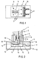
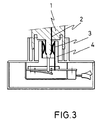
- Figures 2 and 3 represent the flying connector 1 provided with a contact sheet 2, which, in said figures, is in contact with the sheet 3 of the fixed connector 4.
- the fixed connector 4 is related to an outer support 5 which has a protection 6.
- a retaining element 7 which prevents from fortuitous electric disconnection cooperates in the coupling of the connectors.
- the fixed connector 4 has a printed circuit sheet 8 fixed by means of bolts 9.
- An insulating piece 10 is coupled to the fixed connector, which piece slides through drill holes performed in the insulating block of the fixed connector, as well as through facing drill holes performed in the printed circuit plate 8, so that the piece 10 is in contact or presses the flexible sheets 11 which open or close the loop.
- the sheets are fixed by one of their ends by rivets 12 to the printed circuit plate 8, whilst they are electrically connected by the printed circuit at points 13.
- Each one of the sheets is provided by its free end with a contact 14 facing the printed circuit contact 15.
- the printed circuit plate is provided with a connector strip 16 whereto the shielded cables 17 of the loop inlet and outlet are fixed.
- the device according to the invention which cons titutes the mechanical and electric operation of the piece 10 with respect to the sheets 11, is closed by a metal shield 18 and all that can be lodged in a case 19.
Landscapes
- Details Of Connecting Devices For Male And Female Coupling (AREA)
- Power-Operated Mechanisms For Wings (AREA)
- Selective Calling Equipment (AREA)
- Coupling Device And Connection With Printed Circuit (AREA)
- Projection Apparatus (AREA)
Priority Applications (1)
| Application Number | Priority Date | Filing Date | Title |
|---|---|---|---|
| AT88114018T ATE91048T1 (de) | 1987-12-03 | 1988-08-27 | Computersteckverbinder mit einer den schaltkreis automatisch schliessenden vorrichtung. |
Applications Claiming Priority (2)
| Application Number | Priority Date | Filing Date | Title |
|---|---|---|---|
| ES8703471 | 1987-12-03 | ||
| ES8703471 | 1987-12-03 |
Publications (3)
| Publication Number | Publication Date |
|---|---|
| EP0318644A2 true EP0318644A2 (de) | 1989-06-07 |
| EP0318644A3 EP0318644A3 (en) | 1990-05-23 |
| EP0318644B1 EP0318644B1 (de) | 1993-06-23 |
Family
ID=8253561
Family Applications (1)
| Application Number | Title | Priority Date | Filing Date |
|---|---|---|---|
| EP88114018A Expired - Lifetime EP0318644B1 (de) | 1987-12-03 | 1988-08-27 | Computersteckverbinder mit einer den Schaltkreis automatisch schliessenden Vorrichtung |
Country Status (6)
| Country | Link |
|---|---|
| US (1) | US4911650A (de) |
| EP (1) | EP0318644B1 (de) |
| AT (1) | ATE91048T1 (de) |
| CA (1) | CA1303159C (de) |
| DE (1) | DE3882022D1 (de) |
| DK (1) | DK456788A (de) |
Cited By (2)
| Publication number | Priority date | Publication date | Assignee | Title |
|---|---|---|---|---|
| GB2238672A (en) * | 1989-11-17 | 1991-06-05 | Amp Inc | Shunting device for use in electrical connectors |
| US5581434A (en) * | 1994-08-24 | 1996-12-03 | U.S. Philips Corporation | Apparatus including a transient voltage suppressor |
Families Citing this family (5)
| Publication number | Priority date | Publication date | Assignee | Title |
|---|---|---|---|---|
| FR2638576B1 (fr) * | 1988-10-27 | 1990-12-14 | Bull Sa | Ensemble universel de connexion, pour raccorder un terminal de traitement a un reseau de transmission de donnees |
| FR2683399A1 (fr) * | 1991-10-31 | 1993-05-07 | Itt Composants Instr | Ensemble de connexion du type a bouclage de circuit. |
| US6172310B1 (en) * | 2000-03-03 | 2001-01-09 | Hon Ahi Precision Ind. Co. Ltd. | Switching device for an electrical connector |
| JP2004158242A (ja) * | 2002-11-05 | 2004-06-03 | Alps Electric Co Ltd | 電子機器の電源供給装置 |
| US7431601B2 (en) * | 2006-12-18 | 2008-10-07 | Ernest A. Kussmaul | Automatic power line disconnect apparatus |
Family Cites Families (6)
| Publication number | Priority date | Publication date | Assignee | Title |
|---|---|---|---|---|
| US2197426A (en) * | 1936-11-05 | 1940-04-16 | Cinch Mfg Corp | Switch and radio tube socket assembly |
| US2308911A (en) * | 1939-08-23 | 1943-01-19 | Campodonice Carlo | Fire alarm device |
| US3512043A (en) * | 1967-11-09 | 1970-05-12 | Asea Ab | Means for short-circuiting the secondary circuit of a current transformer |
| US3781857A (en) * | 1972-02-18 | 1973-12-25 | J Stendig | Condition responsive receptacles |
| US4517419A (en) * | 1982-11-01 | 1985-05-14 | Gte Communication Systems Corp. | Cantilever spring telephone hookswitch adapted for printed wiring card mounting |
| IE55318B1 (en) * | 1982-12-22 | 1990-08-01 | Amp Inc | Shunt-protected electrical connector |
-
1988
- 1988-08-15 DK DK456788A patent/DK456788A/da not_active Application Discontinuation
- 1988-08-16 US US07/232,926 patent/US4911650A/en not_active Expired - Fee Related
- 1988-08-22 CA CA000575350A patent/CA1303159C/en not_active Expired - Lifetime
- 1988-08-27 AT AT88114018T patent/ATE91048T1/de not_active IP Right Cessation
- 1988-08-27 EP EP88114018A patent/EP0318644B1/de not_active Expired - Lifetime
- 1988-08-27 DE DE8888114018T patent/DE3882022D1/de not_active Expired - Lifetime
Cited By (3)
| Publication number | Priority date | Publication date | Assignee | Title |
|---|---|---|---|---|
| GB2238672A (en) * | 1989-11-17 | 1991-06-05 | Amp Inc | Shunting device for use in electrical connectors |
| GB2238672B (en) * | 1989-11-17 | 1994-04-20 | Amp Inc | Shunting device for use in electrical connectors |
| US5581434A (en) * | 1994-08-24 | 1996-12-03 | U.S. Philips Corporation | Apparatus including a transient voltage suppressor |
Also Published As
| Publication number | Publication date |
|---|---|
| DK456788A (da) | 1989-06-04 |
| ATE91048T1 (de) | 1993-07-15 |
| EP0318644A3 (en) | 1990-05-23 |
| CA1303159C (en) | 1992-06-09 |
| DK456788D0 (da) | 1988-08-15 |
| US4911650A (en) | 1990-03-27 |
| DE3882022D1 (de) | 1993-07-29 |
| EP0318644B1 (de) | 1993-06-23 |
Similar Documents
| Publication | Publication Date | Title |
|---|---|---|
| US5478249A (en) | Electrical connector and more specifically a charging connector | |
| GR3030758T3 (en) | Chain-type casing | |
| EP0318644A2 (de) | Computersteckverbinder mit einer den Schaltkreis automatisch schliessenden Vorrichtung | |
| CA1296786C (en) | Electric connector device | |
| GB2115237A (en) | Modular plug connector | |
| US4579412A (en) | Coded transfer plug system | |
| CA2235878C (en) | Switch connector | |
| CA1265178A (en) | Circuit breaker having improved stab assembly | |
| EP0844802A3 (de) | Telekommunikationsvorrichtung | |
| GB8901096D0 (en) | Subsea electrical conductive insert coupler | |
| US6099333A (en) | Customer bridge with automatic connect and disconnect features | |
| EP0068472B1 (de) | Zugangsmodul | |
| EP0296778A2 (de) | Vorrichtung zur Kontrolle der Steckverbindung eines elektrischen Moduls mit einer elektrischen Aufnahmevorrichtung | |
| US9312666B1 (en) | Panelboard/circuit breaker barrier interface | |
| ATE121897T1 (de) | Anschlussvorrichtung zum schalten oder trennen von leitungswegen in fernsprechvermittlungsanlagen. | |
| AU601557B2 (en) | Electronic module | |
| KR100195963B1 (ko) | 접속장치 | |
| US7025611B2 (en) | Connection device | |
| EP0798835A1 (de) | Schalttafel und Anschlusseinrichtung für elektrische Installationen mit modularen Einrichtungen | |
| CN217412248U (zh) | 一种弹片折线装置 | |
| CN212874400U (zh) | 一种操作按钮的锁定装置 | |
| EP1505841A1 (de) | Anschlussleiste für metallene Fernsprechkabel ausgelegt zum Einführen eines Zugangsmoduls | |
| CN117856058A (zh) | 便于装配的模块化配电设备和数字开关装置 | |
| JPS63149940A (ja) | 集線装置の支線構成方式 | |
| EP1261004B1 (de) | Verbindungseinrichtung für Fehlerstrommodul |
Legal Events
| Date | Code | Title | Description |
|---|---|---|---|
| PUAI | Public reference made under article 153(3) epc to a published international application that has entered the european phase |
Free format text: ORIGINAL CODE: 0009012 |
|
| AK | Designated contracting states |
Kind code of ref document: A2 Designated state(s): AT BE CH DE FR GB GR IT LI LU NL SE |
|
| PUAL | Search report despatched |
Free format text: ORIGINAL CODE: 0009013 |
|
| AK | Designated contracting states |
Kind code of ref document: A3 Designated state(s): AT BE CH DE FR GB GR IT LI LU NL SE |
|
| 17P | Request for examination filed |
Effective date: 19901024 |
|
| 17Q | First examination report despatched |
Effective date: 19920904 |
|
| GRAA | (expected) grant |
Free format text: ORIGINAL CODE: 0009210 |
|
| AK | Designated contracting states |
Kind code of ref document: B1 Designated state(s): AT BE CH DE FR GB GR IT LI LU NL SE |
|
| PG25 | Lapsed in a contracting state [announced via postgrant information from national office to epo] |
Ref country code: IT Free format text: LAPSE BECAUSE OF FAILURE TO SUBMIT A TRANSLATION OF THE DESCRIPTION OR TO PAY THE FEE WITHIN THE PRESCRIBED TIME-LIMIT;WARNING: LAPSES OF ITALIAN PATENTS WITH EFFECTIVE DATE BEFORE 2007 MAY HAVE OCCURRED AT ANY TIME BEFORE 2007. THE CORRECT EFFECTIVE DATE MAY BE DIFFERENT FROM THE ONE RECORDED. Effective date: 19930623 Ref country code: NL Effective date: 19930623 Ref country code: LI Effective date: 19930623 Ref country code: AT Effective date: 19930623 Ref country code: CH Effective date: 19930623 Ref country code: BE Effective date: 19930623 Ref country code: SE Effective date: 19930623 Ref country code: DE Effective date: 19930623 Ref country code: GR Free format text: LAPSE BECAUSE OF FAILURE TO SUBMIT A TRANSLATION OF THE DESCRIPTION OR TO PAY THE FEE WITHIN THE PRESCRIBED TIME-LIMIT Effective date: 19930623 Ref country code: FR Effective date: 19930623 |
|
| REF | Corresponds to: |
Ref document number: 91048 Country of ref document: AT Date of ref document: 19930715 Kind code of ref document: T |
|
| REF | Corresponds to: |
Ref document number: 3882022 Country of ref document: DE Date of ref document: 19930729 |
|
| PG25 | Lapsed in a contracting state [announced via postgrant information from national office to epo] |
Ref country code: LU Free format text: LAPSE BECAUSE OF NON-PAYMENT OF DUE FEES Effective date: 19930831 |
|
| PG25 | Lapsed in a contracting state [announced via postgrant information from national office to epo] |
Ref country code: GB Effective date: 19930923 |
|
| REG | Reference to a national code |
Ref country code: CH Ref legal event code: PL |
|
| EN | Fr: translation not filed | ||
| NLV1 | Nl: lapsed or annulled due to failure to fulfill the requirements of art. 29p and 29m of the patents act | ||
| PLBE | No opposition filed within time limit |
Free format text: ORIGINAL CODE: 0009261 |
|
| STAA | Information on the status of an ep patent application or granted ep patent |
Free format text: STATUS: NO OPPOSITION FILED WITHIN TIME LIMIT |
|
| GBPC | Gb: european patent ceased through non-payment of renewal fee |
Effective date: 19930923 |
|
| 26N | No opposition filed |