EP0318375B1 - Wärmeaustauscher mit Rippenrohrbündel und Gehäuse - Google Patents
Wärmeaustauscher mit Rippenrohrbündel und Gehäuse Download PDFInfo
- Publication number
- EP0318375B1 EP0318375B1 EP88402941A EP88402941A EP0318375B1 EP 0318375 B1 EP0318375 B1 EP 0318375B1 EP 88402941 A EP88402941 A EP 88402941A EP 88402941 A EP88402941 A EP 88402941A EP 0318375 B1 EP0318375 B1 EP 0318375B1
- Authority
- EP
- European Patent Office
- Prior art keywords
- bundle
- heat exchanger
- casing
- tenon
- carried
- Prior art date
- Legal status (The legal status is an assumption and is not a legal conclusion. Google has not performed a legal analysis and makes no representation as to the accuracy of the status listed.)
- Expired - Lifetime
Links
- 239000012530 fluid Substances 0.000 claims description 9
- 230000000295 complement effect Effects 0.000 claims description 6
- XLYOFNOQVPJJNP-UHFFFAOYSA-N water Substances O XLYOFNOQVPJJNP-UHFFFAOYSA-N 0.000 claims description 6
- 238000001816 cooling Methods 0.000 description 4
- 238000005192 partition Methods 0.000 description 3
- 238000009434 installation Methods 0.000 description 2
- 230000002528 anti-freeze Effects 0.000 description 1
- 238000005452 bending Methods 0.000 description 1
- 238000005219 brazing Methods 0.000 description 1
- 239000013529 heat transfer fluid Substances 0.000 description 1
- 239000000203 mixture Substances 0.000 description 1
- 230000035515 penetration Effects 0.000 description 1
- 230000000284 resting effect Effects 0.000 description 1
- 125000006850 spacer group Chemical group 0.000 description 1
- 239000013585 weight reducing agent Substances 0.000 description 1
Images
Classifications
-
- F—MECHANICAL ENGINEERING; LIGHTING; HEATING; WEAPONS; BLASTING
- F28—HEAT EXCHANGE IN GENERAL
- F28F—DETAILS OF HEAT-EXCHANGE AND HEAT-TRANSFER APPARATUS, OF GENERAL APPLICATION
- F28F1/00—Tubular elements; Assemblies of tubular elements
- F28F1/10—Tubular elements and assemblies thereof with means for increasing heat-transfer area, e.g. with fins, with projections, with recesses
- F28F1/12—Tubular elements and assemblies thereof with means for increasing heat-transfer area, e.g. with fins, with projections, with recesses the means being only outside the tubular element
- F28F1/24—Tubular elements and assemblies thereof with means for increasing heat-transfer area, e.g. with fins, with projections, with recesses the means being only outside the tubular element and extending transversely
- F28F1/32—Tubular elements and assemblies thereof with means for increasing heat-transfer area, e.g. with fins, with projections, with recesses the means being only outside the tubular element and extending transversely the means having portions engaging further tubular elements
-
- F—MECHANICAL ENGINEERING; LIGHTING; HEATING; WEAPONS; BLASTING
- F28—HEAT EXCHANGE IN GENERAL
- F28D—HEAT-EXCHANGE APPARATUS, NOT PROVIDED FOR IN ANOTHER SUBCLASS, IN WHICH THE HEAT-EXCHANGE MEDIA DO NOT COME INTO DIRECT CONTACT
- F28D1/00—Heat-exchange apparatus having stationary conduit assemblies for one heat-exchange medium only, the media being in contact with different sides of the conduit wall, in which the other heat-exchange medium is a large body of fluid, e.g. domestic or motor car radiators
- F28D1/02—Heat-exchange apparatus having stationary conduit assemblies for one heat-exchange medium only, the media being in contact with different sides of the conduit wall, in which the other heat-exchange medium is a large body of fluid, e.g. domestic or motor car radiators with heat-exchange conduits immersed in the body of fluid
- F28D1/04—Heat-exchange apparatus having stationary conduit assemblies for one heat-exchange medium only, the media being in contact with different sides of the conduit wall, in which the other heat-exchange medium is a large body of fluid, e.g. domestic or motor car radiators with heat-exchange conduits immersed in the body of fluid with tubular conduits
- F28D1/053—Heat-exchange apparatus having stationary conduit assemblies for one heat-exchange medium only, the media being in contact with different sides of the conduit wall, in which the other heat-exchange medium is a large body of fluid, e.g. domestic or motor car radiators with heat-exchange conduits immersed in the body of fluid with tubular conduits the conduits being straight
- F28D1/0535—Heat-exchange apparatus having stationary conduit assemblies for one heat-exchange medium only, the media being in contact with different sides of the conduit wall, in which the other heat-exchange medium is a large body of fluid, e.g. domestic or motor car radiators with heat-exchange conduits immersed in the body of fluid with tubular conduits the conduits being straight the conduits having a non-circular cross-section
- F28D1/05366—Assemblies of conduits connected to common headers, e.g. core type radiators
- F28D1/05383—Assemblies of conduits connected to common headers, e.g. core type radiators with multiple rows of conduits or with multi-channel conduits
-
- F—MECHANICAL ENGINEERING; LIGHTING; HEATING; WEAPONS; BLASTING
- F28—HEAT EXCHANGE IN GENERAL
- F28F—DETAILS OF HEAT-EXCHANGE AND HEAT-TRANSFER APPARATUS, OF GENERAL APPLICATION
- F28F9/00—Casings; Header boxes; Auxiliary supports for elements; Auxiliary members within casings
- F28F9/001—Casings in the form of plate-like arrangements; Frames enclosing a heat exchange core
- F28F9/002—Casings in the form of plate-like arrangements; Frames enclosing a heat exchange core with fastening means for other structures
-
- F—MECHANICAL ENGINEERING; LIGHTING; HEATING; WEAPONS; BLASTING
- F28—HEAT EXCHANGE IN GENERAL
- F28F—DETAILS OF HEAT-EXCHANGE AND HEAT-TRANSFER APPARATUS, OF GENERAL APPLICATION
- F28F2275/00—Fastening; Joining
- F28F2275/14—Fastening; Joining by using form fitting connection, e.g. with tongue and groove
-
- Y—GENERAL TAGGING OF NEW TECHNOLOGICAL DEVELOPMENTS; GENERAL TAGGING OF CROSS-SECTIONAL TECHNOLOGIES SPANNING OVER SEVERAL SECTIONS OF THE IPC; TECHNICAL SUBJECTS COVERED BY FORMER USPC CROSS-REFERENCE ART COLLECTIONS [XRACs] AND DIGESTS
- Y10—TECHNICAL SUBJECTS COVERED BY FORMER USPC
- Y10S—TECHNICAL SUBJECTS COVERED BY FORMER USPC CROSS-REFERENCE ART COLLECTIONS [XRACs] AND DIGESTS
- Y10S165/00—Heat exchange
- Y10S165/355—Heat exchange having separate flow passage for two distinct fluids
- Y10S165/442—Conduits
- Y10S165/443—Adjacent conduits with transverse air passages, e.g. radiator core type
Definitions
- the present invention relates to a heat exchanger, in particular for motor vehicles.
- DE-A-24 18 132 discloses a heat exchanger comprising a bundle of finned tubes on which is fixedly fixed on one of its lateral edges, a plate or cross-member allowing the bundle to be suspended or fixed to the vehicle body.
- a heat exchanger comprising at least one water box disposed at one end of a bundle of finned tubes traversed by a first fluid and an envelope traversed by a second fluid and surrounding said bundle.
- the exchanger thus formed is part of an installation used for cooling the air leaving a turbo-compressor and intended for supercharging the heat engine.
- the envelope may be a casing which generally provides a housing open at at least one end and into which the bundle is inserted by sliding, in the manner of a drawer.
- the casing is then closed by a cover so as to provide an enclosure, which, in the case of cooling of the charge air, comprises an inlet manifold and an outlet manifold of said air so that it arrives by the inlet tubing passes through the bundle that comprises the exchanger and can be cooled there.
- a bundle of tubes is provided. fins, provided with two water boxes and comprising hollow cylindrical sheaths of length slightly greater than the thickness of the bundle and traversing it right through, being placed from place to place along said bundle and parallel to a lateral face of the exchanger.
- the bundle is then slid, like a drawer, into a casing with a single open face to be assembled therewith, the ends of the sleeves coming into contact with the internal faces of the walls of said casing by forming spacers.
- These walls include, in accordance with the cylindrical sleeves, bores allowing the introduction of screws.
- the beam is immobilized in translation in the casing by the sleeves and locked in the latter by the screws and on the other hand the possible deformations of said walls are prevented by the same screws which form tie rods.
- the hollow cylindrical sleeves must be of large diameter in order to be able to resist the tightening force exerted by the screw and the nut.
- the placement of these sleeves requires on the one hand to occupy a location requiring the removal of a tube from the bundle and on the other hand to provide bores for receiving them through said bundle, these bores requiring to cut fins along their length.
- the present invention aims to remedy these drawbacks by simplifying and facilitating assembly of the bundle with the envelope or the casing containing it while retaining the performance of said exchanger.
- a heat exchanger in particular for motor vehicles, comprising at least one water box disposed at one end of a bundle of finned tubes traversed by a first fluid and an envelope, such as a limited casing. by walls surrounding said bundle and traversed by a second fluid, exchanger in which two faces of the bundle are adjacent to walls of the casing braced between them by assembly means positioning the bundle and carried by the latter, the exchanger is characterized in that the assembly means consist of sliding mutual engagement means carried respectively by the beam and by at least one of the walls of the casing, forming means for bracing and holding said walls.
- the means of mutual engagement consist of at least one assembly of the tenon-mortise type.
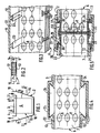
- FIGS 1 and 2 are shown a heat exchanger comprising a bundle 6 of tubes 8 with fins 7 and an envelope 2 containing it.
- the bundle 6 is provided with at least one water box 3 comprising inlet pipes 4 and outlet pipes 5 for the heat transfer fluid.
- the latter is slid, like a drawer, into the casing 2 here a casing 9 providing a housing 10 open at one end 11.
- This casing is of generally parallelepipedal shape delimited by two large parallel and opposite walls 12, 13, two small opposite walls and inclined towards one another 14, 15 and a bottom 16.
- the open end 11 is closed, after introduction of the bundle 6 into the housing 10, by a cover 17 carrying inlet pipes 18 and outlet pipes 19 for the fluid to be cooled.
- the assembly thus formed constitutes a device for cooling the air leaving a tubocompressor intended for supercharging the heat engine of a motor vehicle.
- the present invention proposes, as better visible to Figure 3, to remedy this drawback.
- the bundle 6 of finned tubes is linked to the casing 9 by means of mutual engagement.
- At least one front face of the beams 6, here both, comprises, over the entire length and parallel to a lateral face of said beam, at least one groove 21 or mortise, here in the form of a dovetail, practiced on the edge of the fins 7.
- an internal face 22 of at least one wall, here the two walls 12, 13, has at least one projection 23 with a tenon, of shape and arrangement complementary to those of the mortise 21 therefore in shape dovetail arranged opposite the mortise over the entire length of the wall considered.
- the harness 6 is assembled with the casing 9 as follows:
- the bundle 6 is presented opposite the open end 11 of the casing 9 in such a way that the mortises 21 of the bundle 6 are arranged in concordance with the tenons 23.
- the bundle is then introduced into the housing 10 by sliding the mortises 21 on the tenons 23 by mutual engagement until the complete penetration of said beam in said housing.
- the cover 17 is attached to the open end 11 for closing thereof.
- the beam is blocked in a first direction by the bottom 16 and the cover 17 and in the other two directions by the tenon-mortise assembly with complementary shapes.
- This assembly also makes it possible to avoid deformation of the walls 12, 13 of the casing 9, when the charge air is admitted, by creating a rigid connection between the front faces of the bundle 6 and the internal face of the walls 12 , 13, while allowing possible disassembly of the bundle 6 from the housing 10.
- the bundle 6 comprises at least one tenon 24, here in the form of a dovetail, disposed on at least one front face of said bundle, here the two faces.
- the tenon 24 can be part of either a projection each coming from the front edge of the fins 7 of the bundle 6 so as to form a longitudinal tenon of length equal to the length of the bundle and being parallel to a lateral face of the bundle 6, or an installation, during the development of the heat exchanger bundle, of at least one fin of greater thickness than the fins 7 and which has a projection forming a pin 24.
- This fin can be arranged, at regular intervals , in the stacking of fins 7, such as for example all twenty or thirty fins 7. Thus in practice it is sufficient at least one fin of greater thickness disposed in the middle of said beam.
- the walls 12, 13 of the casing 9 comprise, from their internal faces 22 and beyond their external faces, at least one groove 25 or mortise, of shape and arrangement complementary to those of the tenon 24, that is ie in the form of a dovetail, located in concordance with the tenon 24 and this, over the entire length of the wall considered.
- the assembly of the bundle 6 with the casing 9 is carried out in the same manner as that described for FIG. 3.
- Figure 5 shows another alternative embodiment of the assembly according to the invention.
- At least one tenon 26 is attached to at least one front face of the bundle 6.
- the latter is formed by a plate 50 which has a general T shape whose horizontal bar of the T is formed by two branches 27 , 28 parallel to the front face of the bundle and whose vertical bar is hollowed out from the intersection with the horizontal bar so as to leave one end open and whose base of said vertical bar forms a wall 29 parallel to said front face by being applied against it and connecting the branches 27, 28 respectively by perpendicular walls 30, 30 ⁇ to distance from the wall 29.
- This plate 50 attached to a front face of the bundle along its length and parallel to a lateral face, is fixed to the bundle by any suitable means such as brazing for example.
- each stud 26 through the heat exchanger bundle by any appropriate means such as for example a flat bar 31 consisting of a rectangular plate 32 which can pass into the space available between two fins and comprising, at one end, an enlarged part forming a support head 33.
- a flat bar 31 consisting of a rectangular plate 32 which can pass into the space available between two fins and comprising, at one end, an enlarged part forming a support head 33.
- the wall (s) 12, 13 carry at least one recess 34 or mortise of shape and arrangement complementary to that of the stud 26, that is to say in the shape of a T, erecting from their internal faces 22 projecting towards the outside of said walls and the horizontal bar of the T of which is constituted by a longitudinal groove 35 and the vertical bar by a longitudinal groove 36.
- the assembly of the bundle 6 in the casing 9 is identical to that described above.
- the casing 9 can be in two separate parts, each open at one end. So after having introduced the bundle of finned tubes into the first part by sliding the mortises or tenons carried by the beam along the tenons or mortises of said first part, it suffices to slide the tenons or mortises of the second part of the casing along the mortises or tenons carried by the beam.
- the front face of the bundle and the internal face of the wall each carry an identical tenon or a mortise and that there is provided an intermediate connecting part carrying forms of mutual engagement with the forms carried. by said front face and said internal face, and that the latter is slid either in the tenons or in the mortises so as to ensure the connection between the wall and the bundle.
Landscapes
- Engineering & Computer Science (AREA)
- Physics & Mathematics (AREA)
- Thermal Sciences (AREA)
- Mechanical Engineering (AREA)
- General Engineering & Computer Science (AREA)
- Geometry (AREA)
- Heat-Exchange Devices With Radiators And Conduit Assemblies (AREA)
Claims (10)
Applications Claiming Priority (2)
| Application Number | Priority Date | Filing Date | Title |
|---|---|---|---|
| FR8716451 | 1987-11-27 | ||
| FR8716451A FR2623895B1 (fr) | 1987-11-27 | 1987-11-27 | Echangeur de chaleur comportant un faisceau de tubes a ailettes et une enveloppe entourant ledit faisceau |
Publications (2)
| Publication Number | Publication Date |
|---|---|
| EP0318375A1 EP0318375A1 (de) | 1989-05-31 |
| EP0318375B1 true EP0318375B1 (de) | 1991-03-06 |
Family
ID=9357232
Family Applications (1)
| Application Number | Title | Priority Date | Filing Date |
|---|---|---|---|
| EP88402941A Expired - Lifetime EP0318375B1 (de) | 1987-11-27 | 1988-11-24 | Wärmeaustauscher mit Rippenrohrbündel und Gehäuse |
Country Status (5)
| Country | Link |
|---|---|
| US (1) | US4903762A (de) |
| EP (1) | EP0318375B1 (de) |
| DE (1) | DE3861951D1 (de) |
| ES (1) | ES2021452B3 (de) |
| FR (1) | FR2623895B1 (de) |
Families Citing this family (13)
| Publication number | Priority date | Publication date | Assignee | Title |
|---|---|---|---|---|
| DE4104432C1 (de) * | 1991-02-14 | 1992-04-09 | Erno Raumfahrttechnik Gmbh, 2800 Bremen, De | |
| DE10359806A1 (de) * | 2003-12-19 | 2005-07-14 | Modine Manufacturing Co., Racine | Wärmeübertrager mit flachen Rohren und flaches Wärmeübertragerrohr |
| FR2871738B1 (fr) * | 2004-06-21 | 2008-08-29 | Valeo Climatisation Sa | Boitier a etancheite locale de type "labyrinthe", pour une installation de chauffage, ventilation et/ou climatisation d'habitacle |
| DE102005053924B4 (de) * | 2005-11-11 | 2016-03-31 | Modine Manufacturing Co. | Ladeluftkühler in Plattenbauweise |
| CN101589286B (zh) * | 2007-01-23 | 2011-09-28 | 摩丁制造公司 | 热交换器和方法 |
| US20090250201A1 (en) | 2008-04-02 | 2009-10-08 | Grippe Frank M | Heat exchanger having a contoured insert and method of assembling the same |
| US8424592B2 (en) | 2007-01-23 | 2013-04-23 | Modine Manufacturing Company | Heat exchanger having convoluted fin end and method of assembling the same |
| DE102012206106A1 (de) * | 2012-04-13 | 2013-10-17 | Behr Gmbh & Co. Kg | Anordnung eines Ladeluftkühlers in einem Ansaugrohr |
| FR3004527B1 (fr) * | 2013-04-16 | 2015-05-15 | Fives Cryo | Echangeur de chaleur avec ensemble de liaison de tete de distribution a double fonction |
| JP6284409B2 (ja) * | 2014-04-09 | 2018-02-28 | 株式会社神戸製鋼所 | ガスクーラ |
| DE112017000586T5 (de) * | 2016-02-01 | 2018-12-13 | Dana Canada Corporation | Strukturell integraler wärmetauscher in einem kunststoffgehäuse |
| KR102723268B1 (ko) * | 2019-05-21 | 2024-10-31 | 한온시스템 주식회사 | 열교환기 |
| CN112414199B (zh) * | 2020-11-24 | 2021-12-03 | 浙江银轮机械股份有限公司 | 散热翅片构建方法及相关装置、散热翅片 |
Family Cites Families (7)
| Publication number | Priority date | Publication date | Assignee | Title |
|---|---|---|---|---|
| DE2418132C2 (de) * | 1974-04-13 | 1982-12-23 | Süddeutsche Kühlerfabrik Julius Fr. Behr GmbH & Co KG, 7000 Stuttgart | Wärmetauscher, insbesondere Kühler für Kraftfahrzeuge |
| FR2447529A1 (fr) * | 1979-01-26 | 1980-08-22 | Chausson Usines Sa | Echangeur tubulaire a lames contenues dans une enveloppe |
| US4303052A (en) * | 1980-03-24 | 1981-12-01 | The Garrett Corporation | Charge air cooler mounting arrangement |
| US4436145A (en) * | 1981-11-06 | 1984-03-13 | The Garrett Corporation | Charge air cooler mounting arrangement |
| FR2522401B1 (fr) * | 1982-02-26 | 1987-06-19 | Valeo | Echangeur de chaleur, en particulier radiateur d'un circuit de refroidissement de moteur d'un vehicule |
| DE3214453A1 (de) * | 1982-04-20 | 1983-10-20 | Süddeutsche Kühlerfabrik Julius Fr. Behr GmbH & Co KG, 7000 Stuttgart | Waermetauscher, insbesondere kuehler fuer kraftfahrzeuge |
| US4619313A (en) * | 1984-10-12 | 1986-10-28 | Touchstone Railway Supply & Mfg. Co., Inc. | Radiator frame unit |
-
1987
- 1987-11-27 FR FR8716451A patent/FR2623895B1/fr not_active Expired - Lifetime
-
1988
- 1988-11-22 US US07/274,905 patent/US4903762A/en not_active Expired - Lifetime
- 1988-11-24 ES ES88402941T patent/ES2021452B3/es not_active Expired - Lifetime
- 1988-11-24 EP EP88402941A patent/EP0318375B1/de not_active Expired - Lifetime
- 1988-11-24 DE DE8888402941T patent/DE3861951D1/de not_active Expired - Lifetime
Also Published As
| Publication number | Publication date |
|---|---|
| ES2021452B3 (es) | 1991-11-01 |
| EP0318375A1 (de) | 1989-05-31 |
| FR2623895B1 (fr) | 1990-07-06 |
| FR2623895A1 (fr) | 1989-06-02 |
| US4903762A (en) | 1990-02-27 |
| DE3861951D1 (de) | 1991-04-11 |
Similar Documents
| Publication | Publication Date | Title |
|---|---|---|
| EP0318375B1 (de) | Wärmeaustauscher mit Rippenrohrbündel und Gehäuse | |
| EP0481871B1 (de) | Flansch zum Verbinden von ein- und austretenden Rohren eines Verdampfers | |
| EP2402694A1 (de) | Kondensator insbesondere für ein Klimaanlagensystem eines Kraftfahrzeugs, und mit einem solchen Kondensator ausgestatteter Wärmetauscher | |
| FR2644376A1 (fr) | Procede d'elaboration d'un echangeur de chaleur a assemblage par soudage, en particulier par brasage, et echangeur s'y rapportant | |
| FR2748316A1 (fr) | Echangeur de chaleur a boite collectrice tubulaire et patte de fixation | |
| EP0519800A1 (de) | Vorrichtung zum Montieren zweier Leitungen auf zwei benachbarte Öffnungen von einer Endkammer eines Wärmetauschers | |
| FR2746491A1 (fr) | Echangeur de chaleur a plaques | |
| FR2748559A1 (fr) | Dispositif de fixation d'un groupe moto-ventilateur sur un echangeur de chaleur, notamment de vehicule automobile | |
| FR2761330A1 (fr) | Structure de module de partie avant d'une carrosserie de vehicule | |
| FR2747768A1 (fr) | Condenseur pour circuit de refrigeration, en particulier pour la climatisation d'un vehicule automobile | |
| FR2735856A1 (fr) | Procede de fixation de cloisons transversales dans une boite a fluide tubulaire d'echangeur de chaleur | |
| FR2779221A1 (fr) | Ensemble d'echangeurs de chaleur destine a un vehicule automobile | |
| EP1992892B1 (de) | Akkumulator für Klimatisierungsschaltkreis vom Typ interner Wärmetauscher und diesen enthaltender Schaltkreis | |
| FR2935912A1 (fr) | Procede d'assemblage et de brasage de deux pieces munies d'elements d'assemblage. | |
| WO2006035165A1 (fr) | Echangeur de chaleur comportant au moins une bride pour un collecteur de cet echangeur ainsi qu'un reservoir destine a equiper un tel echangeur | |
| FR2931544A1 (fr) | Module d'echange de chaleur comprenant au moins deux echangeurs de chaleur parcourus par un meme fluide caloporteur. | |
| EP3519755B1 (de) | Flüssigkeitssammelbehälter für einen wärmetauscher, zugehöriger wärmetauscher | |
| EP0757221A1 (de) | Wärmetauscher, insbesondere eine gelötete Ausführungsform für Kraftfahrzeug | |
| FR2788120A1 (fr) | Bati pour le support d'une centrale frigorifique et centrale frigorifique equipee d'un tel bati | |
| EP0611940A1 (de) | Vorrichtung mit zwei Wärmetauschern und einem Ausdehnungsgefäss | |
| EP0813013B1 (de) | Rohrleitungsverbindung mit Spannvorrichtung | |
| FR2921421A1 (fr) | Dispositif d'assemblage pour le maintien en position de montage d'un turbocompresseur suspendu sous un collecteur d'echappement | |
| WO2018142067A1 (fr) | Collecteur pour échangeur de chaleur | |
| WO2024017684A1 (fr) | Module thermique comportant un conduit de ventilation monté sur un échangeur thermique | |
| FR2753528A1 (fr) | Echangeur de chaleur a verrouillage de joue, notamment pour vehicule automobile |
Legal Events
| Date | Code | Title | Description |
|---|---|---|---|
| PUAI | Public reference made under article 153(3) epc to a published international application that has entered the european phase |
Free format text: ORIGINAL CODE: 0009012 |
|
| AK | Designated contracting states |
Kind code of ref document: A1 Designated state(s): DE ES GB IT |
|
| 17P | Request for examination filed |
Effective date: 19890706 |
|
| 17Q | First examination report despatched |
Effective date: 19891211 |
|
| GRAA | (expected) grant |
Free format text: ORIGINAL CODE: 0009210 |
|
| AK | Designated contracting states |
Kind code of ref document: B1 Designated state(s): DE ES GB IT |
|
| GBT | Gb: translation of ep patent filed (gb section 77(6)(a)/1977) | ||
| REF | Corresponds to: |
Ref document number: 3861951 Country of ref document: DE Date of ref document: 19910411 |
|
| ITF | It: translation for a ep patent filed | ||
| PLBE | No opposition filed within time limit |
Free format text: ORIGINAL CODE: 0009261 |
|
| STAA | Information on the status of an ep patent application or granted ep patent |
Free format text: STATUS: NO OPPOSITION FILED WITHIN TIME LIMIT |
|
| 26N | No opposition filed | ||
| PGFP | Annual fee paid to national office [announced via postgrant information from national office to epo] |
Ref country code: ES Payment date: 19981116 Year of fee payment: 11 |
|
| PGFP | Annual fee paid to national office [announced via postgrant information from national office to epo] |
Ref country code: GB Payment date: 19981117 Year of fee payment: 11 |
|
| PG25 | Lapsed in a contracting state [announced via postgrant information from national office to epo] |
Ref country code: GB Free format text: LAPSE BECAUSE OF NON-PAYMENT OF DUE FEES Effective date: 19991124 |
|
| PG25 | Lapsed in a contracting state [announced via postgrant information from national office to epo] |
Ref country code: ES Free format text: LAPSE BECAUSE OF NON-PAYMENT OF DUE FEES Effective date: 19991125 |
|
| GBPC | Gb: european patent ceased through non-payment of renewal fee |
Effective date: 19991124 |
|
| REG | Reference to a national code |
Ref country code: ES Ref legal event code: FD2A Effective date: 20001214 |
|
| PG25 | Lapsed in a contracting state [announced via postgrant information from national office to epo] |
Ref country code: IT Free format text: LAPSE BECAUSE OF NON-PAYMENT OF DUE FEES Effective date: 20051124 |
|
| PGFP | Annual fee paid to national office [announced via postgrant information from national office to epo] |
Ref country code: DE Payment date: 20071108 Year of fee payment: 20 |