EP0318346B1 - Befestigungsmittel für einen Sitzüberzug - Google Patents
Befestigungsmittel für einen Sitzüberzug Download PDFInfo
- Publication number
- EP0318346B1 EP0318346B1 EP88402762A EP88402762A EP0318346B1 EP 0318346 B1 EP0318346 B1 EP 0318346B1 EP 88402762 A EP88402762 A EP 88402762A EP 88402762 A EP88402762 A EP 88402762A EP 0318346 B1 EP0318346 B1 EP 0318346B1
- Authority
- EP
- European Patent Office
- Prior art keywords
- covering
- fixing device
- profile section
- situated
- slot
- Prior art date
- Legal status (The legal status is an assumption and is not a legal conclusion. Google has not performed a legal analysis and makes no representation as to the accuracy of the status listed.)
- Expired - Lifetime
Links
- 230000037431 insertion Effects 0.000 claims description 7
- 238000003780 insertion Methods 0.000 claims description 7
- 238000007688 edging Methods 0.000 claims 6
- 239000011248 coating agent Substances 0.000 description 4
- 238000000576 coating method Methods 0.000 description 4
- 238000009434 installation Methods 0.000 description 2
- 238000004519 manufacturing process Methods 0.000 description 2
- 230000003014 reinforcing effect Effects 0.000 description 2
- 239000004744 fabric Substances 0.000 description 1
- 239000006260 foam Substances 0.000 description 1
- 239000000463 material Substances 0.000 description 1
- 238000005192 partition Methods 0.000 description 1
- 230000002787 reinforcement Effects 0.000 description 1
- 238000007493 shaping process Methods 0.000 description 1
Images


Classifications
-
- A—HUMAN NECESSITIES
- A47—FURNITURE; DOMESTIC ARTICLES OR APPLIANCES; COFFEE MILLS; SPICE MILLS; SUCTION CLEANERS IN GENERAL
- A47C—CHAIRS; SOFAS; BEDS
- A47C31/00—Details or accessories for chairs, beds, or the like, not provided for in other groups of this subclass, e.g. upholstery fasteners, mattress protectors, stretching devices for mattress nets
- A47C31/02—Upholstery attaching means
- A47C31/023—Upholstery attaching means connecting upholstery to frames, e.g. by hooks, clips, snap fasteners, clamping means or the like
-
- B—PERFORMING OPERATIONS; TRANSPORTING
- B60—VEHICLES IN GENERAL
- B60N—SEATS SPECIALLY ADAPTED FOR VEHICLES; VEHICLE PASSENGER ACCOMMODATION NOT OTHERWISE PROVIDED FOR
- B60N2/00—Seats specially adapted for vehicles; Arrangement or mounting of seats in vehicles
- B60N2/58—Seat coverings
- B60N2/5816—Seat coverings attachments thereof
- B60N2/5825—Seat coverings attachments thereof by hooks, staples, clips, snap fasteners or the like
-
- Y—GENERAL TAGGING OF NEW TECHNOLOGICAL DEVELOPMENTS; GENERAL TAGGING OF CROSS-SECTIONAL TECHNOLOGIES SPANNING OVER SEVERAL SECTIONS OF THE IPC; TECHNICAL SUBJECTS COVERED BY FORMER USPC CROSS-REFERENCE ART COLLECTIONS [XRACs] AND DIGESTS
- Y10—TECHNICAL SUBJECTS COVERED BY FORMER USPC
- Y10S—TECHNICAL SUBJECTS COVERED BY FORMER USPC CROSS-REFERENCE ART COLLECTIONS [XRACs] AND DIGESTS
- Y10S160/00—Flexible or portable closure, partition, or panel
- Y10S160/15—Web-to-tube fasteners
-
- Y—GENERAL TAGGING OF NEW TECHNOLOGICAL DEVELOPMENTS; GENERAL TAGGING OF CROSS-SECTIONAL TECHNOLOGIES SPANNING OVER SEVERAL SECTIONS OF THE IPC; TECHNICAL SUBJECTS COVERED BY FORMER USPC CROSS-REFERENCE ART COLLECTIONS [XRACs] AND DIGESTS
- Y10—TECHNICAL SUBJECTS COVERED BY FORMER USPC
- Y10T—TECHNICAL SUBJECTS COVERED BY FORMER US CLASSIFICATION
- Y10T24/00—Buckles, buttons, clasps, etc.
- Y10T24/45—Separable-fastener or required component thereof [e.g., projection and cavity to complete interlock]
- Y10T24/45225—Separable-fastener or required component thereof [e.g., projection and cavity to complete interlock] including member having distinct formations and mating member selectively interlocking therewith
- Y10T24/45471—Projection having movable connection between components thereof or variable configuration
- Y10T24/45524—Projection having movable connection between components thereof or variable configuration including resiliently biased projection component or surface segment
- Y10T24/45545—Projection having movable connection between components thereof or variable configuration including resiliently biased projection component or surface segment forming total external surface of projection
- Y10T24/45586—Constructed from wire
Definitions
- the invention relates to a device for fixing a covering either to seats and in particular seats for a motor vehicle, or to a partition or wall or the like.
- the fixing of a covering generally requires a certain number of operations for preparing the covering, for example the chamfering, which must be carried out with precision, in addition the fixing elements must be produced and placed with precision, which results in an increase. manufacturing costs.
- the object of the present invention is to solve the problem of fixing a covering by making a device making it possible to fix it easily and quickly on any support, without any particular specification.
- the subject of the invention is a covering fixing device which comprises on the one hand a profile provided with longitudinal slots and, on the other hand, a bevelling wire folded in at least two points to form fixing clips intended for cooperate with the slots, each clip being generally situated in an inclined plane with respect to the axis of the bevelling thread and being liable to be deformed by twisting when it is inserted into a slot in the profile but resuming elastically after this insertion, its initial shape and an inclined position relative to the slot.
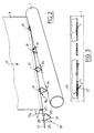
- a seat, seat or backrest element consisting of a hollow or profiled frame 1 on which a sheet 3 is fixed either by means of springs 5 (Fig. 1), or directly (Fig.4) .
- a lining 7, preferably made of elastic foam, is either placed on the ply surrounding the frame, or placed on the ply and the frame without covering the latter.
- the covering fixing device is made up on the one hand by the profile 1 in which are made longitudinal slots 15, coaxial but spaced, and, on the other hand, by a bevelling wire, of general reference 13 whose axis is parallel to that of the slots 15.
- the wire has several parts generally, but not necessarily, rectilinear 17,17a used to chamfer the coating 9 and at at least two points it is folded so as to form staples 19, 19a allowing the fixing of the covering 9 on the frame 1.
- the rectilinear parts 17, 17a are located on either side of a clip 19.
- the fastening clips 19, 19a protrude relative to the rectilinear parts 17, 17a and are generally located in an inclined plane relative to the axis of the bevelling wire.
- the staples have substantially the shape of a triangle whose rounded apex 21 is located in a plane parallel to the axis of the bevelling thread so as to facilitate the engagement of the staple in the slots 15 of the frame 1
- the sides 23, 25 of the triangle forming the clip move away in the opposite direction from this plane and are then folded towards one another in two wings 27, 29 so as to form the base of the triangle and constitute a base of retainer clip.
- the wings 27, 29 make an angle ⁇ with respect to the axis of the wire and come, after insertion, to bear on each side of the slot 15, thus ensuring the fixing of the system on the frame 1.
- the total length of the wings being greater than the width of the slot 15 but less than the length of the slot, this results in ease of assembly due to the fact that it is not necessary that the respective centers of the slots 15 and the clips 19, 19a etc ... be very specific.
- the covering 9 is prepared by making openings 31 of small dimensions relative to the length of the wings 27, 29, in which the staples 19 are introduced by tightening them laterally, then the staples are allowed to resiliently return to their initial shape. . Then the coating is turned around around the rectilinear parts 17, 17a etc ... and the coating is fixed relative to the latter by performing a longitudinal seam along the latter, which immobilizes the fixing device on the coating. In order for the covering to have practically its final dimensions, at least two of its ends must be provided with the bevelling wire.
- the ply 3 is also assembled on the frame 1 and covered with this ply and the frame of the lining 7.
- the prepared covering 9 is placed on this assembly, which is a particularly easy operation since the covering is not fixed at no point, making sure that the staples 19, 19a are roughly opposite the slots 15.
- the necessary seams for shaping the lining are made and then the staples 19, 19a are inserted into the slots 15 of the reinforcement 1 so as to fix and stretch the covering.
- any reinforcing element whose shape of straight section makes it possible to make slots therein may be suitable, for example a U-shaped section (FIG. .4A), or a section in a closed bracket (Fig.4B).
- the lining and the covering can almost completely surround the frame member, in this case the slots 15 are located on the part of the frame facing inwards.
- the fixing device of the present invention offers many advantages easy installation of the bevelling wire on the covering, inexpensive manufacture since it is not necessary to have great precision for the realization of the various elements and very easy installation which can even be carried out by an automaton.
Landscapes
- Engineering & Computer Science (AREA)
- Aviation & Aerospace Engineering (AREA)
- Transportation (AREA)
- Mechanical Engineering (AREA)
- Seats For Vehicles (AREA)
- Connection Of Plates (AREA)
- Coating Apparatus (AREA)
Claims (10)
- Vorrichtung zum Befestigen eines Überzugs, welche aufweist:
einerseits ein Profil (1), welches mit einer Folge longitutinaler Schlitze (15) versehen ist, und andererseits einen Befestigungsdraht (13), der an mindestens zwei Punkten gebogen ist, um Befestigungsklammern (19, 19a) zu bilden, um mit den Schlitzen zusammenzuwirken,
dadurch gekennzeichnet, daß
jede Klammer (19, 19a) sich allgemein in einer Ebene befindet, die bezüglich der Achse des Befestigungsdrahtes (13) geneigt ist, und durch Verschränkung hinsichtlich ihrer Einfügung in einen Schlitz (15) des Profils verformbar ist, aber elastisch nach dieser Einfügung ihre Anfangsform und eine geneigte Stellung bezüglich des Drahtes und des Schlitzes wieder einnimmt. - Vorrichtung zur Befestigung eines Überzugs nach Anspruch 1, dadurch gekennzeichnet, daß die Befestigungsklammern (19, 19a) im wesentlichen die Form eines Dreiecks mit abgerundeter Spitze (21) haben, dessen Basis (27, 29) sich in der geneigten Ebene befindet, während sich die Spitze (21) in einer Ebene parallel zur Achse des Befestigungsdrahtes befindet.
- Befestigungsvorrichtung nach einem der Ansprüche 1 und 2, dadurch gekennzeichnet, daß die Schlitze (15) des Profils (1) parallel zu dem Befestigungsdraht sind.
- Befestigungsvorrichtung nach einem der Ansprüche 1 bis 3, dadurch gekennzeichnet, daß nach Einfügen die Basis (27, 29) jeder Befestigungsklammer (19, 19a) gegen die Innenfläche des Profils (1) drückt, und zwar auf beiden Seiten des Aufnahmeschlitzes (15).
- Befestigungsvorrichtung nach einem der Ansprüche 2 bis 4, dadurch gekennzeichnet, daß die Länge der Basis (27, 29) des Dreiecks der Klammer kürzer ist als die Länge des Schlitzes.
- Befestigungsvorrichtung nach einem der vorhergehenden Ansprüche, dadurch gekennzeichnet, daß die Klammern (19, 19a) sich zwischen geraden Teilen (17, 17a) des Befestigungsdrahtes befinden.
- Befestigungsvorrichtung nach einem der Ansprüche 1 bis 6, dadurch gekennzeichnet, daß der Überzug (9) um die geraden Teile (17, 17a) des Befestigungsdrahtes gewickelt ist und daß die Befestigungsklammern (19, 19a) durch die Öffnungen (31) des Überzugs hervorstehen.
- Sitzelement, welches eine hohle Bewehrung (1) aufweist, auf welcher ein Mantel (3) befestigt ist, der eine Auskleidung (5) stützt, welche mit einem Überzug (9) versehen ist, dadurch gekennzeichnet, daß der Überzug (9) durch eine Befestigungsvorrichtung nach einem der vorhergehenden Ansprüche befestigt ist, wobei das Profil aus einem Element der Bewehrung des Sitzes gebildet ist.
- Sitzelement nach Anspruch 8, dadurch gekennzeichnet, daß die Auskleidung (5) und der Überzug (9) fast vollständig das Bewehrungselement (1) umschließen und daß die Schlitze (15) sich auf dem Teil des Bewehrungselements befinden, welches zu dem Inneren des Sitzes weist.
- Sitzelement nach Anspruch 8, dadurch gekennzeichnet, daß der Überzug (9) sich bis über die Auskleidung hinaus verlängert und einen Teil des Profils überdeckt.
Applications Claiming Priority (2)
| Application Number | Priority Date | Filing Date | Title |
|---|---|---|---|
| FR8716287 | 1987-11-24 | ||
| FR8716287A FR2623382B1 (fr) | 1987-11-24 | 1987-11-24 | Dispositif de fixation d'un revetement notamment un revetement de siege |
Publications (2)
| Publication Number | Publication Date |
|---|---|
| EP0318346A1 EP0318346A1 (de) | 1989-05-31 |
| EP0318346B1 true EP0318346B1 (de) | 1993-01-27 |
Family
ID=9357113
Family Applications (1)
| Application Number | Title | Priority Date | Filing Date |
|---|---|---|---|
| EP88402762A Expired - Lifetime EP0318346B1 (de) | 1987-11-24 | 1988-11-03 | Befestigungsmittel für einen Sitzüberzug |
Country Status (8)
| Country | Link |
|---|---|
| US (1) | US4872724A (de) |
| EP (1) | EP0318346B1 (de) |
| AR (1) | AR246414A1 (de) |
| BR (1) | BR8806151A (de) |
| CA (1) | CA1296435C (de) |
| DE (1) | DE3877916T2 (de) |
| ES (1) | ES2037264T3 (de) |
| FR (1) | FR2623382B1 (de) |
Families Citing this family (22)
| Publication number | Priority date | Publication date | Assignee | Title |
|---|---|---|---|---|
| GB8822638D0 (en) * | 1988-09-27 | 1988-11-02 | Gen Motors Corp | Knitting method |
| GB2253219B (en) * | 1991-03-01 | 1994-12-07 | Gen Motors Corp | Fabric structure incorporating an attachment wire |
| US5338092A (en) * | 1993-03-19 | 1994-08-16 | Lear Seating Corporation | Drawstring seat cover |
| AU6786994A (en) * | 1993-05-12 | 1994-12-12 | N.F.A. Corp. | Seat, upholstery attachment means, and upholstering method |
| US5716096A (en) * | 1993-09-20 | 1998-02-10 | Lear Corporation | Drawstring seat cover for attachment to a seat |
| FR2727236B1 (fr) * | 1994-11-22 | 1996-12-27 | Alcatel Mobile Comm France | Detection d'activite vocale |
| GB9611879D0 (en) * | 1996-06-07 | 1996-08-07 | Mckechnie Uk Ltd | Stacking containers |
| US5716101A (en) * | 1996-07-12 | 1998-02-10 | Bjip, Inc. | Seat rail attachment device |
| US6330898B1 (en) * | 1999-11-29 | 2001-12-18 | Tony Chang | Rain canopy apparatus for a stroller |
| EP1746916A1 (de) * | 2004-05-19 | 2007-01-31 | Shaf S.P.A. | Anordnung zum entfernbaren befestigen eines stoffs in einem einrichtungsgegenstand |
| US7837260B2 (en) * | 2005-05-31 | 2010-11-23 | Milsco Manufacturing Company | Vehicle seat assembly system |
| DE102008009981A1 (de) * | 2008-02-19 | 2009-08-20 | Seatex Ag | Abspanneinrichtung für Sitze |
| CN102505337B (zh) * | 2011-10-11 | 2015-03-04 | 天津市金纬纺织机械有限公司 | 衬绳成型机 |
| JP6232327B2 (ja) * | 2014-03-27 | 2017-11-15 | 日本発條株式会社 | シートカバーの吊り込み構造 |
| US11014675B2 (en) * | 2014-04-03 | 2021-05-25 | Franklin Products, Inc. | Lightweight upholstery cover with edge attachment |
| US11097640B2 (en) * | 2014-04-03 | 2021-08-24 | Franklin Products, Inc. | Method and articles for attaching upholstery covers and other flexible material |
| US10463170B2 (en) | 2015-09-09 | 2019-11-05 | Kids Ii, Inc. | Collapsible play yard |
| USD866995S1 (en) | 2016-09-08 | 2019-11-19 | Kids2, Inc. | Play yard |
| CA2986722A1 (en) * | 2017-11-27 | 2019-05-27 | Katya Ponich | Attachable/detachable lap blankets for seat occupants |
| CN111248681B (zh) * | 2019-07-15 | 2023-04-07 | 锐迈机械科技(吴江)有限公司 | 一种功能沙发铁架的支撑组件 |
| CN212165377U (zh) * | 2019-12-11 | 2020-12-18 | 迪锐克斯科技无锡有限公司 | 一种防止脱落和便于安装的嵌入式座椅网布 |
| US11142322B1 (en) * | 2020-08-31 | 2021-10-12 | B/E Aerospace, Inc. | Attachment assembly for a dress cover and a cushion of an aircraft seat |
Family Cites Families (8)
| Publication number | Priority date | Publication date | Assignee | Title |
|---|---|---|---|---|
| CA474512A (en) * | 1951-06-19 | M. Scanlon James | Snap fasteners | |
| US2322836A (en) * | 1940-07-08 | 1943-06-29 | Chrysler Corp | Trim material |
| US2938249A (en) * | 1956-11-05 | 1960-05-31 | Gen Motors Corp | Weather strip assembly |
| US3048910A (en) * | 1960-06-29 | 1962-08-14 | Chrysler Corp | Snap-on clip structure |
| US3499257A (en) * | 1967-12-29 | 1970-03-10 | Johns Manville | Ceiling structure |
| GB1376658A (en) * | 1972-03-20 | 1974-12-11 | Universal Oil Prod Co | Vehicle seat |
| FR2528681A1 (fr) * | 1982-06-16 | 1983-12-23 | Citroen Sa | Siege, notamment pour vehicules automobiles |
| US4789201A (en) * | 1987-09-08 | 1988-12-06 | Hoover Universal, Inc. | Seat trim attachment strip |
-
1987
- 1987-11-24 FR FR8716287A patent/FR2623382B1/fr not_active Expired - Fee Related
-
1988
- 1988-10-27 AR AR88312320A patent/AR246414A1/es active
- 1988-11-03 ES ES198888402762T patent/ES2037264T3/es not_active Expired - Lifetime
- 1988-11-03 EP EP88402762A patent/EP0318346B1/de not_active Expired - Lifetime
- 1988-11-03 DE DE8888402762T patent/DE3877916T2/de not_active Expired - Fee Related
- 1988-11-10 US US07/269,331 patent/US4872724A/en not_active Expired - Fee Related
- 1988-11-14 CA CA000582909A patent/CA1296435C/en not_active Expired - Lifetime
- 1988-11-23 BR BR888806151A patent/BR8806151A/pt unknown
Also Published As
| Publication number | Publication date |
|---|---|
| CA1296435C (en) | 1992-02-25 |
| FR2623382B1 (fr) | 1991-05-03 |
| AR246414A1 (es) | 1994-08-31 |
| FR2623382A1 (fr) | 1989-05-26 |
| DE3877916D1 (de) | 1993-03-11 |
| EP0318346A1 (de) | 1989-05-31 |
| US4872724A (en) | 1989-10-10 |
| BR8806151A (pt) | 1989-08-15 |
| ES2037264T3 (es) | 1993-06-16 |
| DE3877916T2 (de) | 1993-05-19 |
Similar Documents
| Publication | Publication Date | Title |
|---|---|---|
| EP0318346B1 (de) | Befestigungsmittel für einen Sitzüberzug | |
| EP0687432B1 (de) | Sitzgestellelement, Gegenstand unter Verwendung desselben und seine Anwendung insbesondere in einem Fahrzeugsitz | |
| FR2751722A1 (fr) | Dispositif de fixation destine a assujettir un organe de jonction de tubes a une plaquette qu'il traverse par une ouverture associee | |
| FR2757604A1 (fr) | Dispositif pour raccorder deux elements de conduites en forme de tubes | |
| FR2773752A1 (fr) | Dossier de siege a face arriere rentrante | |
| EP1787878A1 (de) | Befestigungsvorrichtung, insbesondere einer Betätigungsstange eines Bremskraftverstärkers an ein Bremspedal eines Kraftfahrzeuges | |
| EP0444996A1 (de) | Vorrichtung für die Befestigung einer Lenksäule an den Aufbau eines Kraftfahrzeuges | |
| FR2672015A1 (fr) | Dispositif de montage d'un boitier, notamment d'un appareil de chauffage et/ou de climatisation, sur la carrosserie d'un vehicule automobile. | |
| FR2837780A1 (fr) | Procede d'assemblage d'un module d'equipement et d'un element d'habillage de vehicule automobile et agencement pour un tel assemblage | |
| FR2593052A1 (fr) | Siege, notamment pour vehicule automobile. | |
| EP0780268A1 (de) | Befestigungssystem für eine Kraftfahrzeuginnenverkleidung | |
| FR2861660A1 (fr) | Armature de siege d'automobile comportant un assemblage d'une platine sur un tube | |
| FR2973755A1 (fr) | Dispositif et procede de montage d'un mecanisme d'essuie-vitre | |
| FR2861659A1 (fr) | Armature de sige d'automobile comportant un assemblage d'une platine sur un tube | |
| FR2791742A1 (fr) | Dispositif de fixation rapide d'une bague dans une echancrure d'une piece support | |
| EP0746692B1 (de) | Klemmvorrichtung zur befestigung eines elements an einem blechteil eines fahrzeugs, sowie herstellungsverfahren dafür | |
| EP0937907B1 (de) | Vorrichtung zum Verbinden des Ankerkerns eines elastischen Gelenks mit einem Aussenteil | |
| EP0751036B1 (de) | Metalltubenteil und Sitzrückenlehne für Kraftfahrzeugsitzrückenlehne mit einem solchen Teil | |
| FR2765842A1 (fr) | Systeme de fixation d'une gaine de maintien d'un appuie-tete sur une armature de dossier d'un siege de vehicule automobile | |
| FR2690970A1 (fr) | Attache pour le maintien de plusieurs canalisations, câbles ou analogues. | |
| FR2694351A1 (fr) | Dispositif perfectionné d'assemblage à emboîtement et verrouillage et son application aux sièges d'automobiles. | |
| FR2770470A1 (fr) | Element de siege pour vehicule automobile et organe destine a l'accrochage d'une coiffe de cet element sur une armature de cet element | |
| FR2737991A1 (fr) | Siege a maintiens lateraux pour automobile | |
| FR2562055A1 (fr) | Assise de siege, notamment pour vehicules automobiles | |
| EP1254038B1 (de) | Innenausstattungsteil für den fahrgastraum eines fahrzeugs |
Legal Events
| Date | Code | Title | Description |
|---|---|---|---|
| PUAI | Public reference made under article 153(3) epc to a published international application that has entered the european phase |
Free format text: ORIGINAL CODE: 0009012 |
|
| AK | Designated contracting states |
Kind code of ref document: A1 Designated state(s): BE DE ES GB IT NL SE |
|
| 17P | Request for examination filed |
Effective date: 19890424 |
|
| RAP1 | Party data changed (applicant data changed or rights of an application transferred) |
Owner name: CESA COMPAGNIE EUROPEENNE DE SIEGES POUR AUTOMOBIL |
|
| 17Q | First examination report despatched |
Effective date: 19920206 |
|
| GRAA | (expected) grant |
Free format text: ORIGINAL CODE: 0009210 |
|
| AK | Designated contracting states |
Kind code of ref document: B1 Designated state(s): BE DE ES GB IT NL SE |
|
| ITF | It: translation for a ep patent filed | ||
| GBT | Gb: translation of ep patent filed (gb section 77(6)(a)/1977) |
Effective date: 19930208 |
|
| REF | Corresponds to: |
Ref document number: 3877916 Country of ref document: DE Date of ref document: 19930311 |
|
| REG | Reference to a national code |
Ref country code: ES Ref legal event code: FG2A Ref document number: 2037264 Country of ref document: ES Kind code of ref document: T3 |
|
| PLBE | No opposition filed within time limit |
Free format text: ORIGINAL CODE: 0009261 |
|
| STAA | Information on the status of an ep patent application or granted ep patent |
Free format text: STATUS: NO OPPOSITION FILED WITHIN TIME LIMIT |
|
| 26N | No opposition filed | ||
| EAL | Se: european patent in force in sweden |
Ref document number: 88402762.4 |
|
| PGFP | Annual fee paid to national office [announced via postgrant information from national office to epo] |
Ref country code: NL Payment date: 19981020 Year of fee payment: 11 |
|
| PGFP | Annual fee paid to national office [announced via postgrant information from national office to epo] |
Ref country code: DE Payment date: 19981026 Year of fee payment: 11 |
|
| PGFP | Annual fee paid to national office [announced via postgrant information from national office to epo] |
Ref country code: GB Payment date: 19981027 Year of fee payment: 11 |
|
| PGFP | Annual fee paid to national office [announced via postgrant information from national office to epo] |
Ref country code: ES Payment date: 19981105 Year of fee payment: 11 |
|
| PGFP | Annual fee paid to national office [announced via postgrant information from national office to epo] |
Ref country code: SE Payment date: 19981113 Year of fee payment: 11 |
|
| PGFP | Annual fee paid to national office [announced via postgrant information from national office to epo] |
Ref country code: BE Payment date: 19981210 Year of fee payment: 11 |
|
| PG25 | Lapsed in a contracting state [announced via postgrant information from national office to epo] |
Ref country code: GB Free format text: LAPSE BECAUSE OF NON-PAYMENT OF DUE FEES Effective date: 19991103 |
|
| PG25 | Lapsed in a contracting state [announced via postgrant information from national office to epo] |
Ref country code: SE Free format text: LAPSE BECAUSE OF NON-PAYMENT OF DUE FEES Effective date: 19991104 Ref country code: ES Free format text: LAPSE BECAUSE OF NON-PAYMENT OF DUE FEES Effective date: 19991104 |
|
| PG25 | Lapsed in a contracting state [announced via postgrant information from national office to epo] |
Ref country code: BE Free format text: LAPSE BECAUSE OF NON-PAYMENT OF DUE FEES Effective date: 19991130 |
|
| BERE | Be: lapsed |
Owner name: CIE EUROPEENNE DE SIEGES POUR AUTOMOBILES CESA Effective date: 19991130 |
|
| PG25 | Lapsed in a contracting state [announced via postgrant information from national office to epo] |
Ref country code: NL Free format text: LAPSE BECAUSE OF NON-PAYMENT OF DUE FEES Effective date: 20000601 |
|
| GBPC | Gb: european patent ceased through non-payment of renewal fee |
Effective date: 19991103 |
|
| EUG | Se: european patent has lapsed |
Ref document number: 88402762.4 |
|
| NLV4 | Nl: lapsed or anulled due to non-payment of the annual fee |
Effective date: 20000601 |
|
| PG25 | Lapsed in a contracting state [announced via postgrant information from national office to epo] |
Ref country code: DE Free format text: LAPSE BECAUSE OF NON-PAYMENT OF DUE FEES Effective date: 20000901 |
|
| REG | Reference to a national code |
Ref country code: ES Ref legal event code: FD2A Effective date: 20001214 |
|
| PG25 | Lapsed in a contracting state [announced via postgrant information from national office to epo] |
Ref country code: IT Free format text: LAPSE BECAUSE OF NON-PAYMENT OF DUE FEES;WARNING: LAPSES OF ITALIAN PATENTS WITH EFFECTIVE DATE BEFORE 2007 MAY HAVE OCCURRED AT ANY TIME BEFORE 2007. THE CORRECT EFFECTIVE DATE MAY BE DIFFERENT FROM THE ONE RECORDED. Effective date: 20051103 |