EP0316746A2 - Optical apparatus for the detection of holes - Google Patents
Optical apparatus for the detection of holes Download PDFInfo
- Publication number
- EP0316746A2 EP0316746A2 EP88118660A EP88118660A EP0316746A2 EP 0316746 A2 EP0316746 A2 EP 0316746A2 EP 88118660 A EP88118660 A EP 88118660A EP 88118660 A EP88118660 A EP 88118660A EP 0316746 A2 EP0316746 A2 EP 0316746A2
- Authority
- EP
- European Patent Office
- Prior art keywords
- web
- light receiving
- hole
- evaluation electronics
- scanning
- Prior art date
- Legal status (The legal status is an assumption and is not a legal conclusion. Google has not performed a legal analysis and makes no representation as to the accuracy of the status listed.)
- Granted
Links
Images
Classifications
-
- G—PHYSICS
- G01—MEASURING; TESTING
- G01N—INVESTIGATING OR ANALYSING MATERIALS BY DETERMINING THEIR CHEMICAL OR PHYSICAL PROPERTIES
- G01N21/00—Investigating or analysing materials by the use of optical means, i.e. using sub-millimetre waves, infrared, visible or ultraviolet light
- G01N21/84—Systems specially adapted for particular applications
- G01N21/88—Investigating the presence of flaws or contamination
- G01N21/89—Investigating the presence of flaws or contamination in moving material, e.g. running paper or textiles
- G01N21/892—Investigating the presence of flaws or contamination in moving material, e.g. running paper or textiles characterised by the flaw, defect or object feature examined
- G01N21/894—Pinholes
-
- G—PHYSICS
- G01—MEASURING; TESTING
- G01N—INVESTIGATING OR ANALYSING MATERIALS BY DETERMINING THEIR CHEMICAL OR PHYSICAL PROPERTIES
- G01N21/00—Investigating or analysing materials by the use of optical means, i.e. using sub-millimetre waves, infrared, visible or ultraviolet light
- G01N21/84—Systems specially adapted for particular applications
- G01N21/88—Investigating the presence of flaws or contamination
- G01N21/89—Investigating the presence of flaws or contamination in moving material, e.g. running paper or textiles
-
- G—PHYSICS
- G01—MEASURING; TESTING
- G01N—INVESTIGATING OR ANALYSING MATERIALS BY DETERMINING THEIR CHEMICAL OR PHYSICAL PROPERTIES
- G01N21/00—Investigating or analysing materials by the use of optical means, i.e. using sub-millimetre waves, infrared, visible or ultraviolet light
- G01N21/84—Systems specially adapted for particular applications
- G01N21/88—Investigating the presence of flaws or contamination
- G01N21/8806—Specially adapted optical and illumination features
- G01N2021/8841—Illumination and detection on two sides of object
Definitions
- the invention relates to an optical hole locator for webs advanced in their longitudinal direction with a laser scanning device, which directs a beam onto the surface of the web, which scans the web transverse to its longitudinal direction along a scanning line, and with a linear photoelectric light receiving arrangement arranged parallel to the scanning line. which receives light influenced by holes in the path from the scanning line and emits an electrical signal to an evaluation electronics, which is evaluated by the evaluation electronics to a shape and size characteristic of holes in the path.
- Such optical surface inspection devices basically also allow hole detection; however, it is difficult to distinguish certain types of stains or other surfaces from holes.
- hole locators that have been used primarily in transmission to locate holes (DE-OS 28 08 359, DE-OS 29 34 554); although these devices permit reliable hole detection because the light only passes through the web to the light receiving arrangement in the case of holes, these known hole locators require a light emitting device on one side of the web and a light receiving arrangement on the opposite side of the web. This makes hole inspection impossible at those points on the running web that are guided over a deflection roller.
- the hole search optically optically can only be done here in front of or behind the deflection rollers, where the web ever but flutters especially at higher speeds and therefore an unsafe punch signal is to be expected.
- Another problem is the relatively unsharp light spot. If such a hole locating device is installed in addition to a surface inspection device, structural difficulties arise.
- the aim of the present invention is to provide an optical hole finder with reliable hole detection, in which an optical hole search can also be carried out in areas where the advanced web is guided over non-transparent deflection rollers.
- the invention provides that the photoelectric light receiving arrangement is arranged on the same side as the laser scanner and receives light reflected from the scanning line, which at a defined distance in the direction of the advance of the web from the first laser scanner on the second scanner opposite side of the path is arranged, which at the defined distance A scans the other side of the path with a travel beam along a second scanning line parallel to the first, that on the same side of the path as the second laser scanner parallel to the second scanning line, another linear photoelectric Light receiving arrangement extends, which receives light reflected from the second scanning line and emits an electrical signal to the evaluation electronics, and that the electrical signals emitted by both photoelectric light reception arrangements to the evaluation electronics by intermediate storage de r signals received first are correlated and that a hole signal is emitted if both light receiving arrangements emit the same signal at the same point on the path.
- the basic idea of the present invention is therefore to be seen in that the running web is scanned by two separate laser scanners or photoelectric light receiving arrangements from both sides at locations that are spaced in the longitudinal direction and that the received signals obtained in these two scans are correlated with one another in this way that at any moment two received signals are compared electronically, which were obtained by scanning the same point on the path at different times.
- spots generally do not coincide on both sides of the web due to the statistical distribution, the received signals from spots or other structures on opposite surfaces of the web will be fundamentally different.
- signals originating from holes in the web are practically the same regardless of the side from which the hole was detected by a laser scanner and the associated light receiving arrangement. If two identical error signals are thus recognized by the electronic correlation device at the same point on the path, this is generally a sure sign of the presence of a hole.
- the two laser scanning devices and light receiving arrangements are of exactly the same design and are also arranged at the same distance and at the same angles to the surface of the web.
- the web is guided around rotating deflecting rollers in one or the other direction at the location of the laser scanning device and the light receiving arrangements.
- the surface of the roller ref selected light can be used in a particularly advantageous and effective manner for triggering a hole signal.
- the hole search is also carried out at a point on the web where it is guided particularly smoothly and flutter-free due to the guidance on rollers.
- the two laser scanning devices with associated light receiving arrangement can be arranged on any existing deflection rollers where there is just enough space available.
- the distance between the two devices in the feed direction of the web can be taken into account in the electronics by means of a suitable correlation. It only has to be measured once, exactly once, after installing the laser scanning devices with the light receiving devices, ascertained and firmly entered into the evaluation electronics.
- Dents and impressions in the surface of the web do not interfere with hole search and measurement, since these errors occur simultaneously on both sides of the web. However, they provide an error pattern that deviates from holes so that a distinction in the electronics is possible without any problems.
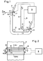
- a material web 17 possibly having holes at different points is continuously advanced in the direction of arrows F, F '.
- the web 17 is first guided around a deflection roller 19 by approximately 90 °, then runs down to a further deflection roller 22 which deflects the web 17 again by 90 ° in the opposite direction.
- the web 17 finally arrives at a deflection roller 20, around which the web 17 is guided through 180 °.
- the web then arrives at a further deflection roller 23 which deflects the web through 90 ° in a vertical direction, from where it is led upwards in the direction of arrow F 'from the arrangement.
- a laser scanner 12 and a photoelectric light receiving arrangement 11 are arranged on the deflecting roller 19.
- the laser scanner 12 generates a scanning light spot on the web resting on the deflecting roller 19, which spot periodically along a scanning line 13 in a Scans direction from edge to edge, which runs parallel to the axis of the deflection roller 19.
- the beam 24 emerging from the laser scanner 12 and displaced parallel to itself in a plane perpendicular to the plane of the drawing strikes the path 17 at a slightly different angle from the vertical, but relatively steeply in the region of the scanning line 13, so that the light receiving arrangement 11 is to be arranged at the angle of reflection to the surface of the web 17 in order to receive as much of the light reflected on the surface of the roller 19 as there is a hole 32 (FIGS. 2, 3).
- a second laser scanning device 15 of the same design is arranged above the deflection roller 20.
- a second photoelectric light receiving arrangement 14 which is designed and attached in a manner corresponding to the light receiving arrangement 11.
- the laser scanning devices 12, 15 and the light receiving arrangements 11, 14 are applied to evaluation electronics 18, which are also supplied with a feed clock signal by a feed sensor 21, so that the evaluation electronics 18 is informed about the degree of feed of the web 37 at all times.
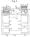
- the light receiving arrangements are designed as light guide rods 11 and 14, on one end of which a photomultiplier 25 is arranged, while the other end is provided with a mirror coating 26.
- a laser 27 optionally applies a mirror via optical means, not shown wheel 28, which deflects a reflected scanning light beam 29 to a plane mirror 30 in strip form, from which the scanning light beam is reflected back to a strip-shaped concave mirror 31, in the focal point of which the reflecting surfaces of the mirror wheel 28 are located.
- the travel beam 24, which is shifted parallel to itself, is generated, which emerges through a slot at the lower end of the housing 31 of the laser scanning device 12 or 15 and acts there on the surface of the web 17, so that the scanning along the line 13 there a laser light spot occurs.
- a hole in the track is shown at 32 in FIG. 3, for example. While the laser scanner 12 acts on the web 17 from above, the laser scanner 15 is arranged under the web 17, namely at a distance A (FIG. 1) from the laser scanner 12.
- the light guide rods 11 and 14 are shown separately in Fig. 3 only for the purpose of better detection compared to the laser scanning devices 12, 15. In fact, as in FIGS. 1 and 2, they are arranged under the reflection angle above and below the web 17.
- the distance A between the two scanning lines 13, 16 is illustrated in FIG. 1 by a line provided with arrows at the end; after installation of the device, it must be measured very precisely and stored in the evaluation electronics 18 so that the correct correlation is ensured.
- FIG. 3 shows the path on the right on the laser scanner 15 at a later point in time than on the laser scanner 12. Between the two positions shown in FIG. 3, the path 17 has traveled the distance A (FIG. 1) from the scanning line 13 to the scanning line 16.
- the evaluation electronics 18 following each light receiving arrangement 11 and 14 has a signal processing stage 33, 34 which, in addition to a signal for the current position of the mirror wheel 28 and the received signal from the photomultipliers 25, also in accordance with the dashed line Line 35 a signal representative of the feed of the web 37 is supplied.
- a threshold evaluation of the received signals and error detection take place in the signal processing stages 33.
- interfaces 36, 37 to two connected computers 38, 39 are provided, between which there is a computer interface, e.g. B. is a parallel interface.
- Suitable output devices such as printers or monitors are connected to the outputs 40, 41 of the computer 38, 39.
- the error information obtained and stored by the individual scans of the two laser scanning devices 12, 15 is correlated to total errors.
- the fault information is examined for possible holes, and the type of fault and minimum hole size are also determined.
- the holes can be output with longitudinal and transverse coordinates.
- the holes found are output via the outputs 40, 41 to suitable output devices as corresponding signals.
- the length assignment in the evaluation electronics 18 is carried out in that the individual scans of the laser scanning devices 12, 15 are synchronized in hardware with the path speed be set in order to be able to make an exact length specification (feed cycle adjustment).
- a feed clock is possible, or a signal representative of the feed is derived from the path, as is indicated by the dashed lines 35 in FIGS. 1 and 3. It is important that the inspection systems for the top and bottom are connected to the same feed clock. This means that the same cycle is always available dynamically.
- a window can be defined as a variable input parameter for the method in order to define a search area.
- the cross assignment is done in such a way that both laser scanners start scanning at the same web edge. For this purpose, both mechanical and electronic synchronization of the two mirror wheels 28 can take place.
- the counting of the transverse coordinate begins at the web edge via a hardware automatic edge. The cross assignment can therefore be carried out directly.
- a window can also be defined as a variable input parameter for the transverse coordinate in order to define a search area.
- a width threshold and an amplitude threshold can be set in the evaluation electronics 18 for the error detection during the scanning.
- the minimum hole size is a selectable parameter that can be used to define a certain minimum hole size.
- the minimum hole size to be found depends on the size of the laser light spot generated by the driving beam 24 on the scanning line 13 or 16 and on the belt speed and the scanning frequency.
- the minimum hole size that can be recognized is approximately 1.5 times the size of the light spot.
Abstract
Ein optisches Lochsuchgerät für in ihrer Längsrichtung vorgeschobene Bahnen (17) weist zwei im Abstand entlang der Bahn angeordnete Laserabtastgeräte (12, 15) auf, denen jeweils eine in Reflexion arbeitende Lichtempfangsanordnung (11, 14) zugeordnet ist. Die beiden Lichtempfangsanordungen (11, 14) sind an eine Auswerteelektronik (18) angeschlossen, in deren die beiden an gleichen Stellen der Bahn (17) erfaßten photo elektrischen Empfangssignale korreliert und daraufhin untersucht werden, ob sie gleich sind oder nicht.An optical hole locator for webs (17) advanced in their longitudinal direction has two laser scanning devices (12, 15) arranged at a distance along the web, each of which is assigned a light-receiving arrangement (11, 14) operating in reflection. The two light receiving arrangements (11, 14) are connected to evaluation electronics (18), in which the two photoelectric reception signals detected at the same points on the web (17) are correlated and then examined whether they are the same or not.
Description
Die Erfindung betrifft ein optisches Lochsuchgerät für in ihrer Längsrichtung vorgeschobene Bahnen mit einem Laserabtastgerät, welches einen Fahrstrahl auf die Oberfläche der Bahn richtet, der die Bahn quer zu Ihrer Längsrichtung entlang einer Abtastlinie abtastet, und mit einer parallel zur Abtastlinie angeordneten, linearen photoelektrischen Lichtempfangsanordnung, die von Löchern in der Bahn beeinflusstes Licht von der Abtastlinie empfängt und an einer Auswerteelektronik ein elektrisches Signal abgibt, welches von der Auswerteelektronik auf eine für Löcher in der Bahn charakteristische Form und Große ausgewertet wird.The invention relates to an optical hole locator for webs advanced in their longitudinal direction with a laser scanning device, which directs a beam onto the surface of the web, which scans the web transverse to its longitudinal direction along a scanning line, and with a linear photoelectric light receiving arrangement arranged parallel to the scanning line. which receives light influenced by holes in the path from the scanning line and emits an electrical signal to an evaluation electronics, which is evaluated by the evaluation electronics to a shape and size characteristic of holes in the path.
Mit Laser-Abtastgeräten und linearen Lichtempfangsvorrichtungen arbeitende Oberflächeninspektionsvorrichtungen zur Erkennung dunkler Flecken aller Art und in jeder Größe sind in verschiedenen Ausführungen bekannt (z. B. DE-OS 28 57 076, DE-OS 28 27 705).Various types of surface inspection devices for detecting dark spots of all types and in any size are known which use laser scanning devices and linear light receiving devices (e.g. DE-OS 28 57 076, DE-OS 28 27 705).
Derartige optische Oberflächeninspektionsgeräte gestatten zwar grundsätzlich auch die Locherkennung; es ist jedoch problematisch, bestimmte Arten von Flecken oder sonstigen Oberflächen von Löchern zu unterscheiden.Such optical surface inspection devices basically also allow hole detection; however, it is difficult to distinguish certain types of stains or other surfaces from holes.
Aus diesem Grunde wurden bisher zur Lochsuche in erster Linie in Tranmission arbeitende Lochsuchgeräte verwendet (DE-OS 28 08 359, DE-OS 29 34 554); diese Geräte gestatten zwar eine sicher Locherkennung, weil nur bei Löchern das Licht durch die Bahn zur Lichtempfangsanordnung hindurchgeht, doch erfordern diese bekannten Lochsuchgeräte ein Lichtsendegerät auf einer Seite der Bahn und eine Lichtempfangsanordnung auf der entgegengesetzten Seite der Bahn. Dies macht eine Lochinspektion an solchen Stellen der laufenden Bahn unmöglich, die über eine Umlenkwalze geführt sind. Die Lochsuche auf optischen Wege kann also hier nur vor oder hinter der Umlenkwalzen vorgenommen werden, wo die Bahn je doch insbesondere bei höheren Geschwindigkeiten flattert und somit ein unsicheres Lochmeldesignal zu erwarten ist.For this reason, hole locators that have been used primarily in transmission to locate holes (DE-OS 28 08 359, DE-OS 29 34 554); although these devices permit reliable hole detection because the light only passes through the web to the light receiving arrangement in the case of holes, these known hole locators require a light emitting device on one side of the web and a light receiving arrangement on the opposite side of the web. This makes hole inspection impossible at those points on the running web that are guided over a deflection roller. The hole search optically can only be done here in front of or behind the deflection rollers, where the web ever but flutters especially at higher speeds and therefore an unsafe punch signal is to be expected.
Ein weiteres Problem stellt der relativ unscharfe Lichtfleck dar. Wird ein derartiges Lochsuchgerät zusätzlich zu einem Oberflächeinspektionsgerät installiert, treten bauliche Schwierigkeiten auf.Another problem is the relatively unsharp light spot. If such a hole locating device is installed in addition to a surface inspection device, structural difficulties arise.
Das Ziel der vorliegenden Erfindung besteht darin, ein optisches Lochsuchgerät mit sicherer Locherkennung zu schaffen, bei dem auch in Bereichen, wo die vorgeschobene Bahn über nicht lichtdurchlässige Umlenkwalzen geführt wird, eine optische Lochsuche erfolgen kann.The aim of the present invention is to provide an optical hole finder with reliable hole detection, in which an optical hole search can also be carried out in areas where the advanced web is guided over non-transparent deflection rollers.
Zur Lösung dieser Aufgabe sieht die Erfindung vor, daß die photoelektrische Lichtempfangsanordnung auf der gleichen Seite wie das Laserabtastgerät angeordnet ist und von der Abtastlinie reflektiertes Licht empfängt, das in einem definierten Abstand in Richtung des Vorschubs der Bahn von dem ersten Laserabtastgerät ein zweites Abtastgerät auf der entgegengesetzten Seite der Bahn angeordnet ist, welches in dem definierten Abstand A die andere Seite der Bahn mit einem Fahrstrahl entlang einer zur ersten parallelen zweiten Abtastlinie abtastet, daß sich auf der gleichen Seite der Bahn wie das zweite Laserabtastgerät parallel zur zweiten Abtastlinie eine weitere lineare photoelektrische Lichtempfangsanordnung erstreckt, die von der zweiten Abtastlinie reflektiertes Licht empfängt und ein elektrisches Signal an die Auswerteelektronik abgibt, und daß die von beiden photoelektrischen Lichtempfangsanordnungen an die Auswerteelektronik abgegebene elektrischen Signale durch Zwischenspeicherung der zuerst empfangenen Signale in Korrelation gebracht werden und daß ein Lochsignal abgegeben wird, wenn beide Lichtempfangsanordnungen an der gleichen Stelle der Bahn das gleiche Signal abgeben.To achieve this object, the invention provides that the photoelectric light receiving arrangement is arranged on the same side as the laser scanner and receives light reflected from the scanning line, which at a defined distance in the direction of the advance of the web from the first laser scanner on the second scanner opposite side of the path is arranged, which at the defined distance A scans the other side of the path with a travel beam along a second scanning line parallel to the first, that on the same side of the path as the second laser scanner parallel to the second scanning line, another linear photoelectric Light receiving arrangement extends, which receives light reflected from the second scanning line and emits an electrical signal to the evaluation electronics, and that the electrical signals emitted by both photoelectric light reception arrangements to the evaluation electronics by intermediate storage de r signals received first are correlated and that a hole signal is emitted if both light receiving arrangements emit the same signal at the same point on the path.
Der Grundgedanke der vorliegenden Erfindung ist also darin zu erblicken, daß die laufende Bahn durch zwei gesonderte Laserabtastgeräte bzw. photoelektrische Lichtempfangsanordnungen von beiden Seiten an in Längsrichtung einen Abstand aufweisenden Stellen abgetastet wird und daß die bei diesen beiden Abtastungen gewonnen Empfangssignale in der Weise miteinander korreliert werden, daß in jedem Augenblick zwei Empfangssignale elektronische verglichen werden, die bei der zu verschiedenen Zeiten erfolgten Abtastung der gleichen Stelle der Bahn gewonnen wurden.The basic idea of the present invention is therefore to be seen in that the running web is scanned by two separate laser scanners or photoelectric light receiving arrangements from both sides at locations that are spaced in the longitudinal direction and that the received signals obtained in these two scans are correlated with one another in this way that at any moment two received signals are compared electronically, which were obtained by scanning the same point on the path at different times.
Da Flecken aufgrund der statistischen Verteilung auf beiden Seiten der Bahn im allgemeinen nicht zusammenfallen, werden die von Flecken oder sonstigen Strukturen auf entgegengesetzten Oberflächen der Bahn herrührenden Empfangssignale grundsätzlich verschieden ausfallen. Von Löchern in der Bahn herrührende Signale sind jedoch praktisch gleich, unabhängig davon, von welcher Seite das Loch durch ein Laserabtastgerät und die zugeordnete Lichtempfangsanordnung erfaßt wurde. Werden also durch die elektronische Korrelationsvorrichtung an der gleichen Stelle der Bahn zwei gleiche Fehlersignale erkannt, so ist dies im allgemeinen ein sicheres Anzeichen für das Vorliegen eines Loches.Since spots generally do not coincide on both sides of the web due to the statistical distribution, the received signals from spots or other structures on opposite surfaces of the web will be fundamentally different. However, signals originating from holes in the web are practically the same regardless of the side from which the hole was detected by a laser scanner and the associated light receiving arrangement. If two identical error signals are thus recognized by the electronic correlation device at the same point on the path, this is generally a sure sign of the presence of a hole.
Erfindungsgemäß sind die beiden Laserabtastgeräte und Lichtempfangsanordnungen exakt gleich ausgebildet und auch im gleichen Abstand und unter gleicher Winkeln zur Oberfläche der Bahn angeordnet.According to the invention, the two laser scanning devices and light receiving arrangements are of exactly the same design and are also arranged at the same distance and at the same angles to the surface of the web.
Besonders vorteilhaft ist es, daß die Bahn am Ort der Laserabtastgerät und der Lichtempfangsanordnungen um drehende Umlenkwalzen in der einen bzw. anderen Richtung herumgeführt sind.It is particularly advantageous that the web is guided around rotating deflecting rollers in one or the other direction at the location of the laser scanning device and the light receiving arrangements.
Auf diese Weise kann das von den Oberflächen der Walze ref lektierte Licht in besonders vorteilhafter und effektiver Weise für die Auslösung eines Lochsignals herangezogen werden. Die Lochsuche erfolgt in diesem Fall auch an einer Stelle der Bahn, wo diese aufgrund der Führung auf Walzen besonders ruhig und flatterfrei geführt ist.In this way, the surface of the roller ref selected light can be used in a particularly advantageous and effective manner for triggering a hole signal. In this case, the hole search is also carried out at a point on the web where it is guided particularly smoothly and flutter-free due to the guidance on rollers.
Weitere vorteilhafte Ausgestaltungen der Erfindung sind durch die Patentansprüche 3 bis 12 gekennzeichnet.Further advantageous embodiments of the invention are characterized by claims 3 to 12.
Die Vorteile der Erfindung bestehen darin, daß aufgrund der beiderseitigen Inspektion kein Transmissionsempfänger nachgerüstet werden muß. Es kann direkt auf der Walze inspiziert werden. Einbauprobleme entfallen. Durch den möglichen Verzicht auf einen Transmissionsempfänger ist ein kostengünstiger auch nachträglicher Einbau bei bestehenden Bahnführungsanlagen möglich.The advantages of the invention are that no transmission receiver has to be retrofitted due to the mutual inspection. It can be inspected directly on the roller. Installation problems are eliminated. Because there is no need for a transmission receiver, it can also be retrofitted to existing web guiding systems at low cost.
Beim nachträglichen Einbau eines erfindungsgmäßen Lochsuchgeräts in bestehende Anlagen mit vorgeschobenen Bahnen können die beiden Laserabtastgeräte mit zugeordneter Lichtempfangsanordung an beliebigen bereits vorhandenen Umlenkwalzen angeordnet werden, wo gerade ausreichend Platz zur Verfügung steht. Der Abstand der beiden Geräte in Vorschubrichtung der Bahn kann in der Elektronik durch geeignete Korrelation berücksichtigt werden. Er muß lediglich ein einziges Mal nach Installation der Laserabtastgeräte mit den Lichtempfangsvorrichtungen exakt ausgemessen, festgestellt und in die Auswerteelektronik fest eingegeben werden.When a hole finder according to the invention is retrofitted into existing systems with advanced tracks, the two laser scanning devices with associated light receiving arrangement can be arranged on any existing deflection rollers where there is just enough space available. The distance between the two devices in the feed direction of the web can be taken into account in the electronics by means of a suitable correlation. It only has to be measured once, exactly once, after installing the laser scanning devices with the light receiving devices, ascertained and firmly entered into the evaluation electronics.
Auch Beulen und Eindrücke in der Oberfläche der Bahn stören die Lochsuch- und -messung nicht, da diese Fehler zwar gleichzeitig auf beiden Seiten der Bahn auftreten. Sie liefern jedoch ein von Löchern so abweichendes Fehlerbild, daß eine Unterscheidung in der Elektronik problemlos möglich ist.Dents and impressions in the surface of the web do not interfere with hole search and measurement, since these errors occur simultaneously on both sides of the web. However, they provide an error pattern that deviates from holes so that a distinction in the electronics is possible without any problems.
Die Erfindung wird im folgenden beispielsweise anhand der Zeichnung beschrieben; in dieser zeigt
- Fig. 1 eine schematische Seitenansicht eines erfindungsgemäßen optischen Lochsuchgerätes in Anordung an einer um mehrere Umlenkwalzen geführten laufenden Bahn,
- Fig. 2 eine Draufsicht auf die Bahn im Bereich einer
Abtastlinie 13 bzw. 16 und - Fig. 3 eine schematische Darstellung der beiden beim erfindungsgemäßen optischen Lochsuchgerät verwendeten Laserabtastgeräte und zugeordneten Lichtempfangsanordnungen mit der angeschlossenen Auswerteelektronik.
- 1 is a schematic side view of an optical hole finder according to the invention arranged on a running web guided around a plurality of deflection rollers,
- Fig. 2 is a plan view of the path in the region of a
scan line - Fig. 3 is a schematic representation of the two laser scanning devices used in the optical hole finder according to the invention and associated light receiving arrangements with the connected evaluation electronics.
Nach Fig. 1 wird eine möglicherweise an verschiedenen Stellen Löcher aufweisende Materialbahn 17 in Richtung der Pfeile F, F′ kontinuierlich vorgeschoben. Die Bahn 17 wir zunächst um eine Umlenkwalze 19 um etwa 90° herumgeführt, verläuft dann abwärts bis zu einer weiteren Umlenkwalze 22, die die Bahn 17 erneut um 90° in der entgegengesetzten Richtung umlenkt. Die Bahn 17 gelangt schließlich zu einer Umlenkwalze 20, um die die Bahn 17 um 180° herumgeführt ist. Anschließend gelangt die Bahn auf eine weitere Umlenkwalze 23 die die Bahn um 90° in eine vertikale Richtung umlenkt, von wo aus sie nach oben in Richtung des Pfeiles F′ aus der Anordung herausgeführt wird.According to FIG. 1, a
Nach Fig. 1 und 2 ist an der Umlenkwalze 19 ein Laserabtastgerät 12 und eine photoelektrische Lichtempfangsanordung 11 angeordent. Das Laserabtastgerät 12 erzeugt auf der auf der Umlenkwalze 19 aufliegenden Bahn einen Abtastlichtfleck, der die Bahn entlang einer Abtastlinie 13 periodisch in einer Richtung von Kante zu Kante abtastet, welche parallel zur Achse der Umlenkwalze 19 verläuft. Der aus dem Laserabtastgerät 12 austretende, in einer senkrecht auf der Zeichnungsebene stehenden Ebene parallel zu sich selbst verschobene Fahrstrahl 24 trifft unter einem von der Senkrechten etwas abweichenden Winkel, jedoch relativ steil im Bereich der Abtastlinie 13 auf die Bahn 17 auf, so daß die Lichtempfangsanordnung 11 unter dem Reflexionswinkel zur Oberfläche der Bahn 17 anzuordnen ist, um möglichst viel von dem im Falle des Vorliegens eines Loches 32 (Fig. 2, 3) an der Oberfläche der Walze 19 reflektierten Lichtes zu empfangen.1 and 2, a
In entsprechender Weise ist ein gleich ausgebildetes zweites Laserabtastgerät 15 über der Umlenkwalze 20 angeordnet. Unter dem Reflexionswinkel befindet sich dort weiter eine zweite photoelektrische Lichtempfangsanordnung 14, die in entsprechender Weise wie die Lichtempfangsanordnung 11 ausgebildet und angebracht ist.In a corresponding manner, a second
Die Laserabtastgeräte 12, 15 und die Lichtempfangsanordungen 11, 14 sind an eine Auswerteelektronik 18 angelegt, der auch von einem Vorschubfühler 21 ein Vorschubtaktsignal zugeführt wird, damit die Auswerteelektronik 18 in jedem Augenblick über den Grad des Vorschubs der Bahn 37 informiert ist.The
Die Lichtempfangsanordungen sind beim Ausführungsbeispiel nach Fig. 1 und 2 als Lichtleitstäbe 11 bzw. 14 ausgebildet, an deren einer Stirnseite ein Photomultiplier 25 angeordnet ist, während die andere Stirnseite mit einer Verspiegelung 26 versehen ist.In the exemplary embodiment according to FIGS. 1 and 2, the light receiving arrangements are designed as
Der Aufbau der Laserabtastgeräte 12, 15 ergibt sich in schematischer Weise aus Fig. 3. Ein Laser 27 beaufschlagt gegebenenfalls über nicht dargestellte optische Mittel ein Spiegel rad 28, welches einen reflektierten Abtastlichtstrahl 29 zu einem Planspiegel 30 in Streifenform umlenkt, von dem das Abtastlichtbündel zu einem streifenförmigen Hohlspiegel 31 zurückreflektiert wird, in dessen Brennpunkt sich die reflektierenden Oberflächen des Spiegelrades 28 befinden. Auf diese Weise wird der parallel zu sich selbst verschobene Fahrstrahl 24 erzeugt, der durch einen Schlitz am unteren Ende des Gehäuses 31 des Laserabtastgerätes 12 bzw. 15 austritt und dort die Oberfläche der Bahn 17 beaufschlagt, so daß dort entlang der Linie 13 die Abtastung mit einem Laserlichtfleck erfolgt. Ein Loch in der Bahn ist beispielsweise bei 32 in Fig. 3 wiedergegeben. Während das Laserabtastgerät 12 die Bahn 17 von oben beaufschlagt, ist das Laserabtastgerät 15 unter der Bahn 17 angeordnet, und zwar im Abstand A (Fig. 1) vom Laserabtastgerät 12.The structure of the
Die Lichtleitstäbe 11 bzw. 14 sind nur zum Zwecke der besseren Erkennung gegenüber den Laserabtastgeräten 12, 15 in Fig. 3 seitlich gesondert dargestellt. Tatsächlich sind sie wie nach den Fig. 1 und 2 unter dem Reflexionswinkel oberhalb bzw. unterhalb der Bahn 17 angeordnet.The
Der Abstand A zwischen den beiden Abtastlinien 13, 16 ist in Fig. 1 durch eine mit Pfeilen am Ende versehene Linien veranschaulicht; er muß nach Installation der Vorrichtung sehr genau ausgemessen und in der Auswerteelektronik 18 gespeichert werden, damit die richtige Korrelation gewährleistet ist.The distance A between the two
In Fig. 3 ist Bahn rechts an dem Laserabtastgerät 15 zu einem späteren Zeitpunkt als am Laserabtastgerät 12 dargestellt. Zwischen den beiden in Fig. 3 dargestellten Positionen hat die Bahn 17 den Abstand A (Fig. 1) von der Abtastlinie 13 zur Abtastlinie 16 durchlaufen.3 shows the path on the right on the
Aus Fig. 3 ergibt sich auch, daß die Auswerteelektronik 18 im Anschluß an jede Lichtempfangsanordung 11 bzw. 14 eine Signalverarbeitungsstufe 33, 34 aufweist, der außer einem Signal für die momentane Stellung des Spiegelrades 28 und dem Empfangssignal von den Photomultipliern 25 auch gemäß der gestrichelten Linie 35 ein für den Vorschub der Bahn 37 repräsentatives Signal zugeführt ist.From Fig. 3 it also follows that the
In den Signalverarbeitungsstufen 33 findet eine Schwellenauswertung der empfangenen Signale und eine Fehlerdedektion statt.A threshold evaluation of the received signals and error detection take place in the
Am Ausgang der Signalverarbeitungsstufen 33, 34 sind Schnittstellen 36, 37 zu zwei angeschlossenen Rechnern 38, 39 vorgesehen, zwischen denen sich eine Rechnerschnittstelle, z. B. ein Parallelinterface befindet.At the output of the
An die Ausgänge 40, 41 der Rechner 38, 39 sind geeignete Ausgabegeräte wie Drucker oder Monitore angeschlossen.Suitable output devices such as printers or monitors are connected to the
In den Rechnern erfolgt eine Korrelation der durch die einzelnen Abtastungen der beiden Laserabtastgeräte 12, 15 erhaltenen und abgespeicherten Fehlerinformation zu Gesamtfehlern. Die Fehlerinformation wird auf mögliche Löcher untersucht, wobei außerdem Fehlerart und Mindestlochgröße festgestellt werden. Es erfolgt außerdem ein Austausch möglicher Lochfehlerinformationen zwischen den Rechern 38, 39. Die Löcher können mit Längs- und Querkoordinaten ausgegeben werden. Die gefunden Löcher werden über die Ausgänge 40, 41 an geeignete Ausgabegeräte als entsprechende Signale abgegeben.In the computers, the error information obtained and stored by the individual scans of the two
Die Längenzuordung in der Auswerteelektronik 18 erfolgt dadurch, daß die einzelenen Abtastungen der Laserabtastgeräte 12, 15 hardwaremäßig auf die Bahngeschwindigkeit synchroni siert werden, um eine genaue Längenangabe machen zu können (Vorschubtaktanpassung). Dazu ist ein Vorschubtaktgeber möglich, oder es wird ein für den Vorschub repräsentatives Signal von der Bahn abgeleitet, wie das durch die gestrichelten Linien 35 in den Fig. 1 und 3 angedeutet ist. Wichtig ist, daß die Inspektionssysteme für Oberseite und Unterseite am gleichen Vorschubtaktgeber hängen. Damit ist dynamisch immer der gleiche Takt vorhanden.The length assignment in the
Mit der ausgemessenen Längendifferenz und der Tatsache, daß ein Vorschubtaktgeber verwendet wird, kann die Längenzuordnung sehr genau realisiert werden. Für das Verfahren kann ein Fenster als variabler Eingabeparamter definiert werden, um einen Suchbereich festzulegen.With the measured length difference and the fact that a feed clock is used, the length assignment can be realized very precisely. A window can be defined as a variable input parameter for the method in order to define a search area.
Die Querzuordnung erfolgt in der Weise, daß beide Laserabtastgeräte bei derselben Bahnkante mit der Abtastung beginnen. Hierzu kann sowohl eine mechanische als auch elektronische Synchronisation der beiden Spiegelräder 28 erfolgen. Über eine hardwaremäßige Kantenautomatik beginnt die Zählung der Querkoordinate bei der Bahnkante. Die Querzuordnung kann deshalb direkt ausgeführt werden.The cross assignment is done in such a way that both laser scanners start scanning at the same web edge. For this purpose, both mechanical and electronic synchronization of the two
Auch bei der Querkoordinate kann ein Fenster als variabler Eingabeparameter definiert werden, um einen Suchbereich festzulegen.A window can also be defined as a variable input parameter for the transverse coordinate in order to define a search area.
Um ein gesichertes Erkennen von Löchern noch besser abstimmen zu können, können in der Auswerteelektronik 18 für die Fehlererkennung bei der Abtastung eine Breitenschwelle und eine Amplitudenschwelle festgesetzt werden.In order to be able to tune a reliable detection of holes even better, a width threshold and an amplitude threshold can be set in the
Die Mindestlochgröße ist ein eingebbarer wählbarer Parameter, über den eine bestimmte minimale Lochgröße festgelegt werden kann.The minimum hole size is a selectable parameter that can be used to define a certain minimum hole size.
Die vorgenannten vier Kriterien müssen erfüllt werden, damit ein Loch als solches erkannt wird.The above four criteria must be met for a hole to be recognized as such.
Die zu findende minimale Lochgröße hängt von der Größe des vom Fahrstrahl 24 erzeugten Laserlichtflecks auf der Abtastlinie 13 bzw. 16 und von der Bandgeschwindigkeit und der Abtastfrequenz ab. Die minimale Lochgröße, die erkannt werden kann, liegt bei ca. dem 1,5-fachen der Lichtfleckgröße.The minimum hole size to be found depends on the size of the laser light spot generated by the
Claims (10)
daß die photoelektrische Lichtempfangsanordnung (11) auf der gleichen Seite wie das Laserabtastgerät (12) angeordnet ist und von der Abtastlinie (13) reflektiertes Licht empfängt, das in einem definierten Abstand (A) in Richtung des Vorschubs der Bahn von dem ersten Laserabtastgerät (12) ein zweites Laserabtastgerät (14) auf der entgegengesetzten Seite der Bahn (17) angeordnet ist, welches in dem definierten Abstand (A) die andere Seite der Bahn (17) mit einem Fahrstrahl entlang einer zur ersten (13) parallelen zweiten Abtastlinie (16) abtastet, daß sich auf der gleichen Seite der Bahn (17) wie das zweite Laserabtastgerät (15) parallel zur zweiten Abtastlinie (16) eine weitere lineare photoelektrische Lichtempfangsanordnung (14) erstreckt, die von der zweiten Abtastlinie (16) reflektiertes Licht empfängt und ein elektrisches Signal aus die Auswerteelektronik (18) abgibt, und daß die von beiden photoelektrischen Lichtempfangsanordnungen (11, 14) an die Auswerteelektronik (18) abgegebene elektrischen Signale durch Zwischenspeicherung der zuerst empfangenen Signale in Korrelation gebracht werden und daß ein Lochsignal abgegeben wird, wenn beide Lichtempfangsanordnungen (11, 14) an der gleichen Stelle der Bahn (17) im wesentlichen das gleiche Signal abgeben.1.Optical hole finder for webs advanced in the longitudinal direction with a laser scanner, which directs a beam onto the surface of the web, which scans the web transverse to its longitudinal direction along a scanning line, and with a linear photoelectric light receiving arrangement arranged parallel to the scanning line, which by Receives light influenced by holes in the web from the scanning line and emits an electrical signal to evaluation electronics, which is evaluated by the evaluation electronics for a shape and size characteristic of holes in the web, characterized in that
that the photoelectric light receiving arrangement (11) is arranged on the same side as the laser scanner (12) and receives light reflected from the scan line (13) which is at a defined distance (A) in the direction of advancement of the web from the first laser scanner (12 ) a second laser scanner (14) is arranged on the opposite side of the web (17), which at the defined distance (A) the other side of the web (17) with a driving beam along a second scanning line (16 ) scans that on the same side of the web (17) as the second laser scanning device (15) parallel to the second scanning line (16) there is another linear photoelectric Extends light receiving arrangement (14) which receives light reflected by the second scanning line (16) and emits an electrical signal from the evaluation electronics (18), and that the electrical signals emitted by both photoelectric light receiving arrangements (11, 14) to the evaluation electronics (18) can be correlated by temporarily storing the signals received first and that a hole signal is emitted if both light receiving arrangements (11, 14) emit essentially the same signal at the same point on the path (17).
dadurch gekennzeichnet, daß die Bahn (17) am Ort der Laserabtastgeräte (12, 15) und der Lichtempfangsanordnungen (11, 14) um drehende Umlenkwalzen (19, 20) in der einen bzw. anderen Richtung herumgeführt sind, wobei insbesondere die Oberflächen der Umlenkwalzen (19, 20) einen guten Kontrast zur Bahn (17) haben und zweckmäßig bei glänzender Bahn (17) dunkel bzw. matt und bei nichtglänzender Bahn (17) hell bzw. glänzend sind.2. hole finder according to claim 1,
characterized in that the web (17) at the location of the laser scanning devices (12, 15) and the light receiving arrangements (11, 14) are guided around rotating deflecting rollers (19, 20) in one or the other direction, in particular the surfaces of the deflecting rollers (19, 20) have a good contrast to the web (17) and are expediently dark or matt with a glossy web (17) and light or glossy with a non-glossy web (17).
Applications Claiming Priority (2)
| Application Number | Priority Date | Filing Date | Title |
|---|---|---|---|
| DE3739436A DE3739436C1 (en) | 1987-11-20 | 1987-11-20 | Optical hole finder |
| DE3739436 | 1987-11-20 |
Publications (3)
| Publication Number | Publication Date |
|---|---|
| EP0316746A2 true EP0316746A2 (en) | 1989-05-24 |
| EP0316746A3 EP0316746A3 (en) | 1990-06-06 |
| EP0316746B1 EP0316746B1 (en) | 1993-08-04 |
Family
ID=6340933
Family Applications (1)
| Application Number | Title | Priority Date | Filing Date |
|---|---|---|---|
| EP88118660A Expired - Lifetime EP0316746B1 (en) | 1987-11-20 | 1988-11-09 | Optical apparatus for the detection of holes |
Country Status (6)
| Country | Link |
|---|---|
| US (1) | US5095214A (en) |
| EP (1) | EP0316746B1 (en) |
| JP (1) | JPH01162138A (en) |
| KR (1) | KR920003534B1 (en) |
| AU (1) | AU607280B2 (en) |
| DE (2) | DE3739436C1 (en) |
Cited By (4)
| Publication number | Priority date | Publication date | Assignee | Title |
|---|---|---|---|---|
| EP0475454A3 (en) * | 1990-09-14 | 1992-10-14 | Fuji Photo Film Co., Ltd. | Defect inspection system |
| EP0668499A2 (en) * | 1994-02-16 | 1995-08-23 | Cmd Corporation | Apparatus and method for detecting a formation in a sheet material |
| US5861078A (en) * | 1993-08-12 | 1999-01-19 | Cmd Corporation | Method and apparatus for detecting a seal on a plastic bag |
| EP0936459A1 (en) * | 1998-02-13 | 1999-08-18 | Bähr GmbH Bremen - Industrie Technik | Method and apparatus for testing the layer adhesion of multilayer foil-web |
Families Citing this family (20)
| Publication number | Priority date | Publication date | Assignee | Title |
|---|---|---|---|---|
| US5383135A (en) * | 1992-12-31 | 1995-01-17 | Zellweger Uster, Inc. | Acquisition, measurement and control of thin webs on in-process textile materials |
| DE19506456C2 (en) * | 1995-02-24 | 1999-07-01 | Boewe Systec Ag | Control device for monitoring the running of two superimposed paper webs in a paper processing machine |
| US5644141A (en) * | 1995-10-12 | 1997-07-01 | The United States Of America As Represented By The Administrator Of The National Aeronautics And Space Administration | Apparatus and method for high-speed characterization of surfaces |
| US5994712A (en) * | 1997-07-29 | 1999-11-30 | Mack; John Edward | Belt flaw detector |
| US6895811B2 (en) * | 2001-12-14 | 2005-05-24 | Shawmut Corporation | Detection of small holes in laminates |
| DE20120977U1 (en) * | 2001-12-27 | 2003-04-30 | Bat Cigarettenfab Gmbh | Cutting control for an inner wrapper for a cigarette group |
| DE10204939A1 (en) * | 2002-02-07 | 2003-09-04 | Parsytec Comp Gmbh | Device for generating flat parallel light has two adjacent lenses in plane perpendicular to main radiation direction, illuminated in 2-D by one of two point sources, parallel in at least one dimension |
| US8210791B2 (en) * | 2004-05-03 | 2012-07-03 | Jervis B. Webb Company | Automatic transport loading system and method |
| US7980808B2 (en) * | 2004-05-03 | 2011-07-19 | Jervis B. Webb Company | Automatic transport loading system and method |
| US8075243B2 (en) | 2004-05-03 | 2011-12-13 | Jervis B. Webb Company | Automatic transport loading system and method |
| US8192137B2 (en) | 2004-05-03 | 2012-06-05 | Jervis B. Webb Company | Automatic transport loading system and method |
| CN101090840A (en) * | 2004-05-03 | 2007-12-19 | 杰维斯·B·韦布国际公司 | Automatic transport loading system and method |
| JP4456426B2 (en) * | 2004-07-06 | 2010-04-28 | 富士フイルム株式会社 | Detection device |
| US20060276958A1 (en) * | 2005-06-02 | 2006-12-07 | Jervis B. Webb Company | Inertial navigational guidance system for a driverless vehicle utilizing laser obstacle sensors |
| WO2010039135A1 (en) * | 2008-10-01 | 2010-04-08 | Hewlett-Packard Development Company, L.P. | Camera web support |
| DE202013102069U1 (en) * | 2013-05-13 | 2014-08-14 | Eltromat Gmbh | Color measuring device, in particular for printing machines |
| KR101567708B1 (en) | 2014-07-09 | 2015-11-10 | 현대자동차주식회사 | Method and apparatus for detecting the defect of a fuel cell membrane-electrode assembly |
| KR101741224B1 (en) * | 2015-05-08 | 2017-05-30 | 주식회사 한성시스코 | textile cord counting apparatus for tire jointless reinforced belt |
| CN104949992A (en) * | 2015-05-19 | 2015-09-30 | 东莞市威力固电路板设备有限公司 | Printed circuit board (PCB) automated optical inspection (AOI) system and PCB objective table suitable for same |
| CN108788893B (en) * | 2018-07-20 | 2023-12-05 | 中铁武汉电气化局集团第一工程有限公司 | Hole device is sought to flat cantilever mounting hole |
Citations (5)
| Publication number | Priority date | Publication date | Assignee | Title |
|---|---|---|---|---|
| US3786265A (en) * | 1973-02-02 | 1974-01-15 | Lindly Company Inc | Apparatus for detecting defects in continuous traveling material |
| US4310250A (en) * | 1980-02-01 | 1982-01-12 | Erwin Sick Gmbh | Apparatus for monitoring for faults in translucent strip material |
| JPS61175552A (en) * | 1985-01-30 | 1986-08-07 | Kanzaki Paper Mfg Co Ltd | Detection of defective sheet |
| DE3544871A1 (en) * | 1984-12-19 | 1986-09-11 | Erwin Sick Gmbh Optik-Elektronik, 7808 Waldkirch | Optical fault-finding device |
| JPS61217747A (en) * | 1985-03-23 | 1986-09-27 | Yodogawa Seikosho:Kk | Pinhole detector |
Family Cites Families (18)
| Publication number | Priority date | Publication date | Assignee | Title |
|---|---|---|---|---|
| NL106466C (en) * | 1954-12-16 | |||
| DE1235034B (en) * | 1959-02-26 | 1967-02-23 | Licentia Gmbh | Electrical evaluation circuit for a surface scanning device |
| DE1297892B (en) * | 1963-04-23 | 1969-06-19 | Lippke Paul | Device for electro-optical testing of moving webs or sheets |
| CH543088A (en) * | 1970-09-23 | 1973-10-15 | Ciba Geigy Ag | Device for the continuous inspection of a photographic film for cracks |
| FR2126370B1 (en) * | 1971-02-24 | 1973-06-29 | Columbia Research Corp | |
| DE2808359C3 (en) * | 1978-02-27 | 1980-09-04 | Erwin Sick Gmbh Optik-Elektronik, 7808 Waldkirch | Finding device for holes in lanes |
| DE2827705C3 (en) * | 1978-06-23 | 1981-07-30 | Erwin Sick Gmbh Optik-Elektronik, 7808 Waldkirch | Device for the detection of defects in web material |
| DE2904433C2 (en) * | 1979-02-06 | 1984-05-17 | Erwin Sick Gmbh Optik-Elektronik, 7808 Waldkirch | Film defect monitoring device |
| DE2934554C2 (en) * | 1979-08-27 | 1984-08-02 | Erwin Sick Gmbh Optik-Elektronik, 7808 Waldkirch | Optoelectronic monitoring device. |
| DE2947791C2 (en) * | 1979-11-28 | 1985-04-18 | Licentia Patent-Verwaltungs-Gmbh, 6000 Frankfurt | Device for color monitoring of sheet-like or web-shaped materials in motion, in particular the printing materials of printing machines |
| DE3013549C2 (en) * | 1980-04-09 | 1984-06-14 | Erwin Sick Gmbh Optik-Elektronik, 7808 Waldkirch | Arrangement for signal evaluation in a hole detection device |
| US4389575A (en) * | 1980-07-03 | 1983-06-21 | Sparton Corporation | Fabric inspection system |
| GB2081891A (en) * | 1980-08-11 | 1982-02-24 | Wiggins Teape The Group Ltd | Web monitoring apparatus |
| JPS6333160Y2 (en) * | 1980-09-27 | 1988-09-05 | ||
| CH656466A5 (en) * | 1982-02-15 | 1986-06-30 | Alusuisse | METHOD AND DEVICE FOR THE SURFACE CONTROL OF A MATERIAL. |
| KR890002004B1 (en) * | 1984-01-11 | 1989-06-07 | 가부시끼 가이샤 도오시바 | Distinction apparatus of papers |
| GB8501910D0 (en) * | 1985-01-25 | 1985-02-27 | Haigh Chadwick Ltd | Web monitoring arrangement |
| US4728800A (en) * | 1985-04-24 | 1988-03-01 | Young Engineering, Inc. | Apparatus and method for detecting defects in a moving web |
-
1987
- 1987-11-20 DE DE3739436A patent/DE3739436C1/en not_active Expired
-
1988
- 1988-11-09 DE DE8888118660T patent/DE3882915D1/en not_active Expired - Fee Related
- 1988-11-09 EP EP88118660A patent/EP0316746B1/en not_active Expired - Lifetime
- 1988-11-15 AU AU25142/88A patent/AU607280B2/en not_active Ceased
- 1988-11-16 US US07/272,195 patent/US5095214A/en not_active Expired - Fee Related
- 1988-11-19 KR KR1019880015245A patent/KR920003534B1/en not_active IP Right Cessation
- 1988-11-21 JP JP63294476A patent/JPH01162138A/en active Pending
Patent Citations (5)
| Publication number | Priority date | Publication date | Assignee | Title |
|---|---|---|---|---|
| US3786265A (en) * | 1973-02-02 | 1974-01-15 | Lindly Company Inc | Apparatus for detecting defects in continuous traveling material |
| US4310250A (en) * | 1980-02-01 | 1982-01-12 | Erwin Sick Gmbh | Apparatus for monitoring for faults in translucent strip material |
| DE3544871A1 (en) * | 1984-12-19 | 1986-09-11 | Erwin Sick Gmbh Optik-Elektronik, 7808 Waldkirch | Optical fault-finding device |
| JPS61175552A (en) * | 1985-01-30 | 1986-08-07 | Kanzaki Paper Mfg Co Ltd | Detection of defective sheet |
| JPS61217747A (en) * | 1985-03-23 | 1986-09-27 | Yodogawa Seikosho:Kk | Pinhole detector |
Non-Patent Citations (2)
| Title |
|---|
| PATENT ABSTRACTS OF JAPAN, Band 10, Nr. 387 (P-530)[2444], 25. Dezember 1986; & JP-A-61 175 552 (KANZAKI) 07-08-1986 * |
| PATENT ABSTRACTS OF JAPAN, Band 11, Nr. 49 (P-547)[2496], 14. Februar 1987; & JP-A-61 217 747 (YODOGAWA SEIKOSHO) 27-09-1986 * |
Cited By (6)
| Publication number | Priority date | Publication date | Assignee | Title |
|---|---|---|---|---|
| EP0475454A3 (en) * | 1990-09-14 | 1992-10-14 | Fuji Photo Film Co., Ltd. | Defect inspection system |
| US5861078A (en) * | 1993-08-12 | 1999-01-19 | Cmd Corporation | Method and apparatus for detecting a seal on a plastic bag |
| EP0668499A2 (en) * | 1994-02-16 | 1995-08-23 | Cmd Corporation | Apparatus and method for detecting a formation in a sheet material |
| EP0668499A3 (en) * | 1994-02-16 | 1997-01-02 | Cmd Corp | Apparatus and method for detecting a formation in a sheet material. |
| EP0936459A1 (en) * | 1998-02-13 | 1999-08-18 | Bähr GmbH Bremen - Industrie Technik | Method and apparatus for testing the layer adhesion of multilayer foil-web |
| DE19805932A1 (en) * | 1998-02-13 | 1999-08-19 | Baehr Gmbh Bremen Ind Technik | Method and device for checking the bonding of film layers of multilayer film webs |
Also Published As
| Publication number | Publication date |
|---|---|
| KR920003534B1 (en) | 1992-05-02 |
| AU2514288A (en) | 1989-05-25 |
| US5095214A (en) | 1992-03-10 |
| JPH01162138A (en) | 1989-06-26 |
| EP0316746B1 (en) | 1993-08-04 |
| DE3882915D1 (en) | 1993-09-09 |
| KR890008562A (en) | 1989-07-12 |
| EP0316746A3 (en) | 1990-06-06 |
| DE3739436C1 (en) | 1989-03-30 |
| AU607280B2 (en) | 1991-02-28 |
Similar Documents
| Publication | Publication Date | Title |
|---|---|---|
| EP0316746B1 (en) | Optical apparatus for the detection of holes | |
| DE2808359C3 (en) | Finding device for holes in lanes | |
| DE2433683C3 (en) | Device for monitoring a material web for defects | |
| EP0123929B1 (en) | Device for the detection of faults | |
| WO1995022771A1 (en) | Process for detecting objects in a monitoring region | |
| EP0650911B1 (en) | Apparatus and method for detection of overlapping flexible and flat objects | |
| DE10017862A1 (en) | Optoelectronic device | |
| EP0281747A2 (en) | Light curtain | |
| DE2338295A1 (en) | DEVICE FOR FINDING DEFECTS IN AREAS | |
| DE2808360C3 (en) | Optical device for determining the light exit angle | |
| DE2653298A1 (en) | TESTING DEVICE FOR TESTING THE ENDS OF CIGARETTES | |
| DE19914962C2 (en) | Optoelectronic device | |
| DE2827705C3 (en) | Device for the detection of defects in web material | |
| DE3411934C2 (en) | Fault detection device | |
| EP0988232B1 (en) | Label sensor | |
| DE2200095A1 (en) | Reading device for optically recognizable characters | |
| EP0009581A1 (en) | Method for determining the thickness of sheet material moving over rollers | |
| DE2340688C3 (en) | Reading device for optically detectable digital codes | |
| DE2718086C2 (en) | Device for the detection of surface defects in steel parts | |
| EP1021293A1 (en) | Device for manufacturing package blanks | |
| DE10101443B4 (en) | Method for determining a sectional image of an object structure | |
| DE102020104931B4 (en) | Method and device for edge detection of an object | |
| DE1524368A1 (en) | Paper tape reader | |
| DE3408106A1 (en) | Optical roughness scanner | |
| EP0049419A1 (en) | Process for correcting a measuring signal |
Legal Events
| Date | Code | Title | Description |
|---|---|---|---|
| PUAI | Public reference made under article 153(3) epc to a published international application that has entered the european phase |
Free format text: ORIGINAL CODE: 0009012 |
|
| 17P | Request for examination filed |
Effective date: 19881109 |
|
| AK | Designated contracting states |
Kind code of ref document: A2 Designated state(s): BE DE FR GB IT SE |
|
| PUAL | Search report despatched |
Free format text: ORIGINAL CODE: 0009013 |
|
| AK | Designated contracting states |
Kind code of ref document: A3 Designated state(s): BE DE FR GB IT SE |
|
| 17Q | First examination report despatched |
Effective date: 19920313 |
|
| GRAA | (expected) grant |
Free format text: ORIGINAL CODE: 0009210 |
|
| AK | Designated contracting states |
Kind code of ref document: B1 Designated state(s): BE DE FR GB IT SE |
|
| PG25 | Lapsed in a contracting state [announced via postgrant information from national office to epo] |
Ref country code: SE Effective date: 19930804 Ref country code: BE Effective date: 19930804 |
|
| ITF | It: translation for a ep patent filed |
Owner name: BARZANO' E ZANARDO MILA |
|
| GBT | Gb: translation of ep patent filed (gb section 77(6)(a)/1977) |
Effective date: 19930809 |
|
| REF | Corresponds to: |
Ref document number: 3882915 Country of ref document: DE Date of ref document: 19930909 |
|
| ET | Fr: translation filed | ||
| PGFP | Annual fee paid to national office [announced via postgrant information from national office to epo] |
Ref country code: GB Payment date: 19931025 Year of fee payment: 6 |
|
| PGFP | Annual fee paid to national office [announced via postgrant information from national office to epo] |
Ref country code: FR Payment date: 19931116 Year of fee payment: 6 |
|
| PGFP | Annual fee paid to national office [announced via postgrant information from national office to epo] |
Ref country code: DE Payment date: 19931223 Year of fee payment: 6 |
|
| PLBE | No opposition filed within time limit |
Free format text: ORIGINAL CODE: 0009261 |
|
| STAA | Information on the status of an ep patent application or granted ep patent |
Free format text: STATUS: NO OPPOSITION FILED WITHIN TIME LIMIT |
|
| 26N | No opposition filed | ||
| PG25 | Lapsed in a contracting state [announced via postgrant information from national office to epo] |
Ref country code: GB Effective date: 19941109 |
|
| GBPC | Gb: european patent ceased through non-payment of renewal fee |
Effective date: 19941109 |
|
| PG25 | Lapsed in a contracting state [announced via postgrant information from national office to epo] |
Ref country code: FR Effective date: 19950731 |
|
| PG25 | Lapsed in a contracting state [announced via postgrant information from national office to epo] |
Ref country code: DE Effective date: 19950801 |
|
| REG | Reference to a national code |
Ref country code: FR Ref legal event code: ST |
|
| PG25 | Lapsed in a contracting state [announced via postgrant information from national office to epo] |
Ref country code: IT Free format text: LAPSE BECAUSE OF NON-PAYMENT OF DUE FEES;WARNING: LAPSES OF ITALIAN PATENTS WITH EFFECTIVE DATE BEFORE 2007 MAY HAVE OCCURRED AT ANY TIME BEFORE 2007. THE CORRECT EFFECTIVE DATE MAY BE DIFFERENT FROM THE ONE RECORDED. Effective date: 20051109 |