EP0316151A1 - Overhead traveling crane - Google Patents
Overhead traveling crane Download PDFInfo
- Publication number
- EP0316151A1 EP0316151A1 EP88310543A EP88310543A EP0316151A1 EP 0316151 A1 EP0316151 A1 EP 0316151A1 EP 88310543 A EP88310543 A EP 88310543A EP 88310543 A EP88310543 A EP 88310543A EP 0316151 A1 EP0316151 A1 EP 0316151A1
- Authority
- EP
- European Patent Office
- Prior art keywords
- corner
- roller
- roller supporting
- separate
- fixed
- Prior art date
- Legal status (The legal status is an assumption and is not a legal conclusion. Google has not performed a legal analysis and makes no representation as to the accuracy of the status listed.)
- Granted
Links
Images


Classifications
-
- B—PERFORMING OPERATIONS; TRANSPORTING
- B66—HOISTING; LIFTING; HAULING
- B66F—HOISTING, LIFTING, HAULING OR PUSHING, NOT OTHERWISE PROVIDED FOR, e.g. DEVICES WHICH APPLY A LIFTING OR PUSHING FORCE DIRECTLY TO THE SURFACE OF A LOAD
- B66F9/00—Devices for lifting or lowering bulky or heavy goods for loading or unloading purposes
- B66F9/06—Devices for lifting or lowering bulky or heavy goods for loading or unloading purposes movable, with their loads, on wheels or the like, e.g. fork-lift trucks
- B66F9/07—Floor-to-roof stacking devices, e.g. "stacker cranes", "retrievers"
Definitions
- the present invention relates to an overhead taveling crane with a crab and more particulary to a guidance means for the extension of a beam which is attached to the crab to hang a carrier and comprises a number of movable beams.
- a extendable multiple beam attached to the crab usually comprises a beam fixed under the crab and a number of beams inserted movably into the fixed beam one after the other in order of size.
- a guidance means is usually interposed between the fixed and movable beams to let the movable beams smoothly go up and down in the fixed beam.
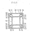
- the guidance means has typically a structure as illustrated in Figure 5.
- a pair of guidance rollers 72 are supported rotatably by a pair of brackets 71 at each top corner of an inside beam 70.
- the rollers roll on an inner surface of an outside beam 60 when the extendable beam is extended or retracted.
- the beam 60 may be provided with additional rollers at lower positions if necessary.
- the guidance roller 72 rolls around a bolt 73 which horizontally extends through the bracket 71.
- a nut 74 prevents the bolt from falling out of the bracket.
- the bolt 73 and nut 74 may be replaced by a split pin.
- a general object of the present invention is to provide a guidance means for the extension of the multiple beam of which maintenance can be easily achieved.
- the fixed and movable beams are provided with a roller supporting member at least at the bottom inside each corner.
- the roller supporting member bears a number of rollers, which roll on a ridge of a beam directly inside the beam to let the inside beam smoothly go up or down.
- the roller supporting member can be detached from the beam and drawn underneath out of the beam together with the roller beared by the member. After the roller, as well as other elements attached to the member, is inspected or exchanged, the supporting member is inserted in the beam along the ridge to be fixed again inside the corner.
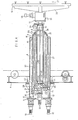
- Figure 2 illustrates an overhead traveling crane with a crab to which the extendable multiple beam of the present invention is attached.
- a pair of rails 1 are set up in a building H.
- a girder 2 is mounted on the rails 1 to be movable on the rails.
- Figure 3 illustrates the girder 2.
- Another pair of rails 3 are set up on the girder 2 and a crab 4 runs on the rails 3.
- An extendable multiple beam 5 is attached to the crab 4 as illustrated in Figures 2 and 4.
- the multiple beam 5 consists of a beam 6, which is fixed under the crab 4, and four movable beams 7-10.
- the cross-sections of the fixed and movable beams are similar to each other though the size of the cross-sections becomes smaller from beam to beam.
- the cross-section of the beams is formed square in this embodiment.
- the movable beams 7-10 are inserted in the fixed beam 6 and movable beams 7-9 respectively so that the former ones can go up and down in the latter ones.
- a carrier 12 is attached to the bottom of the multiple beam 5 by way of a rotating and raising device 11.
- a pair of threaded shafts 13 extend through the fixed beam 6 from the top to the bottom by way of a pair of nuts 14 respectively, which nuts are both fixed to the outer surface of the first movable beam 7.
- the shafts 13 are rotated by motors 15 set up on the roof of the multiple beam 5, the nuts 14 and accordingly the first movable beam 7 are driven up or down in the fixed beam 6.
- the bottom 16 of the first beam 7 is connected to the roof 20 of the second movable beam 8 by way of a pair of eyebolts 19, chains 17, sprockets 18 on the roof of the first movable beam 7, and eyebolts 21.
- Another threaded shaft 23 is suspended through the second, third and fourth movable beams 8, 9 and 10.
- the shaft 23 is rotated by a motor 25 set up on the roof 20 of the second beam 8.
- the third beam 9 is provided with a nut 24 on its roof. The nut 24 is engaged with the shaft 23 to climb or descend the shaft together with the third beam 9 when the shaft is rotated.
- the bottom 26 of the second beam 8 is connected to the roof 30 of the fourth beam 10 by way of a pair of eyebolts 29, chains 27, sprockets 28 on the roof of the third movable beam 9 and eyebolts 31.
- the fourth beam 10 thereby goes up or down twice as fast as the third beam 9 in the same direction.
- a guidance board 32 is rotatably provided at the bottom end of the threaded shaft 23, with guidance rollers 33 on its periphery which can roll on the inner surface of the fourth beam 10.
- the equipment of the guidance board 32 and guidance rollers 33 is well known to those skilled in the art and not described in detail.
- Figure 1 is a cross-sectional view of the extendable multiple beam 5. The structure of the beam 5 is described below in detail with reference to Figure 1.
- the fixed beam 6 for instance comprises wall members 6a and corner members 6b.
- the members 6a and 6b have flanges 6c and 6d respectively, by which they are connected to each other.
- a roller supporting member 52 formed to fit well the inside of the corner member 6b is inserted in each of the corner members 6b. It is fastened to the corner member 6b in a detachable manner at a predetermined position, for example by means of screws 55 which are driven into the supporting member from outside the corner member.
- the roller supporting member 52 is provided with a number of rotatable shafts 53 which horizontally cross diagonals of the beam 6. Each of the shafts 53 bears also rotatably a guidance roller 54, which rolls on a ridge of the first movable beam 7.
- the periphery 54a of the roller 54 is cut into V-shape to hold firmly the ridge of the beam 7 to prevent the beam from rotation in relation to the fixed beam 6 with the smallest number of the rollers 54.
- the interval between the rollers 54 in the roller supporting member is determined so that the swinging of the beam 7 in the fixed beam 6 is effectively prevented, 1m for example.
- a passage 56 is provided to supply lubricant such as grease between the supporting member 52 and each shaft 53 as well as each shaft 53 and guidance roller 54.
- the passages are open to the air by way of nipples not illustrated in the drawing.
- the movable beams 7-9 also comprise wall members 7a-9a and corner members 7b-9b respectively.
- the supporting member is also inserted and fixed in the corner members 7b-9b to direct the movement of the beams 8-10 respectively.
- a rotating and raising device 11 attached to the bottom of the fourth movable beam 10 comprises motors 34 and 35 to rotate and raise a carrier 12.
- the carrier 12 comprises a frame 36 equipped with vacuum absorption devices 37, as well as lifting magnets not illustrated in the drawings, at the bottom.
- the girder 2 is equipped at both ends with motors 39 to drive the girder, as illustrated in Figure 3.
- the crab 4 is equipped with a motor 40 to drive the crab, a vacuum pump 41 and vacuum tank 42 for the vacuum absorption devices 37, and a control board 44. Electricity is supplied to the vacuum pump 41, as well as to the motors 15, 25, 34, 35, 39 and 40, as well known to those skilled in the art. Such supply of electricity is controlled by means of the control board 44 on the crab 4 which is capable of radio traffic with a control panel 43 in the operator's hands.
- a number of rotary encoders are used to detect the position of the carrier 12 during the operation.
- a rotary encoder 46 is attached to the girder 2 and geared to a rack 45 which is laid along one of the rails 1. Signals are provided from the encoder to indicate the positions of the girder 2 on the rails 1.
- Another rotary encoder 48 is attached to the crab 4 and geared to another rack 47 which is laid along one of the rails 3. Signals are also provided from the encoder to indicate the positions of the crab 4 on the rails 3.
- Two other rotary encoders 49 and 50 are geared with the sprockets 18 and 28 on the first and third movable beams 7 and 9 respectively to determine the height of the carrier 12.
- the rotating and raising device 11 also comprises a rotary encoder 51 to detect the inclination of the carrier 12. Another is attached to the bottom of the beam 10 to detect the rotation of the carrier, though not illustrated in the drawings. Every information obtained by the rotary encoders are displayed on the control panel 43.
- the movement of the movable beams 7-10 is directed by the guidance rollers 54.
- the members 52 which support the rollers 54 are fixed in the corner members 6b-9b of the beams 6-9 with the screws 55.
- the members are able to be detached from the corner members easily by loosening the screws.
- the inspection or exchange of the rollers 54 is thus easily achieved by detaching and extracting the members 52 beneath out of the corner members. After the maintenance works have been completed, they are again inserted in the corner members and fixed at the original positions with screws.
- the maintenance of the guidance rollers as well as of other elements pertaining to the rollers which is a very difficult work in the prior art, can be dealt with very easily as a result.
Abstract
Description
- The present invention relates to an overhead taveling crane with a crab and more particulary to a guidance means for the extension of a beam which is attached to the crab to hang a carrier and comprises a number of movable beams.
- A extendable multiple beam attached to the crab usually comprises a beam fixed under the crab and a number of beams inserted movably into the fixed beam one after the other in order of size. A guidance means is usually interposed between the fixed and movable beams to let the movable beams smoothly go up and down in the fixed beam.
- The guidance means has typically a structure as illustrated in Figure 5. A pair of
guidance rollers 72 are supported rotatably by a pair ofbrackets 71 at each top corner of aninside beam 70. The rollers roll on an inner surface of anoutside beam 60 when the extendable beam is extended or retracted. Thebeam 60 may be provided with additional rollers at lower positions if necessary. - The
guidance roller 72 rolls around abolt 73 which horizontally extends through thebracket 71. Anut 74 prevents the bolt from falling out of the bracket. Thebolt 73 andnut 74 may be replaced by a split pin. - Because of the large number of elements to be arranged in a narrow space between the inside and
outside beams - A general object of the present invention is to provide a guidance means for the extension of the multiple beam of which maintenance can be easily achieved. According to the invention, the fixed and movable beams are provided with a roller supporting member at least at the bottom inside each corner. The roller supporting member bears a number of rollers, which roll on a ridge of a beam directly inside the beam to let the inside beam smoothly go up or down.
- The roller supporting member can be detached from the beam and drawn underneath out of the beam together with the roller beared by the member. After the roller, as well as other elements attached to the member, is inspected or exchanged, the supporting member is inserted in the beam along the ridge to be fixed again inside the corner.
- Other objects and aspects of the present invention will become apparent from the following description when taken with reference to the accompanying drawings, in which:
- Figure 1 is a cross-sectional view of an extendable multiple beam of the present invention.
- Figure 2 is a front view of a girder carrying a crab to which the extendable multiple beam of the present invention is applied.
- Figure 3 is a plan view of the girder crab as illustrated in Figure 2.
- Figure 4 is a vertical sectional view of the crab with the extendable multiple beam of the present invention.
- Figure 5 is a cross-sectional view of an extendable multiple beam of the prior art.
- Figure 2 illustrates an overhead traveling crane with a crab to which the extendable multiple beam of the present invention is attached. A pair of
rails 1 are set up in a buildingH. A girder 2 is mounted on therails 1 to be movable on the rails. Figure 3 illustrates thegirder 2. Another pair ofrails 3 are set up on thegirder 2 and acrab 4 runs on therails 3. An extendablemultiple beam 5 is attached to thecrab 4 as illustrated in Figures 2 and 4. Themultiple beam 5 consists of abeam 6, which is fixed under thecrab 4, and four movable beams 7-10. The cross-sections of the fixed and movable beams are similar to each other though the size of the cross-sections becomes smaller from beam to beam. The cross-section of the beams is formed square in this embodiment. The movable beams 7-10 are inserted in thefixed beam 6 and movable beams 7-9 respectively so that the former ones can go up and down in the latter ones. Additionally, acarrier 12 is attached to the bottom of themultiple beam 5 by way of a rotating and raisingdevice 11. - The structure of the
multiple beam 5 is described below in more detail with reference to Figure 4. A pair of threadedshafts 13 extend through thefixed beam 6 from the top to the bottom by way of a pair ofnuts 14 respectively, which nuts are both fixed to the outer surface of the firstmovable beam 7. When theshafts 13 are rotated bymotors 15 set up on the roof of themultiple beam 5, thenuts 14 and accordingly the firstmovable beam 7 are driven up or down in thefixed beam 6. - The
bottom 16 of thefirst beam 7 is connected to theroof 20 of the secondmovable beam 8 by way of a pair ofeyebolts 19,chains 17,sprockets 18 on the roof of the firstmovable beam 7, andeyebolts 21. As a result, when thefirst beam 7 goes up or down, thesecond beam 8 proceeds twice as fast as the first beam in the same direction. - Another threaded
shaft 23 is suspended through the second, third and fourthmovable beams shaft 23 is rotated by amotor 25 set up on theroof 20 of thesecond beam 8. Thethird beam 9 is provided with a nut 24 on its roof. The nut 24 is engaged with theshaft 23 to climb or descend the shaft together with thethird beam 9 when the shaft is rotated. - The
bottom 26 of thesecond beam 8 is connected to the roof 30 of thefourth beam 10 by way of a pair ofeyebolts 29,chains 27,sprockets 28 on the roof of the thirdmovable beam 9 andeyebolts 31. Thefourth beam 10 thereby goes up or down twice as fast as thethird beam 9 in the same direction. Additionally, a guidance board 32 is rotatably provided at the bottom end of the threadedshaft 23, withguidance rollers 33 on its periphery which can roll on the inner surface of thefourth beam 10. The equipment of the guidance board 32 andguidance rollers 33 is well known to those skilled in the art and not described in detail. - Figure 1 is a cross-sectional view of the extendable
multiple beam 5. The structure of thebeam 5 is described below in detail with reference to Figure 1. - The
fixed beam 6 for instance compriseswall members 6a andcorner members 6b. Themembers flanges - A
roller supporting member 52 formed to fit well the inside of thecorner member 6b is inserted in each of thecorner members 6b. It is fastened to thecorner member 6b in a detachable manner at a predetermined position, for example by means ofscrews 55 which are driven into the supporting member from outside the corner member. - The
roller supporting member 52 is provided with a number ofrotatable shafts 53 which horizontally cross diagonals of thebeam 6. Each of theshafts 53 bears also rotatably aguidance roller 54, which rolls on a ridge of the firstmovable beam 7. - Preferably the
periphery 54a of theroller 54 is cut into V-shape to hold firmly the ridge of thebeam 7 to prevent the beam from rotation in relation to thefixed beam 6 with the smallest number of therollers 54. The interval between therollers 54 in the roller supporting member is determined so that the swinging of thebeam 7 in thefixed beam 6 is effectively prevented, 1m for example. - Also preferably, a
passage 56 is provided to supply lubricant such as grease between the supportingmember 52 and eachshaft 53 as well as eachshaft 53 andguidance roller 54. The passages are open to the air by way of nipples not illustrated in the drawing. - The movable beams 7-9 also comprise
wall members 7a-9a andcorner members 7b-9b respectively. The supporting member is also inserted and fixed in thecorner members 7b-9b to direct the movement of the beams 8-10 respectively. - A rotating and raising
device 11 attached to the bottom of the fourthmovable beam 10 comprisesmotors carrier 12. Thecarrier 12 comprises aframe 36 equipped withvacuum absorption devices 37, as well as lifting magnets not illustrated in the drawings, at the bottom. - The
girder 2 is equipped at both ends withmotors 39 to drive the girder, as illustrated in Figure 3. Thecrab 4 is equipped with amotor 40 to drive the crab, avacuum pump 41 andvacuum tank 42 for thevacuum absorption devices 37, and acontrol board 44. Electricity is supplied to thevacuum pump 41, as well as to themotors control board 44 on thecrab 4 which is capable of radio traffic with acontrol panel 43 in the operator's hands. - A number of rotary encoders are used to detect the position of the
carrier 12 during the operation. A rotary encoder 46 is attached to thegirder 2 and geared to arack 45 which is laid along one of therails 1. Signals are provided from the encoder to indicate the positions of thegirder 2 on therails 1. Another rotary encoder 48 is attached to thecrab 4 and geared to anotherrack 47 which is laid along one of therails 3. Signals are also provided from the encoder to indicate the positions of thecrab 4 on therails 3. Two otherrotary encoders 49 and 50 are geared with thesprockets movable beams carrier 12. - The rotating and raising
device 11 also comprises arotary encoder 51 to detect the inclination of thecarrier 12. Another is attached to the bottom of thebeam 10 to detect the rotation of the carrier, though not illustrated in the drawings. Every information obtained by the rotary encoders are displayed on thecontrol panel 43. - As described above, the movement of the movable beams 7-10 is directed by the
guidance rollers 54. Themembers 52 which support therollers 54 are fixed in thecorner members 6b-9b of the beams 6-9 with thescrews 55. The members are able to be detached from the corner members easily by loosening the screws. The inspection or exchange of therollers 54 is thus easily achieved by detaching and extracting themembers 52 beneath out of the corner members. After the maintenance works have been completed, they are again inserted in the corner members and fixed at the original positions with screws. The maintenance of the guidance rollers as well as of other elements pertaining to the rollers, which is a very difficult work in the prior art, can be dealt with very easily as a result.
Claims (6)
a roller supporting member fixed inside the first beam along a corner of it at a predetermined position in an easily detachable way;
a shaft rotatably supported in the roller supporting member so that its axis horizontally crosses a diagonal of the first beam at a right angle;
a roller rotatably supported by the shaft which rolls on a corner of the second beam when the second beam moves upwards or downwards in the first beam.
a number of wall members each having flanges on both sides;
the same number of corner members each having flanges on both sides, which flanges are bound together with the flanges of the wall members to make up the separate beam;
the same number of roller supporting members inserted in the corner members respectively and fixed at a predetermined position in an easily detachable way;
a shaft rotatably supported in each of the roller supporting members so that its axis horizontally crosses a diagonal of the separate beam at a right angle when the roller supporting member is fixed in the corner member;
a roller rotatably supported by the shaft which is in touch with a corner of another separate beam situated directly inside the beam and rolls on the corner when the inside beam moves upwards or downwards in the beam.
Applications Claiming Priority (2)
| Application Number | Priority Date | Filing Date | Title |
|---|---|---|---|
| JP171190/87 | 1987-11-09 | ||
| JP1987171190U JPH0175088U (en) | 1987-11-09 | 1987-11-09 |
Publications (2)
| Publication Number | Publication Date |
|---|---|
| EP0316151A1 true EP0316151A1 (en) | 1989-05-17 |
| EP0316151B1 EP0316151B1 (en) | 1992-04-08 |
Family
ID=15918678
Family Applications (1)
| Application Number | Title | Priority Date | Filing Date |
|---|---|---|---|
| EP19880310543 Expired - Lifetime EP0316151B1 (en) | 1987-11-09 | 1988-11-09 | Overhead traveling crane |
Country Status (3)
| Country | Link |
|---|---|
| EP (1) | EP0316151B1 (en) |
| JP (1) | JPH0175088U (en) |
| DE (1) | DE3869910D1 (en) |
Cited By (2)
| Publication number | Priority date | Publication date | Assignee | Title |
|---|---|---|---|---|
| ES2113264A1 (en) * | 1993-08-02 | 1998-04-16 | Franz Ehrenleitner | Suspension device for the suspension of loads and corresponding C-hook |
| EP2759497A4 (en) * | 2012-03-08 | 2015-06-10 | Advanced Mft Tech Ct Cn Camst | Sarong transportation apparatus |
Citations (8)
| Publication number | Priority date | Publication date | Assignee | Title |
|---|---|---|---|---|
| GB782070A (en) * | 1955-09-15 | 1957-08-28 | Asea Ab | Guide means for a load handling device travelling on overhead rails |
| US3082881A (en) * | 1960-04-20 | 1963-03-26 | Wieger Ernst | Telescopically variable overhang beam for dredges, cranes, and the like |
| US3095945A (en) * | 1959-12-22 | 1963-07-02 | Lift A Loft Corp | Overhead service unit |
| US3109545A (en) * | 1959-12-15 | 1963-11-05 | Gen Mills Inc | Telescopic material handling support |
| FR1415329A (en) * | 1964-12-01 | 1965-10-22 | Ver Flugtechnische Werke | Height-adjustable work platform |
| FR1527526A (en) * | 1967-06-16 | 1968-05-31 | Gottwald Kg Leo | Telescopic crane boom |
| DE3149411A1 (en) * | 1980-12-31 | 1982-08-19 | The Warner & Swasey Co., 44106 Cleveland, Ohio | Jib of a derrick for the loading of goods |
| DE3528996C1 (en) * | 1985-08-13 | 1986-12-18 | Mannesmann AG, 4000 Düsseldorf | Telescopic column |
-
1987
- 1987-11-09 JP JP1987171190U patent/JPH0175088U/ja active Pending
-
1988
- 1988-11-09 DE DE8888310543T patent/DE3869910D1/en not_active Expired - Fee Related
- 1988-11-09 EP EP19880310543 patent/EP0316151B1/en not_active Expired - Lifetime
Patent Citations (8)
| Publication number | Priority date | Publication date | Assignee | Title |
|---|---|---|---|---|
| GB782070A (en) * | 1955-09-15 | 1957-08-28 | Asea Ab | Guide means for a load handling device travelling on overhead rails |
| US3109545A (en) * | 1959-12-15 | 1963-11-05 | Gen Mills Inc | Telescopic material handling support |
| US3095945A (en) * | 1959-12-22 | 1963-07-02 | Lift A Loft Corp | Overhead service unit |
| US3082881A (en) * | 1960-04-20 | 1963-03-26 | Wieger Ernst | Telescopically variable overhang beam for dredges, cranes, and the like |
| FR1415329A (en) * | 1964-12-01 | 1965-10-22 | Ver Flugtechnische Werke | Height-adjustable work platform |
| FR1527526A (en) * | 1967-06-16 | 1968-05-31 | Gottwald Kg Leo | Telescopic crane boom |
| DE3149411A1 (en) * | 1980-12-31 | 1982-08-19 | The Warner & Swasey Co., 44106 Cleveland, Ohio | Jib of a derrick for the loading of goods |
| DE3528996C1 (en) * | 1985-08-13 | 1986-12-18 | Mannesmann AG, 4000 Düsseldorf | Telescopic column |
Cited By (2)
| Publication number | Priority date | Publication date | Assignee | Title |
|---|---|---|---|---|
| ES2113264A1 (en) * | 1993-08-02 | 1998-04-16 | Franz Ehrenleitner | Suspension device for the suspension of loads and corresponding C-hook |
| EP2759497A4 (en) * | 2012-03-08 | 2015-06-10 | Advanced Mft Tech Ct Cn Camst | Sarong transportation apparatus |
Also Published As
| Publication number | Publication date |
|---|---|
| JPH0175088U (en) | 1989-05-22 |
| DE3869910D1 (en) | 1992-05-14 |
| EP0316151B1 (en) | 1992-04-08 |
Similar Documents
| Publication | Publication Date | Title |
|---|---|---|
| JP2587684B2 (en) | Construction wall construction equipment | |
| JPS59188596A (en) | Reactor pressure vessel under side device | |
| JPH055987B2 (en) | ||
| US2869734A (en) | Hoist unit | |
| US4319677A (en) | Stockyard transporter and tripper car equipment | |
| EP0316151B1 (en) | Overhead traveling crane | |
| CN110985091B (en) | Flue plate laying machine suitable for large-diameter flue plates and laying method thereof | |
| CN116788984A (en) | Rail mounted container portal crane | |
| CN201167442Y (en) | Apparatus for supporting wiring template | |
| CN215431698U (en) | Large-span circular track processing machine | |
| CN210029833U (en) | Lifting equipment for building construction | |
| JPH07292964A (en) | Device for construction work of building wall surface | |
| JPH0319567Y2 (en) | ||
| CN216196749U (en) | Building engineering construction platform | |
| CN217760429U (en) | Shielding device for repairing building engineering wall | |
| CN217536747U (en) | Existing railway sound barrier positioning and guiding device | |
| CN218539065U (en) | Adjustable beam lifting machine | |
| JP2564945B2 (en) | Steel tower automatic assembly method and automatic assembly system therefor | |
| CN213872024U (en) | Monitor for community security | |
| JPH07207928A (en) | Construction facility of structure | |
| KR100226988B1 (en) | An up-down moving device of robot | |
| JP2545152B2 (en) | Floor material holding device for crane | |
| CN207580846U (en) | A kind of mobile suction means of middle-placed switch cabinet plank | |
| JP3005780B2 (en) | Construction lifting equipment | |
| JP3700105B2 (en) | Ground member assembly equipment |
Legal Events
| Date | Code | Title | Description |
|---|---|---|---|
| PUAI | Public reference made under article 153(3) epc to a published international application that has entered the european phase |
Free format text: ORIGINAL CODE: 0009012 |
|
| AK | Designated contracting states |
Kind code of ref document: A1 Designated state(s): DE FR GB IT |
|
| 17P | Request for examination filed |
Effective date: 19891114 |
|
| 17Q | First examination report despatched |
Effective date: 19910313 |
|
| GRAA | (expected) grant |
Free format text: ORIGINAL CODE: 0009210 |
|
| AK | Designated contracting states |
Kind code of ref document: B1 Designated state(s): DE FR GB IT |
|
| ITF | It: translation for a ep patent filed |
Owner name: JACOBACCI & PERANI S.P.A. |
|
| REF | Corresponds to: |
Ref document number: 3869910 Country of ref document: DE Date of ref document: 19920514 |
|
| ET | Fr: translation filed | ||
| PGFP | Annual fee paid to national office [announced via postgrant information from national office to epo] |
Ref country code: GB Payment date: 19921102 Year of fee payment: 5 |
|
| PGFP | Annual fee paid to national office [announced via postgrant information from national office to epo] |
Ref country code: FR Payment date: 19921130 Year of fee payment: 5 |
|
| PGFP | Annual fee paid to national office [announced via postgrant information from national office to epo] |
Ref country code: DE Payment date: 19921211 Year of fee payment: 5 |
|
| PLBE | No opposition filed within time limit |
Free format text: ORIGINAL CODE: 0009261 |
|
| STAA | Information on the status of an ep patent application or granted ep patent |
Free format text: STATUS: NO OPPOSITION FILED WITHIN TIME LIMIT |
|
| 26N | No opposition filed | ||
| PG25 | Lapsed in a contracting state [announced via postgrant information from national office to epo] |
Ref country code: GB Effective date: 19931109 |
|
| GBPC | Gb: european patent ceased through non-payment of renewal fee |
Effective date: 19931109 |
|
| PG25 | Lapsed in a contracting state [announced via postgrant information from national office to epo] |
Ref country code: FR Effective date: 19940729 |
|
| PG25 | Lapsed in a contracting state [announced via postgrant information from national office to epo] |
Ref country code: DE Effective date: 19940802 |
|
| REG | Reference to a national code |
Ref country code: FR Ref legal event code: ST |
|
| PG25 | Lapsed in a contracting state [announced via postgrant information from national office to epo] |
Ref country code: IT Free format text: LAPSE BECAUSE OF NON-PAYMENT OF DUE FEES;WARNING: LAPSES OF ITALIAN PATENTS WITH EFFECTIVE DATE BEFORE 2007 MAY HAVE OCCURRED AT ANY TIME BEFORE 2007. THE CORRECT EFFECTIVE DATE MAY BE DIFFERENT FROM THE ONE RECORDED. Effective date: 20051109 |