EP0316076B1 - Vibration controlling apparatus for buildings - Google Patents
Vibration controlling apparatus for buildings Download PDFInfo
- Publication number
- EP0316076B1 EP0316076B1 EP88309680A EP88309680A EP0316076B1 EP 0316076 B1 EP0316076 B1 EP 0316076B1 EP 88309680 A EP88309680 A EP 88309680A EP 88309680 A EP88309680 A EP 88309680A EP 0316076 B1 EP0316076 B1 EP 0316076B1
- Authority
- EP
- European Patent Office
- Prior art keywords
- vibration
- building
- additional mass
- controlling apparatus
- buildings
- Prior art date
- Legal status (The legal status is an assumption and is not a legal conclusion. Google has not performed a legal analysis and makes no representation as to the accuracy of the status listed.)
- Expired - Lifetime
Links
- 230000005284 excitation Effects 0.000 claims description 11
- 229920001971 elastomer Polymers 0.000 claims description 10
- 239000000806 elastomer Substances 0.000 claims description 7
- 238000010030 laminating Methods 0.000 claims description 7
- 230000003014 reinforcing effect Effects 0.000 claims description 6
- 230000001133 acceleration Effects 0.000 claims description 2
- 239000003638 chemical reducing agent Substances 0.000 description 24
- 230000001276 controlling effect Effects 0.000 description 20
- 238000013016 damping Methods 0.000 description 9
- 230000001603 reducing effect Effects 0.000 description 9
- 230000000087 stabilizing effect Effects 0.000 description 7
- 230000000694 effects Effects 0.000 description 5
- 239000005060 rubber Substances 0.000 description 3
- 230000015556 catabolic process Effects 0.000 description 2
- 238000010276 construction Methods 0.000 description 2
- 238000006731 degradation reaction Methods 0.000 description 2
- 238000010586 diagram Methods 0.000 description 2
- 239000004033 plastic Substances 0.000 description 2
- 230000003068 static effect Effects 0.000 description 2
- 229910000831 Steel Inorganic materials 0.000 description 1
- 230000002411 adverse Effects 0.000 description 1
- 239000010426 asphalt Substances 0.000 description 1
- 230000005540 biological transmission Effects 0.000 description 1
- 239000004927 clay Substances 0.000 description 1
- 238000007796 conventional method Methods 0.000 description 1
- 230000003247 decreasing effect Effects 0.000 description 1
- 238000006073 displacement reaction Methods 0.000 description 1
- 239000007788 liquid Substances 0.000 description 1
- 239000007937 lozenge Substances 0.000 description 1
- 239000002184 metal Substances 0.000 description 1
- 239000010959 steel Substances 0.000 description 1
- 239000000126 substance Substances 0.000 description 1
- XLYOFNOQVPJJNP-UHFFFAOYSA-N water Substances O XLYOFNOQVPJJNP-UHFFFAOYSA-N 0.000 description 1
Images




Classifications
-
- E—FIXED CONSTRUCTIONS
- E02—HYDRAULIC ENGINEERING; FOUNDATIONS; SOIL SHIFTING
- E02D—FOUNDATIONS; EXCAVATIONS; EMBANKMENTS; UNDERGROUND OR UNDERWATER STRUCTURES
- E02D31/00—Protective arrangements for foundations or foundation structures; Ground foundation measures for protecting the soil or the subsoil water, e.g. preventing or counteracting oil pollution
- E02D31/08—Protective arrangements for foundations or foundation structures; Ground foundation measures for protecting the soil or the subsoil water, e.g. preventing or counteracting oil pollution against transmission of vibrations or movements in the foundation soil
-
- E—FIXED CONSTRUCTIONS
- E04—BUILDING
- E04H—BUILDINGS OR LIKE STRUCTURES FOR PARTICULAR PURPOSES; SWIMMING OR SPLASH BATHS OR POOLS; MASTS; FENCING; TENTS OR CANOPIES, IN GENERAL
- E04H9/00—Buildings, groups of buildings or shelters adapted to withstand or provide protection against abnormal external influences, e.g. war-like action, earthquake or extreme climate
- E04H9/02—Buildings, groups of buildings or shelters adapted to withstand or provide protection against abnormal external influences, e.g. war-like action, earthquake or extreme climate withstanding earthquake or sinking of ground
- E04H9/021—Bearing, supporting or connecting constructions specially adapted for such buildings
- E04H9/0215—Bearing, supporting or connecting constructions specially adapted for such buildings involving active or passive dynamic mass damping systems
Definitions
- This invention relates to a vibration controlling apparatus for buildings which reduces the swaying in a building of a flexible structure system such as a high-rise building, tower or the like due to an earthquake, wind or the like.
- a dynamic vibration reducer i.e. dynamic damper
- a dynamic vibration reducer for the generation of vibration counteracting the swaying of the building, which comprises a combination of a main spring system consisting of the building itself and an auxiliary spring system connected to the building through a spring means and provided with an additional mass and is set so that the natural frequency (vibration period) is approximately equal between the main spring system and the auxiliary spring system to realize the vibration absorbing effect.
- Fig. 13 shows a structure of this type of conventional dynamic vibration reducer.
- a lower mass 33 movable along a pair of rails 32 horizontally placed on a building 31 (e.g. on top of a tower or the like) in a given direction (Y-direction) and an upper mass 35 movable along a pair of rails 34 horizontally placed on the lower mass 33 in a given direction (X-direction) are supported by spring members (not shown) extending in the Y-direction and X-direction, respectively.
- each of these masses 33, 35 is slidably supported by a roll having a small friction coefficient, respectively.
- the conventional dynamic vibration reducer for the building is a two-dimensional apparatus, wherein the dynamic vibration reducing effect to the vibration (swaying) of the building 31 in the Y-direction is obtained by the auxiliary spring system consisting of springs of the Y-direction and the upper mass 35 and lower mass 33, and the dynamic vibration reducing effect to the vibration (swaying) in the X-direction is obtained by the auxiliary spring system consisting of springs of the X-direction and the upper mass 35.
- the main spring system and auxiliary spring system having substantially the same vibration period are merely connected to each other (passive damper), so that if it is intended to make the vibration controlling effect large, the mass ratio of the building 31 to additional masses 33, 35 becomes large (in a direction approaching to 1.0) and consequently it is required to increase the strength of the building 31, which is difficult to practically realize.
- the vibration response ratio is determined by the masses 33, 35, spring constant and vibration damping coefficient of the dynamic vibration reducer (auxiliary spring system).
- this apparatus has a large effect for a particular vibration frequency component, but can not provide the vibration reducing effect against vibrations of wide frequency band such as random vibration.
- each of the masses 33, 35 is supported by a roll bearing or the like, so that the static friction coefficient is large in the vibration reducing operation and consequently only the reducing effect against the large external force is obtained and the effect against minute vibration cannot be obtained.
- JP-A-59,97341 reflects the preamble of claim 1 and discloses a vibration controlling apparatus for buildings comprising an additional mass attached to the building and means for applying an excitation force of a given waveform corresponding to vibration of the building to the additional mass.
- the present invention aims to overcome the aforementioned problems of the conventional techniques and to provide a vibration controlling apparatus for buildings which can largely reduce the vibrations (swaying) of the building over the whole of a wide frequency band and can respond immediately to small vibrations because the friction sliding portion is not existent even in the vibration reducing operation.
- a vibration controlling apparatus for buildings comprising an additional mass attached to a building and means for applying an excitation force of a given waveform corresponding to vibration of said building to said additional mass, to excite the additional mass in a direction opposite to an acceleration undergone by the building, characterized in that said means for applying an excitation force to said additional mass comprises a vibration sensor for detecting a vibration of said building, and means for forming an excitation force of a given waveform based on the detected signal, and transmitting it to an actuator which is at one end connected to the building and at its other end to the said additional mass, and in that the additional mass is attached to the building through an elastic support means utilizing a lateral elasticity of a laminated elastic body obtained by alternately laminating an elastomer layer and a reinforcing plate one upon the other.
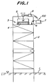
- Fig. 1 schematically shows a building provided with the vibration controlling apparatus according to the invention.
- a tower-like building 2 is built on a ground 1, and the vibration controlling apparatus 100 according to the invention is placed on a top floor of the building 2.
- a steel structure building having a section of square, rectangle, lozenge or the like with a side of, for example, 10-25 m and a height of 60-150 m and swaying, for example, at a vibration period of about 2 seconds and an amplitude of few meters through wind pressure, and the like.
- an additional mass 5 is attached to the building 2 through a horizontal spring means 4 to construct a dynamic vibration reducer 3, while the vibration (swaying) of the building 2 is detected by a vibration sensor 6 and then a vibration waveform counteracting the vibration of the building 2 is produced by a control unit 7 based on the detected signal and vibration is applied to the additional mass 5 by an actuator 8 actuating based on the vibration waveform to thereby reduce the swaying of the building 2.
- the horizontal spring means or elastic support means 4 acts to elastically support the additional mass 5 to the building 2 at a horizontally displaceable state and has a structure utilizing the lateral elasticity of a laminated elastic body (rubber laminate) obtained by alternately laminating an elastomer layer and a reinforcing plate one upon the other as mentioned later.
- the vibration controlling apparatus 100 comprises the dynamic vibration reducer 3 consisting of a main vibration system of the building 2 and an auxiliary spring system connecting thereto and composed of the horizontal spring means 4 and the additional mass 5 having substantially the same vibration period and can effectively reduce the swaying of the building 2 by producing a vibration waveform counteracting the vibration state of the building 2 and then vibrating the additional mass 5 through the actuator 8 actuating based on the vibration waveform even when the building 2 is subjected to various excitation forces of a wide frequency band.
- Fig. 2 shows a front view of the auxiliary spring system constituting the dynamic vibration reducer
- Fig. 3 shows a transversely sectional view taken along a line III-III of Fig. 2.
- the dynamic vibration reducer 3 is constructed by the spring means 4 utilizing the lateral elasticity of the laminated elastic body 11 and the additional mass 5 attached onto the spring means.
- the spring means 4 is comprised of multi-stage elastic units by piling plural laminated elastic bodies (4 bodies) one upon the other (4 stages) through stabilizing plates 12 each connecting the lower end of the body 11 to the upper end of the other body 11.
- Each of these stabilizing plates 12 is a rigid plate and serves to increase an elastical and horizontal displacement ability without causing buckling when the plate is subjected to lateral loading by earthquake or wind.
- a damping device 13 for damping vibrations in the horizontal direction is incorporated between the adjoining stabilizing plates 12, 12 in a given arrangement.
- the spring means (elastic support means) 4 may be comprised of a single laminated elastic body 11.
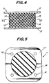
- Fig. 4 shows a longitudinally sectional view of the laminated elastic body 11, and Fig. 5 shows a section taken along a line V-V of Fig. 4.
- the laminated elastic body 11 has a structure of alternately laminating a layer 14 of rubber or other elastomer and a reinforcing plate 15 such as metal plate or rigid plastic plate one upon the other, and flange plates 17, 17 each having plural fitting holes 16 are usually bonded to the upper and lower ends of the body 11 by baking, adhesion or the like.
- Such a laminated elastic body 11 has a high spring constant in the longitudinal direction and a relatively low spring constant in the horizontal direction.
- Fig. 6 shows a longitudinally sectional view of the dynamic vibration reducer 3 having a mode correcting rod
- Fig. 7 shows a section taken along a line VII-VII of Fig. 6.
- FIGs. 6 and 7 plural through-holes 51 are formed at given positions (5 positions in the illustrated embodiment) in each of the stabilizing plates 12, and a mode correcting rod 52 is inserted into each of these through-holes 51.
- the lower end of the mode correcting rod 52 is pivoted to the building 2 through a pivot point 53, while the upper end thereof is engaged to the additional mass 5.
- the through-hole 51 in the stabilizing plate 12 has such a diameter that the mode correcting rod 52 is freely inserted into the through-hole at a certain gap.
- the mode correcting rod 52 is to correct the distortion of vibration mode in horizontal direction of the multi-stage laminated elastic body unit and prevent the degradation of the vibration damping effect.
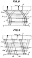
- Fig. 8 schematically shows a vibration mode of the dynamic vibration reducer 3 having no mode correcting rod 52
- Fig. 9 schematically shows a vibration mode of the dynamic vibration reducer 3 having the mode correcting rod 52.
- the distortion of the vibration mode as shown in Fig. 8 is avoided by extending the mode correcting rod 52 from the building 2 through each of the stabilizing plates 12 to the additional mass 5, whereby the dynamic vibration reducer for the building capable of holding the linearity and preventing the degradation of the damping effect is obtained.
- Fig. 10 shows a block diagram illustrating the construction of the vibration controlling apparatus 100 shown in Fig. 1.
- the vibration controlling apparatus 100 is constructed to reduce the vibration or swaying of the building 2 by attaching the additional mass 5 to the building 2 through the spring means (elastic support means) 4 explained in Fig. 2, and detecting vibrations generated in the building 2, and applying an excitation force of a given waveform adjusted in accordance with the vibration of the building 2 to the additional mass 5.
- the control circuit 7 is so constructed that a vibration waveform of a component counteracting the vibration of the building 2 is produced based on a detected signal from vibration sensor 6 detecting the vibration (swaying) of the building 2 to thereby actuate the actuator 8 and then the waveform counteracting the vibration of the building 2 is applied to the additional mass 5.
- the control circuit 7 is comprised by connecting a charge amplifier 21, a low-pass filter 22, an analog-digital convertor 23, a digital filter 24, a digital-analog convertor 25, a low-pass filter 26 and a power amplifier (signal amplifier) 27 in order, and functions to output a vibration waveform counteracting the vibration of the building 2 from the power amplifier 27 based on the detected signal for the vibration of the building 2 input from the vibration sensor 6 into the charge amplifier 21.
- the output from the power amplifier 27 is input to the actuator 8, so that the actuator 8 excites the additional mass 5 at a state of counteracting the vibration of the building 2 and as a result the dynamic vibration reducer 3 acts as an active dynamic damper.
- the digital filter 24 has a most important function of forming the waveform signal in the control circuit 7.
- the additional mass 5 is separated from the actuator 8 to shut off the transmission of excitation force, whereby the dynamic vibration reducer 3 consisting of the additional mass 5 and the elastic support means (spring means) 4 can be used as an active dynamic damper.
- the illustrated dynamic vibration reducer 3 is comprised of the auxiliary spring system having substantially the same natural frequency as in the building (main spring system) 2, so that it possesses a function that a large vibration in the vicinity of resonant frequency of the building 2 is effectively damped together with the passive damper.
- the vibration state of the building 2 is detected by the vibration sensor 6 arranged on the building 2, and then a signal calculated from the detected signal by the control circuit 7 so as to reduce the vibration of the building is input to the actuator 8 to thereby actuate the active dynamic vibration reducer (dynamic damper), so that the reducer has a structure of small size and light weight. Therefore, a vibration controlling apparatus capable of effectively reducing vibrations over a whole frequency band is obtained even when the building 2 is excited by the external force of the wide frequency band.
- the spring of the dynamic vibration reducer 3 is constructed by utilizing the lateral elasticity of the laminated elastic body 11, so that the static friction force can be eliminated, and consequently a vibration controlling apparatus capable of surely responding to small external force is obtained.
- a laminated elastic body 11 having uniform spring properties in all of the two-dimensional directions is used, so that the structure of the dynamic vibration reducer 3 can be made simple and cheap.
- the multi-stage elastomer unit is formed by laminating plural laminated elastic bodies 11 through the stabilizing plates 12 (for example, about 10 stages), even after the unit is assembled on the building 2, the dynamic vibration damping characteristics can easily be adjusted by increasing or decreasing the number of the stages, and consequently a vibration controlling apparatus having an excellent handling property is obtained.
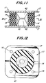
- Fig. 11 shows another embodiment of the laminated elastic body 11
- Fig. 12 shows a sectional view taken along a line XII-XII of Fig. 11.
- a hollow portion 41 of a closed state is formed in a central portion of the laminated elastic body 11 obtained by alternately laminating the elastomer layer 14 and the reinforcing plate 15 one upon the other, and a vibration damping means having an increased internal loss is arranged in the hollow portion 41.
- each of protrusions 42, 42 projecting toward the hollow portion 41 is formed on the inner face of each of the flange plates 17, 17 constituting both end faces of the laminated elastic body, while a liquid or viscous fluidizing substance (water, oil, green rubber, plastic, asphalt, clay or the like) is filled in the hollow portion 41.
- a liquid or viscous fluidizing substance water, oil, green rubber, plastic, asphalt, clay or the like
- the vibration damping performances may further be improved by utilizing the vibration damping means arranged in the hollow portion as compared with the case of Figs. 4 and 5.
- the additional mass is attached through the elastic spring means utilizing the lateral elasticity of the laminated elastic body obtained by alternately laminating the elastomer layer and the reinforcing plate one upon the other, and the excitation force of a given waveform in accordance with the vibration of the building is applied to the additional mass, so that the apparatus is small in size and light in weight, and also the vibrations can effectively be reduced over the whole of the wide frequency range. Furthermore, a vibration controlling apparatus capable of surely responding to small external force to reduce the swaying is obtained.
Landscapes
- Engineering & Computer Science (AREA)
- Architecture (AREA)
- Environmental & Geological Engineering (AREA)
- Structural Engineering (AREA)
- Life Sciences & Earth Sciences (AREA)
- Emergency Management (AREA)
- Business, Economics & Management (AREA)
- Civil Engineering (AREA)
- Hydrology & Water Resources (AREA)
- General Engineering & Computer Science (AREA)
- Paleontology (AREA)
- Mining & Mineral Resources (AREA)
- General Life Sciences & Earth Sciences (AREA)
- Buildings Adapted To Withstand Abnormal External Influences (AREA)
- Vibration Prevention Devices (AREA)
Description
- This invention relates to a vibration controlling apparatus for buildings which reduces the swaying in a building of a flexible structure system such as a high-rise building, tower or the like due to an earthquake, wind or the like.
- In high buildings such as high-rise buildings, various towers and the like, there is adopted a flexible structure system for absorbing vibration energy to increase the earthquake proof strength.
- In this flexible structure system, however, the swaying is not only caused by a strong wind or earthquake but also becomes large even at normal wind, so that the living comfortability may be adversely affected.
- As a means for reducing the vibration amplitude at normal wind to improve the living comfortability and at the same time reducing the deformation of the building as a whole even in a strong wind or earthquake, therefore, it has been proposed to arrange a dynamic vibration reducer (i.e. dynamic damper) for the generation of vibration counteracting the swaying of the building, which comprises a combination of a main spring system consisting of the building itself and an auxiliary spring system connected to the building through a spring means and provided with an additional mass and is set so that the natural frequency (vibration period) is approximately equal between the main spring system and the auxiliary spring system to realize the vibration absorbing effect. Fig. 13 shows a structure of this type of conventional dynamic vibration reducer.
- As shown in Fig. 13, a
lower mass 33 movable along a pair ofrails 32 horizontally placed on a building 31 (e.g. on top of a tower or the like) in a given direction (Y-direction) and anupper mass 35 movable along a pair ofrails 34 horizontally placed on thelower mass 33 in a given direction (X-direction) are supported by spring members (not shown) extending in the Y-direction and X-direction, respectively. Further, each of thesemasses - Thus, the conventional dynamic vibration reducer for the building is a two-dimensional apparatus, wherein the dynamic vibration reducing effect to the vibration (swaying) of the
building 31 in the Y-direction is obtained by the auxiliary spring system consisting of springs of the Y-direction and theupper mass 35 andlower mass 33, and the dynamic vibration reducing effect to the vibration (swaying) in the X-direction is obtained by the auxiliary spring system consisting of springs of the X-direction and theupper mass 35. - In the conventional vibration controlling apparatus for buildings, however, the main spring system and auxiliary spring system having substantially the same vibration period are merely connected to each other (passive damper), so that if it is intended to make the vibration controlling effect large, the mass ratio of the
building 31 toadditional masses building 31, which is difficult to practically realize. - Since the conventional vibration controlling apparatus is a passive damper as mentioned above, the vibration response ratio is determined by the
masses - Further, each of the
masses - JP-A-59,97341 reflects the preamble of claim 1 and discloses a vibration controlling apparatus for buildings comprising an additional mass attached to the building and means for applying an excitation force of a given waveform corresponding to vibration of the building to the additional mass.
- The present invention aims to overcome the aforementioned problems of the conventional techniques and to provide a vibration controlling apparatus for buildings which can largely reduce the vibrations (swaying) of the building over the whole of a wide frequency band and can respond immediately to small vibrations because the friction sliding portion is not existent even in the vibration reducing operation.
- According to the invention, there is provided a vibration controlling apparatus for buildings, comprising an additional mass attached to a building and means for applying an excitation force of a given waveform corresponding to vibration of said building to said additional mass, to excite the additional mass in a direction opposite to an acceleration undergone by the building, characterized in that said means for applying an excitation force to said additional mass comprises a vibration sensor for detecting a vibration of said building, and means for forming an excitation force of a given waveform based on the detected signal, and transmitting it to an actuator which is at one end connected to the building and at its other end to the said additional mass, and in that the additional mass is attached to the building through an elastic support means utilizing a lateral elasticity of a laminated elastic body obtained by alternately laminating an elastomer layer and a reinforcing plate one upon the other.
- The invention will be further described by way of example only, with reference to the accompanying drawings, wherein:
- Fig. 1 is a schematic elevational view of a building provided with a vibration controlling apparatus according to the invention;
- Fig. 2 is a front view of a dynamic vibration reducer shown in Fig. 1;
- Fig. 3 is a sectional view taken along a line III-III of Fig. 2;
- Fig. 4 is a longitudinally sectional view of a laminated elastic body shown in Fig. 2;
- Fig. 5 is a sectional view taken along a line V-V of Fig. 4;
- Fig. 6 is a front view of another embodiment of the dynamic vibration reducer;
- Fig. 7 is a transversely sectional view taken along a line VII-VII of Fig. 6;
- Fig. 8 is a diagrammatical view showing a vibration mode of the dynamic vibration reducer having no mode correcting rod;
- Fig. 9 is a diagrammatical view showing a vibration mode of the dynamic vibration reducer having a mode correcting rod;
- Fig. 10 is a block diagram showing the construction of the vibration controlling apparatus according to the invention;
- Fig. 11 is a longitudinally sectional view of another embodiment of the laminated elastic body of Fig. 2;
- Fig. 12 is a sectional view taken along a line XII-XII of Fig. 11; and
- Fig. 13 is a perspective view of the conventional dynamic vibration reducer for a building.
- The invention will be described in detail with reference to Figs. 1 to 12 below.
- Fig. 1 schematically shows a building provided with the vibration controlling apparatus according to the invention.
- In Fig. 1, a tower-
like building 2 is built on a ground 1, and thevibration controlling apparatus 100 according to the invention is placed on a top floor of thebuilding 2. - As a typical example of the
building 2, mention may be made of a steel structure building having a section of square, rectangle, lozenge or the like with a side of, for example, 10-25 m and a height of 60-150 m and swaying, for example, at a vibration period of about 2 seconds and an amplitude of few meters through wind pressure, and the like. - In the
vibration controlling apparatus 100, anadditional mass 5 is attached to thebuilding 2 through a horizontal spring means 4 to construct adynamic vibration reducer 3, while the vibration (swaying) of thebuilding 2 is detected by avibration sensor 6 and then a vibration waveform counteracting the vibration of thebuilding 2 is produced by acontrol unit 7 based on the detected signal and vibration is applied to theadditional mass 5 by anactuator 8 actuating based on the vibration waveform to thereby reduce the swaying of thebuilding 2. - The horizontal spring means or elastic support means 4 acts to elastically support the
additional mass 5 to thebuilding 2 at a horizontally displaceable state and has a structure utilizing the lateral elasticity of a laminated elastic body (rubber laminate) obtained by alternately laminating an elastomer layer and a reinforcing plate one upon the other as mentioned later. - That is, the
vibration controlling apparatus 100 comprises thedynamic vibration reducer 3 consisting of a main vibration system of thebuilding 2 and an auxiliary spring system connecting thereto and composed of the horizontal spring means 4 and theadditional mass 5 having substantially the same vibration period and can effectively reduce the swaying of thebuilding 2 by producing a vibration waveform counteracting the vibration state of thebuilding 2 and then vibrating theadditional mass 5 through theactuator 8 actuating based on the vibration waveform even when thebuilding 2 is subjected to various excitation forces of a wide frequency band. - Fig. 2 shows a front view of the auxiliary spring system constituting the dynamic vibration reducer, and Fig. 3 shows a transversely sectional view taken along a line III-III of Fig. 2.
- In Figs. 2 and 3, the
dynamic vibration reducer 3 is constructed by the spring means 4 utilizing the lateral elasticity of the laminated elastic body 11 and theadditional mass 5 attached onto the spring means. - In the illustrated embodiment, the
spring means 4 is comprised of multi-stage elastic units by piling plural laminated elastic bodies (4 bodies) one upon the other (4 stages) through stabilizingplates 12 each connecting the lower end of the body 11 to the upper end of the other body 11. - Each of these stabilizing
plates 12 is a rigid plate and serves to increase an elastical and horizontal displacement ability without causing buckling when the plate is subjected to lateral loading by earthquake or wind. - In the illustrated embodiment, a
damping device 13 for damping vibrations in the horizontal direction is incorporated between the adjoining stabilizingplates - If necessary, the spring means (elastic support means) 4 may be comprised of a single laminated elastic body 11.
- Fig. 4 shows a longitudinally sectional view of the laminated elastic body 11, and Fig. 5 shows a section taken along a line V-V of Fig. 4.
- In Figs. 4 and 5, the laminated elastic body 11 has a structure of alternately laminating a
layer 14 of rubber or other elastomer and a reinforcingplate 15 such as metal plate or rigid plastic plate one upon the other, andflange plates plural fitting holes 16 are usually bonded to the upper and lower ends of the body 11 by baking, adhesion or the like. - Such a laminated elastic body 11 has a high spring constant in the longitudinal direction and a relatively low spring constant in the horizontal direction.
- Fig. 6 shows a longitudinally sectional view of the
dynamic vibration reducer 3 having a mode correcting rod, and Fig. 7 shows a section taken along a line VII-VII of Fig. 6. - In Figs. 6 and 7, plural through-
holes 51 are formed at given positions (5 positions in the illustrated embodiment) in each of the stabilizingplates 12, and amode correcting rod 52 is inserted into each of these through-holes 51. - The lower end of the
mode correcting rod 52 is pivoted to thebuilding 2 through apivot point 53, while the upper end thereof is engaged to theadditional mass 5. - Moreover, the through-
hole 51 in the stabilizingplate 12 has such a diameter that themode correcting rod 52 is freely inserted into the through-hole at a certain gap. - The
mode correcting rod 52 is to correct the distortion of vibration mode in horizontal direction of the multi-stage laminated elastic body unit and prevent the degradation of the vibration damping effect. - Fig. 8 schematically shows a vibration mode of the dynamic vibration reducer 3 having no
mode correcting rod 52, while Fig. 9 schematically shows a vibration mode of the dynamic vibration reducer 3 having themode correcting rod 52. - As seen from Figs. 8 and 9, the distortion of the vibration mode as shown in Fig. 8 is avoided by extending the
mode correcting rod 52 from thebuilding 2 through each of the stabilizingplates 12 to theadditional mass 5, whereby the dynamic vibration reducer for the building capable of holding the linearity and preventing the degradation of the damping effect is obtained. - Fig. 10 shows a block diagram illustrating the construction of the
vibration controlling apparatus 100 shown in Fig. 1. - The
vibration controlling apparatus 100 according to the invention is constructed to reduce the vibration or swaying of thebuilding 2 by attaching theadditional mass 5 to thebuilding 2 through the spring means (elastic support means) 4 explained in Fig. 2, and detecting vibrations generated in thebuilding 2, and applying an excitation force of a given waveform adjusted in accordance with the vibration of thebuilding 2 to theadditional mass 5. - In Fig. 10, the
control circuit 7 is so constructed that a vibration waveform of a component counteracting the vibration of thebuilding 2 is produced based on a detected signal fromvibration sensor 6 detecting the vibration (swaying) of thebuilding 2 to thereby actuate theactuator 8 and then the waveform counteracting the vibration of thebuilding 2 is applied to theadditional mass 5. - As shown in Fig. 10, the
control circuit 7 is comprised by connecting acharge amplifier 21, a low-pass filter 22, an analog-digital convertor 23, adigital filter 24, a digital-analog convertor 25, a low-pass filter 26 and a power amplifier (signal amplifier) 27 in order, and functions to output a vibration waveform counteracting the vibration of thebuilding 2 from thepower amplifier 27 based on the detected signal for the vibration of thebuilding 2 input from thevibration sensor 6 into thecharge amplifier 21. - The output from the
power amplifier 27 is input to theactuator 8, so that theactuator 8 excites theadditional mass 5 at a state of counteracting the vibration of thebuilding 2 and as a result the dynamic vibration reducer 3 acts as an active dynamic damper. - The
digital filter 24 has a most important function of forming the waveform signal in thecontrol circuit 7. - If the control signal output from the
control circuit 7 exceeds the capacity of theactuator 8, theadditional mass 5 is separated from theactuator 8 to shut off the transmission of excitation force, whereby the dynamic vibration reducer 3 consisting of theadditional mass 5 and the elastic support means (spring means) 4 can be used as an active dynamic damper. - That is, the illustrated
dynamic vibration reducer 3 is comprised of the auxiliary spring system having substantially the same natural frequency as in the building (main spring system) 2, so that it possesses a function that a large vibration in the vicinity of resonant frequency of thebuilding 2 is effectively damped together with the passive damper. - According to the above mentioned embodiment, the vibration state of the
building 2 is detected by thevibration sensor 6 arranged on thebuilding 2, and then a signal calculated from the detected signal by thecontrol circuit 7 so as to reduce the vibration of the building is input to theactuator 8 to thereby actuate the active dynamic vibration reducer (dynamic damper), so that the reducer has a structure of small size and light weight. Therefore, a vibration controlling apparatus capable of effectively reducing vibrations over a whole frequency band is obtained even when thebuilding 2 is excited by the external force of the wide frequency band. - Further, the spring of the
dynamic vibration reducer 3 is constructed by utilizing the lateral elasticity of the laminated elastic body 11, so that the static friction force can be eliminated, and consequently a vibration controlling apparatus capable of surely responding to small external force is obtained. - Also, a laminated elastic body 11 having uniform spring properties in all of the two-dimensional directions is used, so that the structure of the
dynamic vibration reducer 3 can be made simple and cheap. - Moreover, when the multi-stage elastomer unit is formed by laminating plural laminated elastic bodies 11 through the stabilizing plates 12 (for example, about 10 stages), even after the unit is assembled on the
building 2, the dynamic vibration damping characteristics can easily be adjusted by increasing or decreasing the number of the stages, and consequently a vibration controlling apparatus having an excellent handling property is obtained. - Fig. 11 shows another embodiment of the laminated elastic body 11, and Fig. 12 shows a sectional view taken along a line XII-XII of Fig. 11.
- In Figs. 11 and 12, a
hollow portion 41 of a closed state is formed in a central portion of the laminated elastic body 11 obtained by alternately laminating theelastomer layer 14 and the reinforcingplate 15 one upon the other, and a vibration damping means having an increased internal loss is arranged in thehollow portion 41. - In the illustrated embodiment, each of
protrusions hollow portion 41 is formed on the inner face of each of theflange plates hollow portion 41. - In the laminated elastic body 11 shown in Figs. 11 and 12, the vibration damping performances may further be improved by utilizing the vibration damping means arranged in the hollow portion as compared with the case of Figs. 4 and 5.
- As mentioned above, in the vibration controlling apparatus for buildings according to the invention, the additional mass is attached through the elastic spring means utilizing the lateral elasticity of the laminated elastic body obtained by alternately laminating the elastomer layer and the reinforcing plate one upon the other, and the excitation force of a given waveform in accordance with the vibration of the building is applied to the additional mass, so that the apparatus is small in size and light in weight, and also the vibrations can effectively be reduced over the whole of the wide frequency range. Furthermore, a vibration controlling apparatus capable of surely responding to small external force to reduce the swaying is obtained.
Claims (1)
- A vibration controlling apparatus (100) for buildings, comprising an additional mass (5) attached to a building (2) and means for applying an excitation force of a given waveform corresponding to vibration of said building to said additional mass, to excite the additional mass in a direction opposite to an acceleration undergone by the building, characterized in that said means for applying an excitation force to said additional mass comprises a vibration sensor (6) for detecting a vibration of said building, and means for forming an excitation force of a given waveform based on the detected signal, and transmitting it to an actuator (8) which is at one end connected to the building and at its other end to the said additional mass, and in that the additional mass is attached to the building through an elastic support means (4) utilizing a lateral elasticity of a laminated elastic body (11) obtained by alternately laminating an elastomer layer and a reinforcing plate one upon the other.
Priority Applications (1)
| Application Number | Priority Date | Filing Date | Title |
|---|---|---|---|
| EP92203145A EP0525919B1 (en) | 1987-10-16 | 1988-10-14 | Vibration controlling apparatus for buildings |
Applications Claiming Priority (2)
| Application Number | Priority Date | Filing Date | Title |
|---|---|---|---|
| JP261239/87 | 1987-10-16 | ||
| JP62261239A JP2617106B2 (en) | 1987-10-16 | 1987-10-16 | Building vibration control device |
Related Child Applications (2)
| Application Number | Title | Priority Date | Filing Date |
|---|---|---|---|
| EP92203145.5 Division-Into | 1988-10-14 | ||
| EP92203145A Division EP0525919B1 (en) | 1987-10-16 | 1988-10-14 | Vibration controlling apparatus for buildings |
Publications (2)
| Publication Number | Publication Date |
|---|---|
| EP0316076A1 EP0316076A1 (en) | 1989-05-17 |
| EP0316076B1 true EP0316076B1 (en) | 1994-04-13 |
Family
ID=17359071
Family Applications (2)
| Application Number | Title | Priority Date | Filing Date |
|---|---|---|---|
| EP88309680A Expired - Lifetime EP0316076B1 (en) | 1987-10-16 | 1988-10-14 | Vibration controlling apparatus for buildings |
| EP92203145A Expired - Lifetime EP0525919B1 (en) | 1987-10-16 | 1988-10-14 | Vibration controlling apparatus for buildings |
Family Applications After (1)
| Application Number | Title | Priority Date | Filing Date |
|---|---|---|---|
| EP92203145A Expired - Lifetime EP0525919B1 (en) | 1987-10-16 | 1988-10-14 | Vibration controlling apparatus for buildings |
Country Status (4)
| Country | Link |
|---|---|
| US (1) | US4924640A (en) |
| EP (2) | EP0316076B1 (en) |
| JP (1) | JP2617106B2 (en) |
| DE (2) | DE3889072T2 (en) |
Families Citing this family (24)
| Publication number | Priority date | Publication date | Assignee | Title |
|---|---|---|---|---|
| US5373670A (en) * | 1988-05-06 | 1994-12-20 | Sumitomo Gomu Kogyo Kabushiki Kaisha | Shakeproof bearing |
| JPH03250165A (en) * | 1990-02-27 | 1991-11-07 | Shimizu Corp | Hybrid dynamic vibration reducer |
| JP2589590B2 (en) * | 1990-09-25 | 1997-03-12 | 株式会社フジタ | Damping device |
| US5259159A (en) * | 1990-11-08 | 1993-11-09 | Shimizu Construction Co., Ltd | Construction having a damping device |
| JPH086493B2 (en) * | 1991-05-29 | 1996-01-24 | 鹿島建設株式会社 | Vibration control device for structures |
| JPH086494B2 (en) * | 1991-06-07 | 1996-01-24 | 鹿島建設株式会社 | Vibration control device for structures |
| JP2927573B2 (en) * | 1991-06-11 | 1999-07-28 | 辰治 石丸 | Structure damping device |
| JP2546454B2 (en) * | 1991-08-23 | 1996-10-23 | 鹿島建設株式会社 | Vibration control device for structures |
| JP2546465B2 (en) * | 1992-01-28 | 1996-10-23 | 鹿島建設株式会社 | Vibration control device for structures |
| JPH05222863A (en) * | 1992-02-14 | 1993-08-31 | Kajima Corp | Vibration control device for structures |
| JP2598497Y2 (en) * | 1992-06-17 | 1999-08-09 | 日立金属株式会社 | Vibration control actuator and vibration control device using this vibration control actuator |
| JPH0932341A (en) * | 1995-07-21 | 1997-02-04 | Kenji Okayasu | Rocket damper |
| TW295612B (en) * | 1995-07-21 | 1997-01-11 | Minnesota Mining & Mfg | |
| US6115972A (en) * | 1996-04-09 | 2000-09-12 | Tamez; Federico Garza | Structure stabilization system |
| WO2001075329A1 (en) * | 2000-03-31 | 2001-10-11 | Virginia Tech Intellectual Properties, Inc. | Net control system of structural vibrations |
| JP4070213B2 (en) * | 2004-06-07 | 2008-04-02 | 学校法人金沢工業大学 | Vibration control device and long structure |
| CN100516394C (en) * | 2005-12-02 | 2009-07-22 | 卢锐 | Laminated steel plate energy-dissipation shock-absorbing damp |
| DE102006022430B4 (en) * | 2006-05-13 | 2010-12-09 | Wölfel Beratende Ingenieure GmbH & Co. KG | Building ceiling with absorber |
| DE102006042424B3 (en) * | 2006-09-09 | 2007-10-04 | Ip-Analysis Ag | Vibration-damping-device for building, has control device producing control signal in acceleration-device on basis of load-signal for acceleration of counterweight, where counterweight is movably supported in shaft |
| JP5325082B2 (en) * | 2009-12-08 | 2013-10-23 | 中部電力株式会社 | Multistage seismic isolation device |
| CN101769016B (en) * | 2010-03-09 | 2011-07-27 | 张德新 | Anti-seismic device of building |
| JP6049524B2 (en) * | 2013-03-29 | 2016-12-21 | 中部電力株式会社 | Seismic isolation device |
| KR101525741B1 (en) * | 2014-07-29 | 2015-06-04 | 단국대학교 산학협력단 | Calculating and control Method of optimal control force of active mass damper |
| JP6706551B2 (en) * | 2016-06-28 | 2020-06-10 | 鹿島建設株式会社 | Vibration control device, vibration control system, and vibration control method |
Family Cites Families (16)
| Publication number | Priority date | Publication date | Assignee | Title |
|---|---|---|---|---|
| FR984959A (en) * | 1943-10-19 | 1951-07-12 | Lightweight building with thermally and acoustically insulated rooms | |
| DE2816345A1 (en) * | 1978-04-14 | 1979-10-25 | Vki Rheinhold & Mahla Ag | Vibration absorber for use in shipbuilding - has flexible vibration absorbing body with inserted masses altering vibration frequency |
| SU838014A1 (en) * | 1979-09-21 | 1981-06-15 | Ленинградский Ордена Ленина Институтинженеров Железнодорожного Транспортаим. Акад. B.H.Образцова | Arrangement for protecting structure in earthquake |
| SU962557A1 (en) * | 1980-06-06 | 1982-09-30 | Тбилисский зональный научно-исследовательский и проектный институт типового и экспериментального проектирования жилых и общественных зданий | Earthquake-proof multistorey building |
| US4429496A (en) * | 1980-12-24 | 1984-02-07 | University Of Southern California | Method and apparatus for active control of flexible structures |
| NZ201015A (en) * | 1982-06-18 | 1986-05-09 | New Zealand Dev Finance | Building support:cyclic shear energy absorber |
| JPS5997341A (en) * | 1982-11-22 | 1984-06-05 | Mitsubishi Electric Corp | Device for restraining vibration of structural body |
| US4593501A (en) * | 1983-10-11 | 1986-06-10 | Isosys, Inc. | Vibration and shock isolator with adjustable stiffness |
| JPS60164520A (en) * | 1984-02-08 | 1985-08-27 | Mitsubishi Electric Corp | Earthquake resisting device |
| FR2560265A1 (en) * | 1984-02-28 | 1985-08-30 | Ciccolini Jacques | ANISISMIC DEVICE COMPRISING ELASTOMER SPRINGS AND WIND STABILIZERS AND BUILDING USING SUCH A DEVICE |
| NZ208129A (en) * | 1984-05-11 | 1988-10-28 | New Zealand Dev Finance | Shear energy absorber: confined granular material within deformable block |
| SU1193245A2 (en) * | 1984-05-18 | 1985-11-23 | Московский Инженерно-Строительный Институт Им.В.В.Куйбышева | Pendulum-type oscillation damper for flexible structures |
| JPS61165044A (en) * | 1985-01-16 | 1986-07-25 | Kajima Corp | Vibration, earthquake isolator |
| US4635892A (en) * | 1985-08-19 | 1987-01-13 | Vibrastop, Inc. | Active vibration suppressor |
| SU1301948A1 (en) * | 1985-11-25 | 1987-04-07 | Алма-Атинский Архитектурно-Строительный Институт | Pendulum-type dynamic oscillation damper |
| US4799339A (en) * | 1986-05-16 | 1989-01-24 | Kajima Corporation | Method of controlling building against earthquake |
-
1987
- 1987-10-16 JP JP62261239A patent/JP2617106B2/en not_active Expired - Lifetime
-
1988
- 1988-10-14 EP EP88309680A patent/EP0316076B1/en not_active Expired - Lifetime
- 1988-10-14 DE DE3889072T patent/DE3889072T2/en not_active Expired - Fee Related
- 1988-10-14 DE DE3856415T patent/DE3856415T2/en not_active Expired - Fee Related
- 1988-10-14 US US07/257,892 patent/US4924640A/en not_active Expired - Lifetime
- 1988-10-14 EP EP92203145A patent/EP0525919B1/en not_active Expired - Lifetime
Also Published As
| Publication number | Publication date |
|---|---|
| JP2617106B2 (en) | 1997-06-04 |
| DE3856415D1 (en) | 2000-07-06 |
| US4924640A (en) | 1990-05-15 |
| EP0316076A1 (en) | 1989-05-17 |
| EP0525919A2 (en) | 1993-02-03 |
| EP0525919A3 (en) | 1993-04-07 |
| EP0525919B1 (en) | 2000-05-31 |
| DE3889072T2 (en) | 1994-09-22 |
| DE3856415T2 (en) | 2001-06-28 |
| DE3889072D1 (en) | 1994-05-19 |
| JPH01105879A (en) | 1989-04-24 |
Similar Documents
| Publication | Publication Date | Title |
|---|---|---|
| US4924640A (en) | Vibration controlling apparatus for buildings | |
| US5339580A (en) | Laminated rubber building support and vibration damping device | |
| US5487534A (en) | Laminated rubber vibration control device for structures | |
| EP1948878B1 (en) | Structure with increased damping by means of fork configuration dampers | |
| US8851460B2 (en) | System and method for tuning the resonance frequency of an energy absorbing device for a structure in response to a disruptive force | |
| EP0586701A1 (en) | Vibration control device for structure | |
| EP0587891B1 (en) | Vibration control device for structure | |
| EP0556033A1 (en) | Vibration control device for structure | |
| JPH04102742A (en) | Earthquakeproof supporting device | |
| RU2535567C2 (en) | Quakeproof building | |
| JP2001182776A (en) | Sliding bearing seismic isolation device | |
| JP2660340B2 (en) | Dynamic vibration absorber for buildings | |
| US6364064B1 (en) | Piezoceramic elevator vibration attenuator | |
| JP2889329B2 (en) | Control method of dynamic vibration absorber device for building | |
| JP2816344B2 (en) | Laminated rubber bearing | |
| JP2938095B2 (en) | Dynamic vibration absorber for buildings | |
| JPH0483070A (en) | Support struction of roof installation | |
| JP2940731B2 (en) | Structure vibration control device | |
| JP6635327B2 (en) | Seismic isolation structure of building and seismic isolation method | |
| JP3463085B2 (en) | Seismic building | |
| JPH11303918A (en) | Seismic isolation system and seismic isolation structure for structures | |
| JP2615644B2 (en) | Seismic isolation device | |
| JPH0542202Y2 (en) | ||
| JPH0689615B2 (en) | Stopper device for building vibration control device | |
| JPH03288038A (en) | Variable characteristic earthquake-isolating device and variable characteristic earthquake-isolating system |
Legal Events
| Date | Code | Title | Description |
|---|---|---|---|
| PUAI | Public reference made under article 153(3) epc to a published international application that has entered the european phase |
Free format text: ORIGINAL CODE: 0009012 |
|
| AK | Designated contracting states |
Kind code of ref document: A1 Designated state(s): DE FR GB |
|
| 17P | Request for examination filed |
Effective date: 19890901 |
|
| 17Q | First examination report despatched |
Effective date: 19900212 |
|
| GRAA | (expected) grant |
Free format text: ORIGINAL CODE: 0009210 |
|
| RAP1 | Party data changed (applicant data changed or rights of an application transferred) |
Owner name: FUJITA, TAKAFUMI Owner name: BRIDGESTONE CORPORATION |
|
| AK | Designated contracting states |
Kind code of ref document: B1 Designated state(s): DE FR GB |
|
| XX | Miscellaneous (additional remarks) |
Free format text: TEILANMELDUNG 92203145.5 EINGEREICHT AM 14/10/88. |
|
| REF | Corresponds to: |
Ref document number: 3889072 Country of ref document: DE Date of ref document: 19940519 |
|
| ET | Fr: translation filed | ||
| PLBE | No opposition filed within time limit |
Free format text: ORIGINAL CODE: 0009261 |
|
| STAA | Information on the status of an ep patent application or granted ep patent |
Free format text: STATUS: NO OPPOSITION FILED WITHIN TIME LIMIT |
|
| 26N | No opposition filed | ||
| REG | Reference to a national code |
Ref country code: GB Ref legal event code: IF02 |
|
| PGFP | Annual fee paid to national office [announced via postgrant information from national office to epo] |
Ref country code: GB Payment date: 20061011 Year of fee payment: 19 |
|
| PGFP | Annual fee paid to national office [announced via postgrant information from national office to epo] |
Ref country code: DE Payment date: 20061012 Year of fee payment: 19 |
|
| GBPC | Gb: european patent ceased through non-payment of renewal fee |
Effective date: 20071014 |
|
| PG25 | Lapsed in a contracting state [announced via postgrant information from national office to epo] |
Ref country code: DE Free format text: LAPSE BECAUSE OF NON-PAYMENT OF DUE FEES Effective date: 20080501 |
|
| REG | Reference to a national code |
Ref country code: FR Ref legal event code: ST Effective date: 20080630 |
|
| PGFP | Annual fee paid to national office [announced via postgrant information from national office to epo] |
Ref country code: FR Payment date: 20061010 Year of fee payment: 19 |
|
| PG25 | Lapsed in a contracting state [announced via postgrant information from national office to epo] |
Ref country code: GB Free format text: LAPSE BECAUSE OF NON-PAYMENT OF DUE FEES Effective date: 20071014 |
|
| PG25 | Lapsed in a contracting state [announced via postgrant information from national office to epo] |
Ref country code: FR Free format text: LAPSE BECAUSE OF NON-PAYMENT OF DUE FEES Effective date: 20071031 |