EP0315932A2 - Folding machine in a rotary press - Google Patents
Folding machine in a rotary press Download PDFInfo
- Publication number
- EP0315932A2 EP0315932A2 EP88118524A EP88118524A EP0315932A2 EP 0315932 A2 EP0315932 A2 EP 0315932A2 EP 88118524 A EP88118524 A EP 88118524A EP 88118524 A EP88118524 A EP 88118524A EP 0315932 A2 EP0315932 A2 EP 0315932A2
- Authority
- EP
- European Patent Office
- Prior art keywords
- distributor
- belts
- pair
- section
- folded sheets
- Prior art date
- Legal status (The legal status is an assumption and is not a legal conclusion. Google has not performed a legal analysis and makes no representation as to the accuracy of the status listed.)
- Granted
Links
Images


Classifications
-
- B—PERFORMING OPERATIONS; TRANSPORTING
- B65—CONVEYING; PACKING; STORING; HANDLING THIN OR FILAMENTARY MATERIAL
- B65H—HANDLING THIN OR FILAMENTARY MATERIAL, e.g. SHEETS, WEBS, CABLES
- B65H5/00—Feeding articles separated from piles; Feeding articles to machines
- B65H5/02—Feeding articles separated from piles; Feeding articles to machines by belts or chains, e.g. between belts or chains
- B65H5/021—Feeding articles separated from piles; Feeding articles to machines by belts or chains, e.g. between belts or chains by belts
- B65H5/023—Feeding articles separated from piles; Feeding articles to machines by belts or chains, e.g. between belts or chains by belts between a pair of belts forming a transport nip
-
- B—PERFORMING OPERATIONS; TRANSPORTING
- B41—PRINTING; LINING MACHINES; TYPEWRITERS; STAMPS
- B41F—PRINTING MACHINES OR PRESSES
- B41F13/00—Common details of rotary presses or machines
- B41F13/54—Auxiliary folding, cutting, collecting or depositing of sheets or webs
- B41F13/56—Folding or cutting
-
- B—PERFORMING OPERATIONS; TRANSPORTING
- B65—CONVEYING; PACKING; STORING; HANDLING THIN OR FILAMENTARY MATERIAL
- B65H—HANDLING THIN OR FILAMENTARY MATERIAL, e.g. SHEETS, WEBS, CABLES
- B65H2404/00—Parts for transporting or guiding the handled material
- B65H2404/20—Belts
- B65H2404/24—Longitudinal profile
- B65H2404/243—Longitudinal profile with portions of different thickness
-
- B—PERFORMING OPERATIONS; TRANSPORTING
- B65—CONVEYING; PACKING; STORING; HANDLING THIN OR FILAMENTARY MATERIAL
- B65H—HANDLING THIN OR FILAMENTARY MATERIAL, e.g. SHEETS, WEBS, CABLES
- B65H2404/00—Parts for transporting or guiding the handled material
- B65H2404/20—Belts
- B65H2404/26—Particular arrangement of belt, or belts
- B65H2404/261—Arrangement of belts, or belt(s) / roller(s) facing each other for forming a transport nip
Abstract
Description
- The present invention relates to a folding machine in a rotary press.
- One example of the known folding machine in a rotary press in the prior art is illustrated in Fig. 5(a). In this figure, successive sheets cut out from a web by means of a pair of rotating
cutter drums 10 and 11 are led to a distributor section D as pinched between a pair ofconveyor belts conveyor belt 25 and theconveyor belt 12 on the downstream side of atapered guide 23 and conveyed to arotary runner 34 in a gathering station at the lower stream. The remainder of the cut sheets distributed to the other direction are likewise pinched between anotherconveyor belt 26 and theconveyor belt 13 on the downstream side of thetapered guide 23 and conveyed to arotary runner 50 at the lower stream. In this way, the successive sheets cut out by thecutter drums 10 and 11 are distributed alternately to different directions and gathered at different gathering stations. - A detailed structure of the distributor section D is shown in Figs. 6 and 7. On
shafts guide rolls conveyor belts guide rolls cam surfaces tapered guide 23 having a pair of diverging sheet guide surfaces 23a and 23b consisting of concave surfaces is provided between theconveyor belts cam surfaces 60a (61a) provided on the rotary sheet diverters 60 (61) are adapted to be interlaced with each other in the widthwise direction of the sheet. - Distribution of the sheets is carried out in the following manner. When the cut sheets SA and SB (See Fig. 5(b)) are alternately and continuously fed to between the rotary sheet diverters 60 and 61 by the
conveyor belts conveyor belt 12 by theprotruded cam surface 61a of therotary sheet diverter 61, subsequently the sheet SA is delivered into a sheet receiving gap formed by theconveyor belts rotary runner 34 existing on the downstream side as pinched by thebelts protruded cam surface 61a has been rotated to a position outside of the route for the sheet SB and instead theprotruded cam surface 60a of therotary sheet diverter 60 has entered the route for the sheet SB, hence the sheet SB is diverted into the flow path formed between the sheet guide surface 23b and theconveyor belt 13, and it is sent to therotary runner 50 that is different from that for the sheet SA by theconveyor belts cam surface 60a has been rotated to a position outside of the route for the sheet SA, hence thecam surface 61a again returns into the traveling route for the sheet SA, and the above-described sequence of operations is repeated. - In addition, after the
conveyor belts rolls rolls conveyor belt 12 is formed into one route of divergent routes by means of therotary guide rolls tapered guide 23 it forms a closed route jointly with anotherbelt 25 and cooperates therewith to send the distributed sheets to the collecting station. Likewise, after passing through the rotary guide rolls 19 and 20, theconveyor belt 13 cooperates with anotherbelt 26 to send the distributed sheets to the collecting station. In this way, theconveyor belts - However, the cam surfaces in the distributor section in the prior art merely perform distribution of sheets in the diverging space formed by a pair of conveyor belts, they do not have a capability of conveying a sheet as positively holding it, accordingly upon passing through the distributor section, a thin paper sheet or a sheet having a small area was liable to produce waving, scratching, creasing and paper blocking, and so, a stability was poor.
- Also, since the cam plates and the conveyor belts are disposed in a meshed condition in the widthwise direction of the sheets, it was impossible that both the cam plate surface and the conveyor surface support the sheet edge portions which present the most unstable behavior among the entire width of the sheets, and accordingly, there was a risk that the edge of the sheet may be folded either in the distributor section on in the route of the conveyor belts. Furthermore, since each of the pair of conveyor belts is formed of a single belt continuing over the route extending from the position for receiving the cut sheets through the distributor section up to the sheet collecting station, the belts are compelled to run at a predetermined equal speed through the entire route, consequently a waving condition of a sheet generated in the direction of the sheet flow in the space within the diverging belt route before and behind the distributor section would be led to the downstream conveyor belts without being eliminated, and there was a risk that creases may be introduced to the sheet in the direction perpendicular to the flow direction.
- It is therefore one object of the present invention to provide an improved folding machine in a rotary press, in which successive printed and cut sheets can stably pass through a distributor section without producing waving, scratching, creasing and paper blocking.
- Another object of the present invention is to provide a folding machine in a rotary press, in which conveyor belts for conveying successive printed and cut sheets through a distributor section can run at different speeds in the respective sections of a conveying route, and thereby the risk of generating creases in the direction perpendicular to the flow direction of the sheets can be eliminated.
- According to one feature of the present invention there is provided a folding machine in a rotary press of the type that a printed paper web is twice-folded and then cut into folded sheets by means of cutter drums, and the folded sheets are conveyed through a distributor section on the downstream side to a pair of ejected paper sheet runners as pinched by belts, improved in that conveyor means for conveying the folded sheets is composed of a pair of first conveyor belts between the outlet side of the cutter drums and the upper stream of the distributor section, a pair of distributor belts forming the distributor section jointly with a triangular guide disposed on the downstream side thereof, two pairs of second conveyor belts between the down stream of the distributor section and the inlet sides of the pair of ejected paper sheet runners, and guide belts or fixed guide members between the upper stream of the distributor section and the inlet side of the distributor section and between the outlet side of the distributor section and the lower stream of the distributor section, these belt pairs are formed respectively as independent closed routes, and the pair of distributor belts are respectively provided with uneven portions along the belt length adapted to be meshed with each other and having a length equal to the length of the folded sheets, and flat portions having a length equal to the length of the folded sheets at a pinching section for the folded sheets, and adapted to pinch the opposite edge portions of the folded sheets.
- According to another feature of the present invention, there is provided the above-featured folding machine in a rotary press, further improved in that the pair of distributor belts are made to run at a higher speed than the pair of first conveyor belts, and the two pairs of second conveyor belts are made to run at a higher speed than the pair of distributor belts.
- According to the present invention having the above-described structural feature, the folded sheets fed from the cutter drums are at first conveyed to the upper stream of the distributor section by the first conveyor belts, and they enter the distributor section as guided by either the guide belts or the fixed guide members. The folded sheets having entered the distributor section are distributed to predetermined directions under the condition of being firmly pinched between the mutually meshing uneven portions of the distributor belts having a length equal to the length of the folded sheet, and then they enter the second conveyor belts as guided by the guide belts or the fixed guide members and would be conveyed to the ejected paper sheet runners. In addition, by making the first conveyor belts, the distributor belts and the second conveyor belts run at successively increased speeds, the waving condition of the folded sheet can be eliminated and creasing can be prevented.
- According to the present invention, owing to the above-described structural features and inherent operations, a waving condition of the sheet generated in the flow direction of the sheet can be eliminated, the sheet can be more sufficiently and even in the case of thin paper sheets or small-sized sheets, the fear of producing waving scratching, creasing and paper blocking can be obviated, and further, the fear of the sheet edge being folded would be eliminated.
- The above-mentioned and other objects, features and advantages of the present invention will become more apparent by reference to the following description of one preferred embodiment of the invention taken in conjunction with the accompanying drawings.
- In the accompanying drawings:
- Fig. 1(a) is a general structural view of a folding machine in a rotary press according to one preferred embodiment of the present invention;
- Fig. 1(b) is a schematic view showing a series of cut folded sheets;
- Fig. 2 is an enlarged front view of a distributor section D in Fig. 1(a);
- Fig. 3 is a side view of the distributor section D in Fig. 2;
- Fig. 4 is a structural view of a triangular guide;
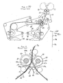
- Fig. 5(a) is a general structural view of a folding machine in a rotary press in the prior art;
- Fig. 5(b) is a schematic view showing a series of cut folded sheets;
- Fig. 6 is an enlarged front view of a distributor section D in Fig. 5(a); and
- Fig. 7 is a side view of the distributor section D in Fig. 6.
- In the following, the present invention will be described with reference to Figs. 1 to 4 of the accompanying drawings. As will be seen from these figures, a web W twice-folded by means of a triangular plate (not shown) is cut into a preset length by
cutter drums 10 and 11 after it has entered between a pair offirst conveyor belts first conveyor belts guide belts rolls guide belts rolls 47b and 59b, and within the diverging routes of the guide belts is disposed atriangular guide 26 with one apex of the triangle placed on the above-mentioned central running positions and directed to the upstream side. The sheet SA distributed to one direction at the distributor section D passes through the path between oneguide surface 26a and theguide belt 14 and is sent to between a pair ofsecond conveyor belts other guide surface 26b and theguide belt 15 and is sent to between a pair ofsecond conveyor belts second conveyor belts second conveyor belts paper sheet runner 22 onto an ejectedpaper sheet conveyor 24 and then sent to one collecting station, and likewise the sheet SB is discharged via an ejectedpaper sheet runner 23 onto an ejectedpaper sheet conveyor 25 and then sent to another collecting station. - Now, the distributor section D consists of a pair of
distributor belts rolls rolls 41a and 42a and therolls rolls rolls 44b and 45b for guiding a pair ofguide belts distributor belt 16 between therolls distributor belt 17 between therolls distributor belts thick parts 16a and 17a and thin parts 16b and 17b along the belt length, and they revolve synchronously so that thethick part 16a and the thin part 17b, and the thin part 16b and the thick part 17a may mesh with each other with the sheets SB and SA, respectively, pinched therebetween in the above-mentioned parallel running section. As a matter of course, these uneven portions of thedistributor belts - When the sheets SA and SB have been fed to the distributor section D constructed as described above, at first the sheet SA is pinched between the thin part 16b and the thick part 17a of the
distributor belts distributor belt 16, and therefore, it advances into the gap between oneguide surface 26a (on the side of the distributor belt 16) of thetriangular guide 26 having its upstream side apex placed at the above-mentioned central running position, and oneguide belt 14 guided in a diverging manner. The next succeeding sheet SB is now pinched between thethick part 16a and the thin part 17b of thedistributor belts distributor belt 17, and therefore, it advances into the gap between theother guide surface 26b (on the side of the distributor belt 17) of thetriangular guide 26 and theother guide belt 15. In this way, for the sheets being fed continuously to the distributor section D, the alternate distributing operations as described above in connection to the sheets SA and SB are repeated. - In addition, as shown in Fig. 3, the distributor belt 16 (17) in the distributor section D is disposed so as to pinch the opposite edge portions of a sheet like the first conveyor belt 12 (13) at the upper stream and the
second conveyor belts 18 and 20 (19 and 21) at the lower stream, and thereby unstable behaviors of the opposite edge portions of a sheet during high speed conveyance can be prevented. - Furthermore, since the pair of
first conveyor belts distributor belts second conveyor belts first conveyor belts distributor belts first conveyor belts distributor belts triangular guide 26 is designed to be a triangular guide provided withnozzle holes nozzle holes guide surfaces guide surfaces - In order that the gap distance of the sheet pinching portions of the
first conveyor belts second conveyor belts guide belts - It is to be noted that while the guide belts 14 and 15 running nearly at the same speed as the
distributor belts guide belts first conveyor belts distributor belts guide surfaces triangular guide 26 between thedistributor belts second conveyor belts - As described in detail above, in the folding machine in a rotary press according to the present invention, since the conveyor means for the sheets extending from the cutter drums to the ejected paper sheet runners is composed of first conveyor belts, distributor belts, the second conveyor belts and guide belts (or fixed guide members), a waving condition of the sheet generated in the flow direction of the sheet can be eliminated by selecting the conveying speed on the downstream side a little faster than that on the upstream side, also by forming a flat portion having a length equal to the sheet length at the sheet pinching portion by means of the distributor belts, the sheet can be sufficiently pinched by the distributor belts, hence even in the case of thin paper sheets or small-sized sheets the fear of waving, scratching, creasing and paper blocking can be eliminated, and further, since the opposite edge portions of the sheet which present the most unstable behavior during conveyance are pinched except for the guide belts, the fear of the sheet edge portions being folded would disappear.
- While a principle of the present invention has been described above in connection to one preferred embodiment of the invention, it is a matter of course that many apparently widely different embodiments of the present invention could be made without departing from the spirit of the present invention.
Claims (2)
Applications Claiming Priority (2)
| Application Number | Priority Date | Filing Date | Title |
|---|---|---|---|
| JP284766/87 | 1987-11-11 | ||
| JP62284766A JP2511075B2 (en) | 1987-11-11 | 1987-11-11 | Folding machine for rotary printing press |
Publications (3)
| Publication Number | Publication Date |
|---|---|
| EP0315932A2 true EP0315932A2 (en) | 1989-05-17 |
| EP0315932A3 EP0315932A3 (en) | 1990-07-11 |
| EP0315932B1 EP0315932B1 (en) | 1993-03-17 |
Family
ID=17682733
Family Applications (1)
| Application Number | Title | Priority Date | Filing Date |
|---|---|---|---|
| EP88118524A Expired - Lifetime EP0315932B1 (en) | 1987-11-11 | 1988-11-07 | Folding machine in a rotary press |
Country Status (4)
| Country | Link |
|---|---|
| US (1) | US4948112A (en) |
| EP (1) | EP0315932B1 (en) |
| JP (1) | JP2511075B2 (en) |
| DE (1) | DE3879385T2 (en) |
Cited By (9)
| Publication number | Priority date | Publication date | Assignee | Title |
|---|---|---|---|---|
| EP0900755A2 (en) * | 1997-09-05 | 1999-03-10 | Ncr International Inc. | Document transport apparatus |
| US6019714A (en) * | 1995-12-27 | 2000-02-01 | Koenig & Bauer Aktiengesellschaft | Folding apparatus with signature divider |
| FR2788045A1 (en) * | 1998-12-30 | 2000-07-07 | Quad Tech | APPARATUS FOR SLOWING DOWN AND GUIDING A NOTEBOOK AND MANUFACTURING METHOD THEREOF |
| EP1097892A2 (en) * | 1999-11-08 | 2001-05-09 | Heidelberger Druckmaschinen Aktiengesellschaft | Device for and method of cutting and deviating signatures |
| WO2001062641A1 (en) * | 2000-02-21 | 2001-08-30 | Christian Bay | Folding machine for paper sheets comprising a stacking device for the folded sheets |
| US6544160B1 (en) * | 1998-03-13 | 2003-04-08 | Koenig & Bauer Aktiengesellschaft | Former |
| DE19653537B4 (en) * | 1996-02-16 | 2004-11-04 | Heidelberger Druckmaschinen Ag | Device for deflecting a signature in a folder |
| EP2280890A1 (en) * | 2008-05-23 | 2011-02-09 | Goss International Americas, Inc. | A method and device for a combined signature diverter and slowdown device |
| EP3093244B1 (en) | 2015-05-13 | 2018-03-21 | Bizerba SE & Co. KG | Film transport device for a packaging machine |
Families Citing this family (17)
| Publication number | Priority date | Publication date | Assignee | Title |
|---|---|---|---|---|
| JPH0477549U (en) * | 1990-11-21 | 1992-07-07 | ||
| US5490666A (en) * | 1994-08-29 | 1996-02-13 | Heidelberger Druchemaschiner Ag | Folder with spring-biased exit roller |
| US5615878A (en) * | 1995-08-15 | 1997-04-01 | Heidelberg Harris Inc. | Method and apparatus for accelerating and diverting flat products |
| US5702100A (en) * | 1996-03-25 | 1997-12-30 | Heidelberg Harris | Mechanism for diverting signatures by the rotation of surfaces |
| US6116595A (en) * | 1998-04-13 | 2000-09-12 | Quad/Graphics, Inc. | Sheet diverter wedge including air discharge ports |
| JP2000007210A (en) * | 1998-06-23 | 2000-01-11 | Horizon International Kk | Sheet stacking device |
| US6302392B1 (en) | 1998-12-29 | 2001-10-16 | Quad/Tech, Inc. | Sheet diverter for collating signatures and a method thereof |
| US6244593B1 (en) | 1999-08-11 | 2001-06-12 | Quad/Tech, Inc. | Sheet diverter with non-uniform drive for signature collation and method thereof |
| US6832886B2 (en) | 2001-07-27 | 2004-12-21 | C. G. Bretting Manufacturing Co., Inc. | Apparatus and method for stacking sheets discharged from a starwheel assembly |
| US6672209B1 (en) * | 2002-08-06 | 2004-01-06 | Heidelberger Druckmaschinen Ag | Method for magnetically tucking a printing plate into a plate cylinder |
| US6796552B2 (en) | 2002-09-17 | 2004-09-28 | Heidelberger Druckmaschinen Ag | Signature delivery device and method |
| US6877740B2 (en) | 2003-07-30 | 2005-04-12 | C.G. Bretting Manufacturing Company, Inc. | Starwheel feed apparatus and method |
| US7044902B2 (en) * | 2003-12-09 | 2006-05-16 | Quad/Tech, Inc. | Printing press folder and folder components |
| WO2005056451A1 (en) * | 2003-12-12 | 2005-06-23 | Mitsubishi Heavy Industries, Ltd. | Folder for rotary press |
| US7980543B2 (en) * | 2007-08-10 | 2011-07-19 | Goss International Americas, Inc. | Printing press folder with parallel process transport tapes |
| US20130047875A1 (en) * | 2011-08-24 | 2013-02-28 | Goss International Americas, Inc. | Variable signature indexing device |
| US20140121091A1 (en) * | 2012-10-26 | 2014-05-01 | Kabushiki Kaisha Tokyo Kikai Seisakusho | Variable cutoff folding device and printer comprising variable cutoff folding device |
Citations (5)
| Publication number | Priority date | Publication date | Assignee | Title |
|---|---|---|---|---|
| GB549067A (en) * | 1941-09-01 | 1942-11-04 | Igranic Electric Co Ltd | Improvements in or relating to newspaper conveyors |
| CH267407A (en) * | 1946-09-19 | 1950-03-31 | R Hoe & Company Limited | Distributor device. |
| GB1010733A (en) * | 1961-11-22 | 1965-11-24 | Alfred Windmoller | Improved double depositing means for the imbricated depositing of sections severed from a material web |
| GB1311483A (en) * | 1969-08-22 | 1973-03-28 | Surbrook L M | Folders for printing presses |
| EP0169489A1 (en) * | 1984-07-26 | 1986-01-29 | M.A.N.-ROLAND Druckmaschinen Aktiengesellschaft | Device for folding and processing prints |
Family Cites Families (9)
| Publication number | Priority date | Publication date | Assignee | Title |
|---|---|---|---|---|
| GB1541562A (en) * | 1975-03-08 | 1979-03-07 | Timsons Ltd | Method of and apparatus for the handling of sheet material |
| JPS54154622A (en) * | 1978-05-26 | 1979-12-05 | Toshiba Mach Co Ltd | Paper folding apparatus for rotary press |
| DE3030706C2 (en) * | 1980-08-14 | 1983-11-24 | Albert-Frankenthal Ag, 6710 Frankenthal | Folder |
| US4373713A (en) * | 1980-12-24 | 1983-02-15 | Motter Printing Press Co. | Diverter mechanism |
| DE3210203C1 (en) * | 1982-03-19 | 1983-12-15 | M.A.N.- Roland Druckmaschinen AG, 6050 Offenbach | Device for dividing a stream of printed copies |
| US4534552A (en) * | 1983-07-20 | 1985-08-13 | Motter Printing Press Co. | Sheet diverting system |
| DE3527710A1 (en) * | 1985-08-02 | 1987-02-12 | Roland Man Druckmasch | FOLDING APPARATUS FOR CROSS FOLDING PRINTED COPIES |
| DE3534157A1 (en) * | 1985-09-25 | 1987-04-02 | Frankenthal Ag Albert | Folding apparatus |
| US4729282A (en) * | 1986-07-22 | 1988-03-08 | Quad/Tech, Inc. | Sheet diverter for signature collation and method thereof |
-
1987
- 1987-11-11 JP JP62284766A patent/JP2511075B2/en not_active Expired - Lifetime
-
1988
- 1988-11-07 EP EP88118524A patent/EP0315932B1/en not_active Expired - Lifetime
- 1988-11-07 DE DE8888118524T patent/DE3879385T2/en not_active Expired - Lifetime
- 1988-11-09 US US07/268,968 patent/US4948112A/en not_active Expired - Lifetime
Patent Citations (5)
| Publication number | Priority date | Publication date | Assignee | Title |
|---|---|---|---|---|
| GB549067A (en) * | 1941-09-01 | 1942-11-04 | Igranic Electric Co Ltd | Improvements in or relating to newspaper conveyors |
| CH267407A (en) * | 1946-09-19 | 1950-03-31 | R Hoe & Company Limited | Distributor device. |
| GB1010733A (en) * | 1961-11-22 | 1965-11-24 | Alfred Windmoller | Improved double depositing means for the imbricated depositing of sections severed from a material web |
| GB1311483A (en) * | 1969-08-22 | 1973-03-28 | Surbrook L M | Folders for printing presses |
| EP0169489A1 (en) * | 1984-07-26 | 1986-01-29 | M.A.N.-ROLAND Druckmaschinen Aktiengesellschaft | Device for folding and processing prints |
Cited By (14)
| Publication number | Priority date | Publication date | Assignee | Title |
|---|---|---|---|---|
| US6019714A (en) * | 1995-12-27 | 2000-02-01 | Koenig & Bauer Aktiengesellschaft | Folding apparatus with signature divider |
| DE19653537B4 (en) * | 1996-02-16 | 2004-11-04 | Heidelberger Druckmaschinen Ag | Device for deflecting a signature in a folder |
| EP0900755A3 (en) * | 1997-09-05 | 1999-06-09 | Ncr International Inc. | Document transport apparatus |
| US6068255A (en) * | 1997-09-05 | 2000-05-30 | Ncr Corporation | Document transport apparatus |
| EP0900755A2 (en) * | 1997-09-05 | 1999-03-10 | Ncr International Inc. | Document transport apparatus |
| US6544160B1 (en) * | 1998-03-13 | 2003-04-08 | Koenig & Bauer Aktiengesellschaft | Former |
| FR2788045A1 (en) * | 1998-12-30 | 2000-07-07 | Quad Tech | APPARATUS FOR SLOWING DOWN AND GUIDING A NOTEBOOK AND MANUFACTURING METHOD THEREOF |
| US6612213B1 (en) | 1999-11-08 | 2003-09-02 | Heidelberger Druckmaschinen Ag | Double-cut lobed belt diverter |
| EP1097892A3 (en) * | 1999-11-08 | 2002-04-03 | Heidelberger Druckmaschinen Aktiengesellschaft | Device for and method of cutting and deviating signatures |
| EP1097892A2 (en) * | 1999-11-08 | 2001-05-09 | Heidelberger Druckmaschinen Aktiengesellschaft | Device for and method of cutting and deviating signatures |
| WO2001062641A1 (en) * | 2000-02-21 | 2001-08-30 | Christian Bay | Folding machine for paper sheets comprising a stacking device for the folded sheets |
| EP2280890A1 (en) * | 2008-05-23 | 2011-02-09 | Goss International Americas, Inc. | A method and device for a combined signature diverter and slowdown device |
| EP2280890A4 (en) * | 2008-05-23 | 2013-04-03 | Goss Int Americas Inc | A method and device for a combined signature diverter and slowdown device |
| EP3093244B1 (en) | 2015-05-13 | 2018-03-21 | Bizerba SE & Co. KG | Film transport device for a packaging machine |
Also Published As
| Publication number | Publication date |
|---|---|
| DE3879385D1 (en) | 1993-04-22 |
| EP0315932B1 (en) | 1993-03-17 |
| JP2511075B2 (en) | 1996-06-26 |
| DE3879385T2 (en) | 1993-06-24 |
| JPH01127558A (en) | 1989-05-19 |
| US4948112A (en) | 1990-08-14 |
| EP0315932A3 (en) | 1990-07-11 |
Similar Documents
| Publication | Publication Date | Title |
|---|---|---|
| EP0315932B1 (en) | Folding machine in a rotary press | |
| EP0054963B1 (en) | Sheet diverter | |
| US4919027A (en) | Sheet diverting and delivery system | |
| US20060229182A1 (en) | Method And Apparatus For Folding Or Separate Bags | |
| JP2901086B2 (en) | Sorting device | |
| JPH1087162A (en) | Folded page feeder for folding device, feeder for leading edge of web material and folded page feed method for folding device | |
| EP0132763B1 (en) | Sheet diverting system | |
| US5615878A (en) | Method and apparatus for accelerating and diverting flat products | |
| US4969640A (en) | Sweet diverting and delivery system | |
| CA1142560A (en) | Web unit handling method and apparatus | |
| US5607146A (en) | Mechanism for diverting of products in a folding apparatus | |
| US4317656A (en) | Article-deflecting switching means for a system of article conveyors | |
| JPH02233465A (en) | Stacker of golded book | |
| JP2000095407A (en) | Direction changing device for section | |
| US4721294A (en) | Device for folding and continuous handling of printed materials | |
| CA1291176C (en) | Sheet diverter and delivery system | |
| JP3207441B2 (en) | Apparatus for splitting signature flow | |
| US4602777A (en) | Sheet feeding apparatus | |
| US7121201B2 (en) | Printing press folder with air knife | |
| US6321902B1 (en) | Method for dividing the flow of signatures | |
| JPS63208468A (en) | Folding machine of circular printing press | |
| US5108086A (en) | Printing press shunt assembly | |
| GB1589595A (en) | Sheet distributor | |
| GB2277924A (en) | Separator/folder bag machine | |
| JP2003118930A (en) | Method and apparatus for discharging paper from folding machine |
Legal Events
| Date | Code | Title | Description |
|---|---|---|---|
| PUAI | Public reference made under article 153(3) epc to a published international application that has entered the european phase |
Free format text: ORIGINAL CODE: 0009012 |
|
| 17P | Request for examination filed |
Effective date: 19881202 |
|
| AK | Designated contracting states |
Kind code of ref document: A2 Designated state(s): DE FR GB |
|
| PUAL | Search report despatched |
Free format text: ORIGINAL CODE: 0009013 |
|
| AK | Designated contracting states |
Kind code of ref document: A3 Designated state(s): DE FR GB |
|
| 17Q | First examination report despatched |
Effective date: 19920320 |
|
| GRAA | (expected) grant |
Free format text: ORIGINAL CODE: 0009210 |
|
| AK | Designated contracting states |
Kind code of ref document: B1 Designated state(s): DE FR GB |
|
| REF | Corresponds to: |
Ref document number: 3879385 Country of ref document: DE Date of ref document: 19930422 |
|
| ET | Fr: translation filed | ||
| PLBE | No opposition filed within time limit |
Free format text: ORIGINAL CODE: 0009261 |
|
| STAA | Information on the status of an ep patent application or granted ep patent |
Free format text: STATUS: NO OPPOSITION FILED WITHIN TIME LIMIT |
|
| 26N | No opposition filed | ||
| PGFP | Annual fee paid to national office [announced via postgrant information from national office to epo] |
Ref country code: GB Payment date: 19961029 Year of fee payment: 9 |
|
| PGFP | Annual fee paid to national office [announced via postgrant information from national office to epo] |
Ref country code: FR Payment date: 19961111 Year of fee payment: 9 |
|
| PG25 | Lapsed in a contracting state [announced via postgrant information from national office to epo] |
Ref country code: GB Free format text: LAPSE BECAUSE OF NON-PAYMENT OF DUE FEES Effective date: 19971107 |
|
| PG25 | Lapsed in a contracting state [announced via postgrant information from national office to epo] |
Ref country code: FR Free format text: THE PATENT HAS BEEN ANNULLED BY A DECISION OF A NATIONAL AUTHORITY Effective date: 19971130 |
|
| GBPC | Gb: european patent ceased through non-payment of renewal fee |
Effective date: 19971107 |
|
| REG | Reference to a national code |
Ref country code: FR Ref legal event code: ST |
|
| PGFP | Annual fee paid to national office [announced via postgrant information from national office to epo] |
Ref country code: DE Payment date: 20071101 Year of fee payment: 20 |