EP0315558B1 - Electrified sliding rail for a mobile electrical socket - Google Patents
Electrified sliding rail for a mobile electrical socket Download PDFInfo
- Publication number
- EP0315558B1 EP0315558B1 EP88480061A EP88480061A EP0315558B1 EP 0315558 B1 EP0315558 B1 EP 0315558B1 EP 88480061 A EP88480061 A EP 88480061A EP 88480061 A EP88480061 A EP 88480061A EP 0315558 B1 EP0315558 B1 EP 0315558B1
- Authority
- EP
- European Patent Office
- Prior art keywords
- sliding rail
- section
- electrical socket
- profile
- socket
- Prior art date
- Legal status (The legal status is an assumption and is not a legal conclusion. Google has not performed a legal analysis and makes no representation as to the accuracy of the status listed.)
- Expired - Lifetime
Links
Images

Classifications
-
- H—ELECTRICITY
- H01—ELECTRIC ELEMENTS
- H01R—ELECTRICALLY-CONDUCTIVE CONNECTIONS; STRUCTURAL ASSOCIATIONS OF A PLURALITY OF MUTUALLY-INSULATED ELECTRICAL CONNECTING ELEMENTS; COUPLING DEVICES; CURRENT COLLECTORS
- H01R25/00—Coupling parts adapted for simultaneous co-operation with two or more identical counterparts, e.g. for distributing energy to two or more circuits
- H01R25/14—Rails or bus-bars constructed so that the counterparts can be connected thereto at any point along their length
Definitions
- the invention relates to an electrified rod acting as a slide for a mobile electrical outlet.
- the mobile socket is a female socket.
- the present invention relates to an electrified rod of an unconventional model, made of rigid plastic serving as a slide for mobile sockets adapted to this rod.
- the electrical outlet consists of a rail of insulating material 1 which comprises two longitudinal internal housings containing two electrical conductors.
- the plug can slide in the longitudinal direction of the rail.
- This patent describes a low voltage electrical installation which comprises an elongated support having two longitudinal conductors isolated from one another, intended to supply, by means of at least one contact piece, at least one electrical device, said contact part being movable longitudinally on the support.
- Said elongated support is a cornice having two visible longitudinal electrical conductors.
- the contact piece is attached to the support and has two contacts pressing the two conductors of the support. These two contacts are electrically connected to a socket.
- the rod according to the invention has the following advantages over the devices forming the state of the art and in particular over the patent FR-A-2 507 400.
- the wand proposed below has the advantages over the latter following: It is extremely simple in design: no spring, no moving part. The movement along the rod is done using a plastic screw which can be tightened or loosened using a coin. Its dimensions are minimal: for example, 30 millimeters. It is not necessary to dig the wall to install it. The cover that conceals the wand can be incorporated into the decoration. Any handyman can install it. It encompasses the entire perimeter of the room thanks to a system of corners and fittings.
- each lever comprises a conductive branch or branch made of insulating material, the free ends of the conductive blades projecting through the openings of the housing while the free ends of the insulating branches protrude through other openings.
- a complementary profile acting as a cover, can be fitted onto the profile at the level of the head of the T by an opening made on one of the long sides of the rectangular profile serving as a cover.
- the rod At the head of the T and this, on its outer face, the rod has a concave shape to facilitate the establishment of the fixing means.
- the rod can receive one or more female mobile sockets which can hang on said profile at the level of the head of the T by the branches of the T, a fixing means ensures the fixing of said taken on the profile at the head of the T and the contact between the conductive blades of the profile and the contact pads of said movable socket.
- the elements of the rod are connected by connectors whose profile is in all points similar to the T-profile of the rod except its length, for example 50 millimeters; under each conductive metal blade of the connecting profile, a housing is provided which makes it possible to accommodate the ends of the metal blades which are in the profiles of the rods and which are simply stripped and inserted into said housings: a fixing means makes it possible to fix the conductive blades in their respective housing of the connection profile where they are brought into contact with the blades of the connection profile.
- the socket has a rectangular profile with an opening on one of the long sides of the rectangular profile to allow the passage of the foot of the T-shaped profile; the plug is introduced on the T-shaped strip by one end thereof; it comprises an isolated fixing means which is a rigid plastic screw which fixes the socket on the rod and ensures electrical continuity between the contacts; on its external lateral face, the socket has two holes which correspond to the plugs of a male socket; these holes act as conductive sockets, their ends are connected to contact pads which are arranged at the internal face of the tabs which come opposite the conductive strips of the T-rod on which said socket is mounted; due to the plastic material, the legs are flexible enough so that the action of the clamping screw of the socket comes, by tightening on the rod, not only fixing the socket on its support, but also ensuring the electrical contact between the plugs of the socket and the conductive strips of the rod.
- the sockets can thus be short-circuited in particular for security reasons, which avoids, for example, socket covers.
- right angle rod elements are provided, they have the same profile as the straight rod elements.
- the rod is connected to the mains or to a power source by means of a connection profile where the supply wires are introduced into the housing of the connection and fixed by screws.
- Figure 1 is a sectional view of the rod with a movable socket placed on the support profile that is the rod.
- Figure 2 is a plan view of the socket, placed on the rod.
- Figure 3 is a sectional view of the baguette profile.
- Figure 4 is a sectional view of the rod covered by its hidden profile.
- Figure 5 is a sectional view of the connecting profile.
- Figure 6 is a plan view of several rod elements assembled together by fittings and where, part of the rod, is covered by a cover.
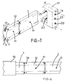
- Figure 7 is a perspective view showing elements of rod profiles and a movable socket.
- the rod 1, according to the invention, is formed by a T-shaped profile, the foot 2 of which is fixed against the wall 3 and the branches 4, 7 of the T of which are found parallel to the plane of the support, wall, ceiling, etc.
- the branches 4, 7 On the internal face of these two branches 4, 7 is joined, on each, a conductive strip 5 and 6.
- the rod 1 can have a concave shape, so as to facilitate the installation of fixing means 8 for the rod on its support.
- a hole which makes it possible to introduce a concrete nail 8 which makes it possible to fix the strip 1 to the wall 3.
- the section of the conductive strips 5, 6 can be 2.5 mm2.
- a means serving as a plastic rim 9 serves as an insulator and prevents the conductive blades 5, 6 from being touched by manipulating the strip.
- another complementary profile acts as a cover 10 and comes to face on the head of the T-profile by an opening 11 made on one of the long sides of the rectangular profile making cache office 10.
- the strip 1, formed by the T-shaped section, is made up of elements, for example one meter long and which can optionally be cut on demand.
- connectors 12 In order to connect two rod elements together, there are connectors 12. Said connectors 12 are in all points similar to the profile of the rod 1 except their length, for example, fifty millimeters long. Under the conductive metal blade 13 or 14 disposed under each branch of the connector 12, there is provided a housing 15 which accommodates the ends of the metal blades 5, 6 which are in the profiles of the rods 1 and which suffices to strip material 9 from the profile 2. To connect, it is necessary to cut the T-profile in 2, perpendicular to its longitudinal axis, then cutting the plastic material 9 so as to leave bare the conductors 5 and 6. The ends of these blades 5, 6 are introduced into the housings 15 of the connector 12.
- An insulated fixing means 16 allows the conductive blades 5, 6 to be fixed in their respective housing 15 of the connection profile 12 where they are brought into contact with the blades 13, 14 of the connection profile 12.
- This means can be a plastic head screw 16 which, screwed, used to clamp the fitting blades against the ends to be connected with strip blades.
- This socket 17 uses the strip 1 like a rail. It is introduced on the rod 1 at a connector 12.
- the socket 17 therefore has a profile similar to that of the cover 10, that is to say rectangular with an opening 18 on one of the long sides of the rectangular profile for allow the passage of the foot 2 of the T.
- the socket 17 is introduced on the rod by one end thereof. It comprises an isolated fixing means 23 which is a rigid plastic screw 23 which fixes the socket 17 on the rod 1 and ensures electrical continuity between the contacts.
- the socket 17 On its external lateral face, the socket 17 has two holes 19, 20 which correspond to the plugs of a male socket. These holes 19, 20 act as conductive sockets, they are therefore conductive, their end is connected to contact pads 21, 22 which are arranged at the internal face of the legs which come opposite the conductive blades 5, 6 of the rod 1 in T on which said socket 17 is mounted.
- the action of the tightening screw 23 of the socket 17 comes, by tightening on the rod 1, to fix the socket 17 on its support, but also ensures the electrical contact between the studs 21, 22 of the socket 17 and the blades conductors 5, 6 of the rod 1.
- the profile, fitting and mobile socket must not be made of excessively flexible plastic.
- the cover must be made of flexible plastic: to be able to adapt to the profile. To remove the cover, it is necessary to press in the center of the strip (which is possible, since there is a hollowed out part on the profile) and at the same time release the upper and lower parts of the opening 2.
- the proposed rod and mobile plug are designed so that they can be hidden in the decor.
- the cache could present a decoration (reminding, for example, the friezes of the wallpaper or the color of the plinths).
Abstract
Description
L'invention a pour objet une baguette électrifiée faisant office de glissière pour une prise électrique mobile. Selon un mode de réalisation préféré la prise mobile est une prise femelle.The invention relates to an electrified rod acting as a slide for a mobile electrical outlet. According to a preferred embodiment, the mobile socket is a female socket.
La présente invention concerne une baguette électrifiée d'un modèle non conventionnel, en plastique rigide servant de glissière à des prises mobiles adaptées à cette baguette.The present invention relates to an electrified rod of an unconventional model, made of rigid plastic serving as a slide for mobile sockets adapted to this rod.
Traditionnellement, les prises femelles sont fixes, et l'usager doit avoir recours à des prises multiples et à des rallonges, ce qui entraîne l'utilisation de fils volants traversant les pièces habitables. Ces fils sont à la fois inesthétiques et dangereux.Traditionally, the female sockets are fixed, and the user must have recourse to multiple sockets and extensions, which involves the use of flying wires crossing the habitable rooms. These threads are both unsightly and dangerous.
L'état de la technique peut être défini notamment par le brevet FR-A-2 507 400, qui est l'équivalent du brevet EP-A-0066559.The state of the art can be defined in particular by patent FR-A-2,507,400, which is the equivalent of patent EP-A-0066559.
La prise électrique consiste en un rail en matière isolante 1 qui comporte deux logements internes longitudinaux renfermant deux conducteurs électriques . Une ouverture longitudinale 6, formée dans une face du rail, reçoit une fiche électrique associée qui consiste en un boitier 9 muni de branches conductrices en saillie qui viennent en contact avec les conducteurs électriques respectifs. La fiche peut coulisser dans la direction longitudinale du rail.The electrical outlet consists of a rail of insulating
L'état de la technique peut être défini notamment par le brevet CH-A-325.635.The state of the art can be defined in particular by patent CH-A-325,635.
Ce brevet décrit une installation électrique basse tension qui comprend un support allongé présentant deux conducteurs longitudinaux isolés l'un de l'autre, destinés à alimenter, par l'intermédiaire d'au moins une pièce de contact, au moins un appareil électrique, ladite pièce de contact étant mobile longitudinalement sur le support. Ledit support allongé est une corniche présentant deux conducteurs électriques longitudinaux apparents. La pièce de contact est accrochée au support et présente deux contacts pressant les deux conducteurs du support. Ces deux contacts sont reliés électriquement à une douille.This patent describes a low voltage electrical installation which comprises an elongated support having two longitudinal conductors isolated from one another, intended to supply, by means of at least one contact piece, at least one electrical device, said contact part being movable longitudinally on the support. Said elongated support is a cornice having two visible longitudinal electrical conductors. The contact piece is attached to the support and has two contacts pressing the two conductors of the support. These two contacts are electrically connected to a socket.
La baguette, selon l'invention, présente les avantages suivants sur les dispositifs formant l'état de la technique et notamment sur le brevet FR-A-2 507 400.The rod according to the invention has the following advantages over the devices forming the state of the art and in particular over the patent FR-A-2 507 400.
La baguette proposée ci-après présente sur ce dernier les avantages suivants :
Elle est extrêmement simple de conception : pas de ressort, pas de pièce mobile. Le déplacement le long de la baguette se fait à l'aide d'une vis de plastique qui peut-être serrée ou desserrée à l'aide d'une pièce de monnaie. Son encombrement est minimal : par exemple, 30 millimètres. Il n'est pas nécessaire de creuser le mur pour la poser. Le cache qui dissimule la baguette peut s'incorporer à la décoration. N'importe quel bricoleur peut la mettre en place. Elle englobe tout le périmètre de la pièce grâce à un système de coins et de raccords.The wand proposed below has the advantages over the latter following:
It is extremely simple in design: no spring, no moving part. The movement along the rod is done using a plastic screw which can be tightened or loosened using a coin. Its dimensions are minimal: for example, 30 millimeters. It is not necessary to dig the wall to install it. The cover that conceals the wand can be incorporated into the decoration. Any handyman can install it. It encompasses the entire perimeter of the room thanks to a system of corners and fittings.
Au contraire, la baguette décrite dans le brevet N°2 507 400 décrit des leviers coudés, des ressorts interposés entre le boitier et les leviers coudés, chaque levier comprend une branche conductrice ou branche en matière isolante, les libres extrémités des lames conductrices faisant saillie par les ouvertures du boitier tandis que les extrémités libres des branches isolantes font saillie par d'autres ouvertures.On the contrary, the rod described in patent No. 2,507,400 describes bent levers, springs interposed between the housing and the bent levers, each lever comprises a conductive branch or branch made of insulating material, the free ends of the conductive blades projecting through the openings of the housing while the free ends of the insulating branches protrude through other openings.
Ces différentes pièces mécaniques sont la source de panne et augmentent trop le coût de fabrication.These different mechanical parts are the source of failure and increase the manufacturing cost too much.
La baguette électrifiée selon l'invention fait office de glissière pour une prise amovible, ladite baguette, en matière isolée, comporte au moins deux lames conductrices qui peuvent venir en contact avec des élements conducteurs issus d'une prise amovible qui vient, après introduction, dans la glissière pour y être fixée à l'endroit choisi par l'utilisateur, ladite baguette comporte également des trous pour permettre le passage des moyens de fixation pour fixer ladite baguette sur son support ; elle est constituée :
- par un profilé en T qui fait office de glissière dont le pied est fixé contre le support et dont les branches du T sont parallèles au plan du support, lesdites lames conductrices sont accolées chacune sur la face interne des branches, du profilé en T ;
- par des profilés complémentaires du T qui peuvent être emboités sur ladite glissière du profilé en T et qui font office de cache ou de prise ou de raccord.
- by a T-shaped profile which acts as a slide, the foot of which is fixed against the support and the branches of the T of which are parallel to the plane of the support, said conductive strips are joined together on the internal face of the branches of the T-shaped section;
- by complementary profiles of the T which can be fitted onto said slide of the T profile and which act as a cover or socket or connector.
Un profilé complémentaire, faisant office de cache, peut être emboité sur le profilé au niveau de la tête du T par une ouverture pratiquée sur un des grands côtés du profilé rectangulaire faisant office de cache.A complementary profile, acting as a cover, can be fitted onto the profile at the level of the head of the T by an opening made on one of the long sides of the rectangular profile serving as a cover.
Au niveau de la tête du T et ce, sur sa face extérieure, la baguette a une forme concave pour faciliter la mise en place des moyens de fixation.At the head of the T and this, on its outer face, the rod has a concave shape to facilitate the establishment of the fixing means.
La baguette peut recevoir une ou plusieurs prises mobiles femelles qui peuvent venir s'accrocher sur ledit profilé au niveau de la tête du T par les branches du T, un moyen de fixation assure la fixation de ladite prise sur le profilé au niveau de la tête du T et le contact entre les lames conductrices du profilé et les plots de contact de ladite prise mobile.The rod can receive one or more female mobile sockets which can hang on said profile at the level of the head of the T by the branches of the T, a fixing means ensures the fixing of said taken on the profile at the head of the T and the contact between the conductive blades of the profile and the contact pads of said movable socket.
Les éléments de baguette sont raccordés par des raccords dont le profilé est en tous points analogue au profilé en T de la baguette si ce n'est sa longueur, par example 50 millimètres ; sous chaque lame métallique conductrice du profilé raccord, est prévu un logement qui permet de loger les extrémités des lames métalliques qui sont dans les profilés des baguettes et qui sont simplement dénudées et introduites dans lesdits logements : un moyen de fixation permet de fixer les lames conductrices dans leur logement respectif du profilé raccord où elles sont mises en contact avec les lames du profilé raccord.The elements of the rod are connected by connectors whose profile is in all points similar to the T-profile of the rod except its length, for example 50 millimeters; under each conductive metal blade of the connecting profile, a housing is provided which makes it possible to accommodate the ends of the metal blades which are in the profiles of the rods and which are simply stripped and inserted into said housings: a fixing means makes it possible to fix the conductive blades in their respective housing of the connection profile where they are brought into contact with the blades of the connection profile.
La prise a un profilé rectangulaire avec une ouverture sur un des grands côtés du profilé rectangulaire pour permettre le passage du pied du profilé en forme de T ; la prise s'introduit sur la baguette profilée en T par une extrémité de celle-ci ; elle comporte un moyen de fixation isolé qui est une vis en plastique rigide qui fixe la prise sur la baguette et assure la continuité électrique entre les contacts ; sur sa face latérale extérieure, la prise a deux trous qui correspondent aux fiches d'une prise mâle ; ces trous font office de douilles conductrices, leur extrémité est reliée à des plots de contact qui sont disposés au niveau de la face interne des pattes qui viennent en regard des lames conductrices de la baguette en T sur laquelle ladite prise est montée ; du fait de la matière plastique, les pattes sont suffisamment souples pour que l'action de la vis de serrage de la prise vienne, en se serrant sur la baguette, non seulement fixer la prise sur son support, mais également assurer le contact électrique entre les plots de la prise et les lames conductrices de la baguette.The socket has a rectangular profile with an opening on one of the long sides of the rectangular profile to allow the passage of the foot of the T-shaped profile; the plug is introduced on the T-shaped strip by one end thereof; it comprises an isolated fixing means which is a rigid plastic screw which fixes the socket on the rod and ensures electrical continuity between the contacts; on its external lateral face, the socket has two holes which correspond to the plugs of a male socket; these holes act as conductive sockets, their ends are connected to contact pads which are arranged at the internal face of the tabs which come opposite the conductive strips of the T-rod on which said socket is mounted; due to the plastic material, the legs are flexible enough so that the action of the clamping screw of the socket comes, by tightening on the rod, not only fixing the socket on its support, but also ensuring the electrical contact between the plugs of the socket and the conductive strips of the rod.
Par une action de rotation d'un quart de tour sur la vis de la prise, celle-ci peut être mise sous tension ou pas.By a quarter-turn rotation action on the plug screw, it can be energized or not.
Les prises peuvent être ainsi court-circuitées notamment pour des raisons de sécurité, ce qui évite, par exemple, des cache prises.The sockets can thus be short-circuited in particular for security reasons, which avoids, for example, socket covers.
Pour les coins, des éléments de baguette à angle droit sont prévus, ils ont le même profilé que les éléments droits de baguette.For the corners, right angle rod elements are provided, they have the same profile as the straight rod elements.
La baguette est raccordée au secteur ou à une source d'alimentation au moyen d'un profilé raccord où les fils d'alimentation sont introduits dans les logements du raccord et fixés par des vis.The rod is connected to the mains or to a power source by means of a connection profile where the supply wires are introduced into the housing of the connection and fixed by screws.
Les dessins ci-joints sont donnés à titre d'exemples indicatifs et non limitatifs. Ils représentent un mode de réalisation préféré selon l'invention. Ils permettront de comprendre aisément l'invention.The attached drawings are given as indicative and non-limiting examples. They represent a preferred embodiment according to the invention. They will allow the invention to be easily understood.
La figure 1 est une vue en coupe de la baguette avec une prise mobile mise en place sur le profilé support qu'est la baguette.Figure 1 is a sectional view of the rod with a movable socket placed on the support profile that is the rod.
La figure 2 est une vue en plan de la prise, mise en place sur la baguette.Figure 2 is a plan view of the socket, placed on the rod.
La figure 3 est une vue en coupe du profilé baguette.Figure 3 is a sectional view of the baguette profile.
La figure 4 est une vue en coupe de la baguette recouverte par son profilé cache.Figure 4 is a sectional view of the rod covered by its hidden profile.
La figure 5 est une vue en coupe du profilé raccord.Figure 5 is a sectional view of the connecting profile.
La figure 6 est une vue en plan de plusieurs éléments de baguette assemblés entre-eux par des raccords et où, une partie de la baguette, est recouverte par un cache.Figure 6 is a plan view of several rod elements assembled together by fittings and where, part of the rod, is covered by a cover.
La figure 7 est une vue en perpective mettant en évidence des éléments de profilés baguettes et une prise mobile.Figure 7 is a perspective view showing elements of rod profiles and a movable socket.
La baguette 1, selon l'invention, est formée par un profilé en T dont le pied 2 est fixé contre le mur 3 et dont les branches 4, 7 du T se retrouvent parallèles au plan du support, mur, plafond etc. Sur la face interne de ces deux branches 4, 7 est accolée, sur chacune, une lame conductrice 5 et 6. Il y a donc une lame supérieure 5 sur la branche supérieure 4 et une lame inférieure 6 sur la branche inférieure 7.The
Au niveau de la tête du T et ce, sur sa face extérieure, la baguette 1 peut avoir une forme concave et ce, de manière à faciliter la mise en place de moyens de fixation 8 de la baguette sur son support. A différents intervalles au centre de la partie concave est prévu un trou qui permet d'introduire un clou à béton 8 qui permet de fixer la baguette 1 au mur 3.At the head of the T and this, on its outer face, the
La section des lames conductrices 5, 6 peut être de 2,5 mm2. Un moyen faisant office de rebord en plastique 9 sert d'isolant et évite que l'on puisse toucher les lames conductrices 5, 6 en manipulant la baguette.The section of the
De manière à mieux isoler la baguette 1, un autre profilé complémentaire est prévu, il fait office de cache 10 et vient s'emboiter de face sur la tête du profilé en T par une ouverture 11 pratiquée sur un des grands côtés du profilé rectangulaire faisant office de cache 10.In order to better isolate the
La baguette 1, formée par le profilé en T, se présente en éléments par exemple d'un mètre de long et pouvant, éventuellement, être coupés à la demande.The
Afin de raccorder deux éléments de baguette entre eux, il existe des raccords 12. Lesdits raccords 12 sont en tous points analogues au profilé de la baguette 1 exceptée leur longueur, par exemple, cinquante millimètres de long. Sous la lame métallique conductrice 13 ou 14 disposée sous chaque branche du raccord 12, il est prévu un logement 15 qui permet de loger les extrémités des lames métalliques 5, 6 qui sont dans les profilés des baguettes 1 et qu'il suffit de dénuder de la matière 9 du profilé 2.Pour raccorder, il est nécessaire de couper le profilé en 2 en T, perpendiculairement à son axe longitudinal, puis à couper la matière de plastique 9 de façon à laisser à nu les conducteurs 5 et 6. Les extrémités de ces lames 5, 6 sont introduites dans les logements 15 du raccord 12. Un moyen de fixation isolé 16 permet de fixer les lames conductrices 5, 6 dans leur logement 15 respectif du profilé raccord 12 où elles sont mises en contact avec les lames 13, 14 du profilé raccord 12. Ce moyen peut être une vis à tête en plastique 16 qui, vissée, permet de serrer les lames du raccord contre les extrémités à raccorder des lames de baguette.In order to connect two rod elements together, there are
Sur la baguette 1, il est possible de monter une prise mobile femelle 17. Cette prise 17 utilise la baguette 1 comme un rail. Elle est introduite sur la baguette 1 au niveau d'un raccord 12. La prise 17 a donc un profilé voisin de celui du cache 10, c'est-à-dire rectangulaire avec une ouverture 18 sur un des grands côtés du profilé rectangulaire pour permettre le passage du pied 2 du T. La prise 17 s'introduit sur la baguette par une extrémité de celle-ci. Elle comporte un moyen de fixation isolé 23 qui est une vis en plastique rigide 23 qui fixe la prise 17 sur la baguette 1 et assure la continuité électrique entre les contacts. Sur sa face latérale extérieure, la prise 17 a deux trous 19, 20 qui correspondent aux fiches d'une prise mâle. Ces trous 19, 20 font office de douilles conductrices, ils sont donc conducteurs, leur extrémité est reliée à des plots de contact 21, 22 qui sont disposés au niveau de la face interne des pattes qui viennent en regard des lames conductrices 5, 6 de la baguette 1 en T sur laquelle ladite prise 17 est montée.On the
L'action de la vis de serrage 23 de la prise 17 vient, en se serrant sur la baguette 1, fixer la prise 17 sur son support, mais assure également le contact électrique entre les plots 21, 22 de la prise 17 et les lames conductrices 5, 6 de la baguette 1.The action of the tightening
Par une action de rotation d'un quart de tour sur la vis 21 de la prise celle-ci peut être mise sous tension ou pas.By a quarter-turn rotation action on the
Le profilé, le raccord et la prise mobile ne doivent pas être fabriqués en plastique trop souple.The profile, fitting and mobile socket must not be made of excessively flexible plastic.
Le cache doit être en plastique souple : pour pouvoir s'adapter sur le profilé. Pour enlever le cache, il faut appuyer au centre de la baguette (ce qui est possible, puisqu'il y a une partie évidée sur le profilé) et en même temps dégager les parties supérieures et inférieures de l'ouverture 2.The cover must be made of flexible plastic: to be able to adapt to the profile. To remove the cover, it is necessary to press in the center of the strip (which is possible, since there is a hollowed out part on the profile) and at the same time release the upper and lower parts of the
La baguette et la prise mobile proposées sont conçues de telle sorte qu'elles puissent être dissimulées dans le décor. D'où l'idée que le cache puisse présenter une décoration (rappelant, par exemple, les frises du papier peint ou la teinte des plinthes).The proposed rod and mobile plug are designed so that they can be hidden in the decor. Hence the idea that the cache could present a decoration (reminding, for example, the friezes of the wallpaper or the color of the plinths).
- 1.1.
- BaguetteBaguette
- 2.2.
- Pied du TFoot of the T
- 3.3.
- MurWall
- 4.4.
- Branche supérieureUpper branch
- 5.5.
- Lame supérieure du profilé baguette en TUpper blade of the T-shaped strip
- 6.6.
- Lame inférieure du profilé baguette en TLower blade of the T-shaped strip
- 7.7.
- Branche inférieureLower branch
- 8.8.
- Clou à bétonConcrete nail
- 9.9.
- Rebord isolantInsulating flange
- 10.10.
- CacheHidden
- 11.11.
- OuvertureOpening
- 12.12.
- RaccordsFittings
- 13. 14.13. 14.
-
Lames métalliques conductrices du profilé raccord 12Conductive metal blades of
connection profile 12 - 15.15.
- LogementHousing
- 16.16.
- Vis à tête en plastiquePlastic head screws
- 17.17.
- Prise mobileMobile outlet
- 18.18.
- OuvertureOpening
- 19. 20.19. 20.
- Trous de la prise femelleFemale plug holes
- 21. 22.21. 22.
- Plots de contactsContact pads
- 23.23.
- Vis de serrage - Moyen de fixationClamping screw - Fixing means
Claims (6)
- Electrified sliding rail (1) for a mobile electrical socket (17), said sliding rail made of insulated material (1) comprising at least two conducting blades (5) and (6) which can come into contact with conducting elements (21) and (22) of a mobile electrical socket (17) which is slideably mounted on the sliding rail (1) to be fixed thereon at a point chosen by the user, said sliding rail (1) further comprising holes to allow the passage of fixing means for fixing said sliding rail (1) to its support (3), said sliding rail consisting of- a T-section (1) serving as a sliding rail whose base (2) is fixed to the support (3) and in which the arms (4, 7) of the T are parallel with the plane of the support (3), said conducting blades (5, 6) both being mounted on the inner surface of the arms (4, 7) of the T-section (1);- sections (10, 12, 17) complementary to the T, which are fitted on said T-sectioned sliding rail (1) and serve as a cover (10) or as an electrical socket (17) or as a link (12).
- Electrified sliding rail (1) according to claim 1,
characterized in that a complementary section (10), serving as a cover, is fitted on the section (1) at the level of the top of the T by using an opening (11) formed at one of the long sides of the rectangular section which serves as a cover (10). - Electrified sliding rail (1) according to claim 1,
characterized in that the outer surface of the sliding rail is concavely shaped at the level of the top of the T, in order to facilitate installment of the fixing means (8). - Electrified sliding rail (1) according to claim 1,
characterized in that it receives one or more mobile electrical sockets (17) attached to said section at the level of the top of the T (1) by means of the arms (4, 7) of the T, a fixing means (23) ensures the attachment of said electrical socket (17) to the section (1) at the level of the top of the T and the contact between the conducting blades (5, 6) of the section (1) and the conducting elements (21, 22) of the mobile electrical socket (17). - Electrified sliding rail (1) according to claim 4,
characterized in that the electrical socket (17) has a rectangular section with an opening (18) at one of the long sides of the rectangular section to allow the passage of the base (2) of the T-section (1); the electrical socket (17) is slipped on the T-sectioned sliding rail (1) at one end thereof; it comprises an insulated fixing means (23) which is a rigid plastic screw (23) which fixes the electrical socket (17) to the sliding rail (1) and ensures the electrical continuity between the contacts; on its outer lateral face, the electrical socket (17) has two holes (19, 20) corresponding to the pins of a plug; said holes (19, 20) serve as conducting bushes, their ends being connected with contact pieces (21, 22) which are disposed at the level of the inner face of the claws which come to face the conducting blades (5, 6) of the T-sectioned sliding rail (1) on which said electrical socket (17) is mounted; due to the plasticity of the material, the claws are sufficiently flexible so that the action of the fastening screw (23) of the electrical socket (17), when driven into the sliding rail (1), not only fixes the electrical socket (17) to the support thereof but ensures also the electrical contact between the contact pieces (21, 22) of the electrical socket (17) and the conducting blades (5, 6) of the sliding rail (1). - Process for connecting sliding rail elements according to claim 1,
characterized in that the sliding rail elements (1) are connected by means of links (12) whose section corresponds to the T-section of the sliding rail (1) in every respect except for its length, for example fifty millimetres; for each conducting metal blade (13, 14) of the link section (12) a seat (15) is provided which allows to dispose the ends of the metal blades (5, 6) which are located in the sections (2) of the sliding rails (1) and which are simply bared and introduced into said seats (15): a fixing means (16) serves for fixing the conducting blades (5, 6) in their respective seat (15) in the link section (12), where they are brought into contact with the blades (13, 14) of the link section (12).
Priority Applications (1)
| Application Number | Priority Date | Filing Date | Title |
|---|---|---|---|
| AT88480061T ATE87133T1 (en) | 1987-11-04 | 1988-10-24 | ELECTRIFIED SLIDING RAIL FOR A MOVABLE ELECTRICAL SOCKET. |
Applications Claiming Priority (2)
| Application Number | Priority Date | Filing Date | Title |
|---|---|---|---|
| FR8715387A FR2622747B1 (en) | 1987-11-04 | 1987-11-04 | ELECTRIFIED STRIP AS A SLIDE OFFICE FOR A MOBILE ELECTRICAL OUTLET |
| FR8715387 | 1987-11-04 |
Publications (2)
| Publication Number | Publication Date |
|---|---|
| EP0315558A1 EP0315558A1 (en) | 1989-05-10 |
| EP0315558B1 true EP0315558B1 (en) | 1993-03-17 |
Family
ID=9356547
Family Applications (1)
| Application Number | Title | Priority Date | Filing Date |
|---|---|---|---|
| EP88480061A Expired - Lifetime EP0315558B1 (en) | 1987-11-04 | 1988-10-24 | Electrified sliding rail for a mobile electrical socket |
Country Status (4)
| Country | Link |
|---|---|
| EP (1) | EP0315558B1 (en) |
| AT (1) | ATE87133T1 (en) |
| DE (1) | DE3879381T2 (en) |
| FR (1) | FR2622747B1 (en) |
Families Citing this family (4)
| Publication number | Priority date | Publication date | Assignee | Title |
|---|---|---|---|---|
| IL104618A (en) * | 1993-02-04 | 2000-10-31 | Meir Amiram | Contact rail and adapter |
| DE10025648B4 (en) * | 2000-05-24 | 2010-04-08 | Zumtobel Lighting Gmbh | Busbar system |
| FR2889892A1 (en) * | 2005-08-19 | 2007-02-23 | Jerome Fraysse | Electric current routing and delivering device for electric network of building, has electric socket elements having isolating parts assuring isolation of conductor assemblies, where each element slides in tube and is placed along tube |
| FR2972289B1 (en) * | 2011-03-01 | 2013-03-01 | Schneider Electric Ind Sas | CURRENT DRIVER |
Family Cites Families (2)
| Publication number | Priority date | Publication date | Assignee | Title |
|---|---|---|---|---|
| CH325635A (en) * | 1956-02-18 | 1957-11-15 | Buhrer Philippe | Low voltage electrical installation |
| IT1218281B (en) * | 1981-06-03 | 1990-04-12 | Roberto Arena | LINE AND LIGHT POINT |
-
1987
- 1987-11-04 FR FR8715387A patent/FR2622747B1/en not_active Expired - Fee Related
-
1988
- 1988-10-24 AT AT88480061T patent/ATE87133T1/en not_active IP Right Cessation
- 1988-10-24 DE DE8888480061T patent/DE3879381T2/en not_active Expired - Fee Related
- 1988-10-24 EP EP88480061A patent/EP0315558B1/en not_active Expired - Lifetime
Also Published As
| Publication number | Publication date |
|---|---|
| ATE87133T1 (en) | 1993-04-15 |
| FR2622747A1 (en) | 1989-05-05 |
| EP0315558A1 (en) | 1989-05-10 |
| DE3879381D1 (en) | 1993-04-22 |
| DE3879381T2 (en) | 1993-09-16 |
| FR2622747B1 (en) | 1992-03-20 |
Similar Documents
| Publication | Publication Date | Title |
|---|---|---|
| EP0587882B1 (en) | Device for the support and power supply of very low voltage lighting | |
| FR3000312A1 (en) | ELECTRICAL BOX FOR ELECTRICAL EQUIPMENT | |
| EP0683998B1 (en) | Exhibition or display device with means for both attachment and power supply of light sources | |
| EP0868737B1 (en) | Device for connecting an external conductor such as a cable to a contact of an electrical apparatus | |
| EP0315558B1 (en) | Electrified sliding rail for a mobile electrical socket | |
| FR2488064A1 (en) | Mounting box for electric switch - includes extended base covering surface mounted moulded conduit carrying supply wires | |
| EP0669223B1 (en) | Signal light with a plurality of lamps for vehicle | |
| EP0660461B1 (en) | Multiple base for socket | |
| FR2513030A1 (en) | ELECTRICAL DISTRIBUTION DEVICE | |
| EP2068411A1 (en) | Embedded electrical appliance with quick connection | |
| FR2951588A1 (en) | Connection base for electrical connection box mounted on vertical wall of building, has anchoring device anchored on fixation rail and fixed at bottom part of block, and facade part presenting geometry compatible with opening of panel | |
| EP1538718A1 (en) | Mounting claws return mechanism | |
| FR2666479A1 (en) | MOUNTING BOX FOR ELECTRICAL APPLIANCE. | |
| EP1369967A1 (en) | Courant outlet | |
| WO2014096681A1 (en) | Equipment module and electrical connector of electrical equipment | |
| EP1199779B1 (en) | Connector with flexible terminals, in particular for an electrical apparatus and electrical connector comprising such terminals | |
| FR2730355A1 (en) | BUILT-IN ELECTRICAL EQUIPMENT | |
| FR2472286A1 (en) | ADJUSTING ASSEMBLY OF A CONNECTION BLOCK IN A COVER | |
| BE727904A (en) | ||
| FR2825522A1 (en) | Domestic electrical installation ceiling radiating heating panel piercing electrical connection having cable gripping section and tapered section/electrical contacts piercing double sheath isolating section/contacting conductor centres. | |
| EP0292380A1 (en) | Process and device for the electrical connections in localities consisting of several rooms | |
| FR2566196A1 (en) | Rapid-connection socket | |
| FR2591041A3 (en) | Bar with sockets for electrical contacts | |
| FR2597671A1 (en) | Screw socket device having a simplified structure | |
| FR2763754A1 (en) | Improved electrical ducting for electrical apparatus connection |
Legal Events
| Date | Code | Title | Description |
|---|---|---|---|
| PUAI | Public reference made under article 153(3) epc to a published international application that has entered the european phase |
Free format text: ORIGINAL CODE: 0009012 |
|
| AK | Designated contracting states |
Kind code of ref document: A1 Designated state(s): AT BE CH DE ES GB GR IT LI LU NL SE |
|
| 17P | Request for examination filed |
Effective date: 19890529 |
|
| 17Q | First examination report despatched |
Effective date: 19911219 |
|
| GRAA | (expected) grant |
Free format text: ORIGINAL CODE: 0009210 |
|
| AK | Designated contracting states |
Kind code of ref document: B1 Designated state(s): AT BE CH DE ES GB GR IT LI LU NL SE |
|
| PG25 | Lapsed in a contracting state [announced via postgrant information from national office to epo] |
Ref country code: IT Free format text: LAPSE BECAUSE OF FAILURE TO SUBMIT A TRANSLATION OF THE DESCRIPTION OR TO PAY THE FEE WITHIN THE PRE;WARNING: LAPSES OF ITALIAN PATENTS WITH EFFECTIVE DATE BEFORE 2007 MAY HAVE OCCURRED AT ANY TIME BEFORE 2007. THE CORRECT EFFECTIVE DATE MAY BE DIFFERENT FROM THE ONE RECORDED.SCRIBED TIME-LIMIT Effective date: 19930317 Ref country code: SE Effective date: 19930317 Ref country code: NL Effective date: 19930317 Ref country code: AT Effective date: 19930317 Ref country code: GR Free format text: LAPSE BECAUSE OF FAILURE TO SUBMIT A TRANSLATION OF THE DESCRIPTION OR TO PAY THE FEE WITHIN THE PRESCRIBED TIME-LIMIT Effective date: 19930317 Ref country code: ES Free format text: THE PATENT HAS BEEN ANNULLED BY A DECISION OF A NATIONAL AUTHORITY Effective date: 19930317 |
|
| REF | Corresponds to: |
Ref document number: 87133 Country of ref document: AT Date of ref document: 19930415 Kind code of ref document: T |
|
| REF | Corresponds to: |
Ref document number: 3879381 Country of ref document: DE Date of ref document: 19930422 |
|
| GBT | Gb: translation of ep patent filed (gb section 77(6)(a)/1977) |
Effective date: 19930603 |
|
| NLV1 | Nl: lapsed or annulled due to failure to fulfill the requirements of art. 29p and 29m of the patents act | ||
| PG25 | Lapsed in a contracting state [announced via postgrant information from national office to epo] |
Ref country code: LU Free format text: LAPSE BECAUSE OF NON-PAYMENT OF DUE FEES Effective date: 19931031 Ref country code: LI Effective date: 19931031 Ref country code: BE Effective date: 19931031 Ref country code: CH Effective date: 19931031 |
|
| PLBE | No opposition filed within time limit |
Free format text: ORIGINAL CODE: 0009261 |
|
| STAA | Information on the status of an ep patent application or granted ep patent |
Free format text: STATUS: NO OPPOSITION FILED WITHIN TIME LIMIT |
|
| 26N | No opposition filed | ||
| BERE | Be: lapsed |
Owner name: ALLERS CHRISTIAN Effective date: 19931031 Owner name: SAUDA EPOUSE ALLERS GINETTE Effective date: 19931031 |
|
| REG | Reference to a national code |
Ref country code: CH Ref legal event code: PL |
|
| PGFP | Annual fee paid to national office [announced via postgrant information from national office to epo] |
Ref country code: GB Payment date: 19971015 Year of fee payment: 10 |
|
| PGFP | Annual fee paid to national office [announced via postgrant information from national office to epo] |
Ref country code: DE Payment date: 19971229 Year of fee payment: 10 |
|
| PG25 | Lapsed in a contracting state [announced via postgrant information from national office to epo] |
Ref country code: GB Free format text: LAPSE BECAUSE OF NON-PAYMENT OF DUE FEES Effective date: 19981024 |
|
| GBPC | Gb: european patent ceased through non-payment of renewal fee |
Effective date: 19981024 |
|
| PG25 | Lapsed in a contracting state [announced via postgrant information from national office to epo] |
Ref country code: DE Free format text: LAPSE BECAUSE OF NON-PAYMENT OF DUE FEES Effective date: 19990803 |