EP0315501B1 - Deformable washer, especially allowing to predetermine the minimal clamping force of a nut or a bolt - Google Patents
Deformable washer, especially allowing to predetermine the minimal clamping force of a nut or a bolt Download PDFInfo
- Publication number
- EP0315501B1 EP0315501B1 EP88402575A EP88402575A EP0315501B1 EP 0315501 B1 EP0315501 B1 EP 0315501B1 EP 88402575 A EP88402575 A EP 88402575A EP 88402575 A EP88402575 A EP 88402575A EP 0315501 B1 EP0315501 B1 EP 0315501B1
- Authority
- EP
- European Patent Office
- Prior art keywords
- washer
- nut
- diameter
- countersink
- central bore
- Prior art date
- Legal status (The legal status is an assumption and is not a legal conclusion. Google has not performed a legal analysis and makes no representation as to the accuracy of the status listed.)
- Expired - Lifetime
Links
- 239000007787 solid Substances 0.000 claims 1
- 238000010008 shearing Methods 0.000 description 5
- 238000004519 manufacturing process Methods 0.000 description 3
- 230000000712 assembly Effects 0.000 description 2
- 238000000429 assembly Methods 0.000 description 2
- 239000000463 material Substances 0.000 description 2
- 239000000470 constituent Substances 0.000 description 1
- 238000010276 construction Methods 0.000 description 1
- 230000000694 effects Effects 0.000 description 1
- 230000000284 resting effect Effects 0.000 description 1
- 238000010079 rubber tapping Methods 0.000 description 1
- 238000012795 verification Methods 0.000 description 1
Images

Classifications
-
- F—MECHANICAL ENGINEERING; LIGHTING; HEATING; WEAPONS; BLASTING
- F16—ENGINEERING ELEMENTS AND UNITS; GENERAL MEASURES FOR PRODUCING AND MAINTAINING EFFECTIVE FUNCTIONING OF MACHINES OR INSTALLATIONS; THERMAL INSULATION IN GENERAL
- F16B—DEVICES FOR FASTENING OR SECURING CONSTRUCTIONAL ELEMENTS OR MACHINE PARTS TOGETHER, e.g. NAILS, BOLTS, CIRCLIPS, CLAMPS, CLIPS OR WEDGES; JOINTS OR JOINTING
- F16B43/00—Washers or equivalent devices; Other devices for supporting bolt-heads or nuts
-
- F—MECHANICAL ENGINEERING; LIGHTING; HEATING; WEAPONS; BLASTING
- F16—ENGINEERING ELEMENTS AND UNITS; GENERAL MEASURES FOR PRODUCING AND MAINTAINING EFFECTIVE FUNCTIONING OF MACHINES OR INSTALLATIONS; THERMAL INSULATION IN GENERAL
- F16B—DEVICES FOR FASTENING OR SECURING CONSTRUCTIONAL ELEMENTS OR MACHINE PARTS TOGETHER, e.g. NAILS, BOLTS, CIRCLIPS, CLAMPS, CLIPS OR WEDGES; JOINTS OR JOINTING
- F16B31/00—Screwed connections specially modified in view of tensile load; Break-bolts
- F16B31/02—Screwed connections specially modified in view of tensile load; Break-bolts for indicating the attainment of a particular tensile load or limiting tensile load
- F16B31/028—Screwed connections specially modified in view of tensile load; Break-bolts for indicating the attainment of a particular tensile load or limiting tensile load with a load-indicating washer or washer assembly
Landscapes
- Engineering & Computer Science (AREA)
- General Engineering & Computer Science (AREA)
- Mechanical Engineering (AREA)
- Bolts, Nuts, And Washers (AREA)
- Clamps And Clips (AREA)
- Springs (AREA)
- Finger-Pressure Massage (AREA)
- Pens And Brushes (AREA)
- Dowels (AREA)
- Force Measurement Appropriate To Specific Purposes (AREA)
- Details Of Spanners, Wrenches, And Screw Drivers And Accessories (AREA)
Abstract
Description
Il est important, notamment dans les fabrications en grandes séries, par exemple dans la construction automobile, d'effectuer le serrage des écrous sur les vis ou des vis dans des trous taraudés avec une force de serrage suffisante. Or, dans ce genre de fabrication, on utilise fréquemment des visseuses motorisées et le couple développé par ce genre de machines dépend de leur réglage; ce couple peut varier assez rapidement au cours de l'emploi, entraînant des variations quelquefois importantes de la force de serrage de la vis ou de l'écrou, et, par conséquent, des pièces à assembler. Si l'opérateur n'effectue pas en temps utile la vérification du serrage, par exemple au moyen d'une clé dynamométrique, il existe un risque que certains assemblages soient insuffisamment serrés.It is important, especially in mass production, for example in automobile construction, to tighten the nuts on the screws or the screws in tapped holes with sufficient clamping force. However, in this type of manufacture, motorized screwdrivers are frequently used and the torque developed by this type of machine depends on their adjustment; this torque can vary quite quickly during use, sometimes resulting in significant variations in the tightening force of the screw or nut, and therefore of the parts to be assembled. If the operator does not carry out the tightening check in good time, for example by means of a torque wrench, there is a risk that certain assemblies are insufficiently tightened.
On a déjà proposé par les US-A-3.306.154 et US-A-3.948.141 des rondelles déformables permettant de vérifier, au moins approximativement, la force de serrage de deux pièces. Cependant la déformation de la rondelle n'est pas entièrement visible après le serrage de sorte qu'il est impossible d'affirmer avec une certitude absolue que la force de serrage est au moins égale à une valeur prédéterminée.US-A-3,306,154 and US-A-3,948,141 have already proposed deformable washers making it possible to check, at least approximately, the clamping force of two parts. However, the deformation of the washer is not entirely visible after tightening, so that it is impossible to state with absolute certainty that the tightening force is at least equal to a predetermined value.
La présente invention a pour objet une rondelle déformable, permettant de prédéterminer une force de serrage minimale d'une vis ou d'un écrou. La déformation prévue de la rondelle n'intervient en effet qu'après le dépassement d'une force prédéterminée par la structure de la rondelle, de sorte que, si la déformation n'est pas visible, on peut en déduire avec certitude que la force minimale n'a pas été atteinte.The present invention relates to a deformable washer, making it possible to predetermine a minimum clamping force of a screw or a nut. The planned deformation of the washer only occurs after the predetermined force has been exceeded by the structure of the washer, so that, if the deformation is not visible, it can be deduced with certainty that the force was not reached.
Une rondelle est constituée, comme il est connu, par une pièce massive, généralement métallique et en forme de disque plan, de faible épaisseur par rapport aux dimensions de sa périphérie et présente un perçage central correspondant sensiblement au diamètre de la vis sur laquelle elle doit être montée.A washer is made up, as is known, by a massive piece, generally metallic and in the form of a flat disc, of small thickness compared to the dimensions of its periphery and has a central bore corresponding substantially to the diameter of the screw on which it must be mounted.
Selon l'invention, la rondelle présente sur l'une de ses faces un lamage circulaire, concentrique au perçage central, dont le diamètre extérieur est notablement supérieur à celui du perçage central. La rondelle comporte, d'autre part, sur sa tranche, dans la région non lamée, une gorge visible, dont le fond cylindrique est également coaxial au perçage central. Ce fond cylindrique présente un diamètre au plus égal au diamètre extérieur du lamage circulaire.According to the invention, the washer present on one of its faces a circular counterbore, concentric with the central bore, the outside diameter of which is considerably greater than that of the central bore. The washer has, on the other hand, on its edge, in the non-lamé region, a visible groove, the cylindrical bottom of which is also coaxial with the central bore. This background cylindrical has a diameter at most equal to the outside diameter of the circular counterbore.
L'invention sera mieux comprise et diverses caractéristiques secondaires ainsi que ses avantages apparaîtront au cours de la description qui va suivre, en référence au dessin annexé, dans lequel:
- La figure 1 est une vue en coupe d'une rondelle déformable selon l'invention, avant et après serrage.
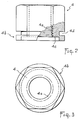
- La figure 2 est une vue en coupe partielle avec arrachement d'un écrou équipé d'une rondelle selon la figure 1 et constituant avec elle une pièce unique.
- La figure 3 est une vue en plan de l'écrou représenté sur la figure 2.
- Figure 1 is a sectional view of a deformable washer according to the invention, before and after tightening.
- Figure 2 is a partial sectional view with cutaway of a nut equipped with a washer according to Figure 1 and constituting with it a single piece.
- FIG. 3 is a plan view of the nut shown in FIG. 2.
Si l'on se reporte à la figure 1, on voit une rondelle désignée par la référence générale 1 constituée, ainsi qu'on le sait, par une pièce plate, par exemple un disque, présentant un perçage central 1a dont le diamètre d est suffisant pour permettre le passage de la tige filetée 2a d'une vis 2 (représentée en trait ponctué) dont la tête 2b peut prendre appui sur la rondelle. La rondelle 1 prend elle-même appui sur une pièce à serrer représentée schématiquement en trait ponctué et désignée par la référence 3.If we refer to Figure 1, we see a washer designated by the
Sur sa face inférieure 1b, c'est-à-dire sur celle qui est en contact avec la pièce à serrer 3, la rondelle 1 présente un lamage circulaire 1c coaxial au perçage 1a. Le diamètre D du lamage est bien évidemment supérieur au diamètre d du perçage 1a et, de préférence, notablement supérieur à celui-ci. Par exemple, dans le cas d'une rondelle circulaire, dont la coupe axiale serait celle qui est représentée sur la figure 1, le diamètre D du lamage sera avantageusement voisin du diamètre moyen de l'anneau que constitue la rondelle. Toutefois, on soulignera dès maintenant et on précisera encore plus loin que la forme de la périphérie extérieure de la rondelle 1 n'est pas imposée par l'invention, bien que la forme d'un disque annulaire soit la plus courante et, en général, la plus avantageuse.On its lower face 1b, that is to say on the one which is in contact with the part to be tightened 3, the
La profondeur p du lamage 1c n'est pas exactement déterminée par l'invention, mais elle sera de préférence voisine de la largeur de l'anneau lamé, c'est-à-dire de la moitié de la largeur de l'anneau constituant la rondelle elle-même.The depth p of the
Sur la tranche de la rondelle 1, dans la région non lamée, il est prévu une gorge 1d dont le fond 1e est cylindrique et coaxial au perçage central 1a ainsi qu'au lamage 1c. Le diamètre D′de ce fond cylindrique est au plus égal au diamètre D du lamage 1c et de préférence très voisin de ce diamètre D. D'autre part, l'épaisseur e de la gorge 1d est elle-même aussi voisine que possible de la profondeur p du lamage. La raison de ces dispositions apparaîtra plus loin.On the edge of the
Bien évidemment, ainsi qu'on le voit sur la figure 1, il subsiste une certaine épaisseur f de matière entre la gorge 1d et le lamage 1c.Obviously, as can be seen in FIG. 1, there remains a certain thickness f of material between the
C'est cette épaisseur f qui permet, comme on va le montrer, de prédéterminer une force de serrage minimale de la vis sur une pièce à serrer ou d'un écrou sur une vis.It is this thickness f which makes it possible, as will be shown, to predetermine a minimum tightening force of the screw on a part to be tightened or of a nut on a screw.
En effet, lorsqu'on tourne la tête 2b de la vis 2, ce qui a pour effet d'écraser la rondelle 1 sur la pièce à serrer 3, la partie supérieure de la rondelle joue le rôle d'un poinçon de cisaillement par rapport à la partie inférieure. La force s'exerçant sur la zone annulaire 1f d'épaisseur f provoquera le cisaillement de cette zone si le couple exercé sur la tête de la vis est suffisant. Dans cette hypothèse, la partie supérieure de la rondelle peut venir coiffer à peu près exactement la partie inférieure (voir figure 1, partie gauche) puisque le fond cylindrique 1e a un diamètre au plus égal à celui du lamage et que l'épaisseur e de la gorge est pratiquement égale à la profondeur p du lamage.Indeed, when the head 2b of the
Dans le cas, visé par la présente invention, où la vis 2 est entraînée par une visseuse motorisée, cette dernière poursuit son mouvement après le cisaillement de la zone 1f de la rondelle. En pratique, le couple de blocage de la visseuse ne peut se dérégler pendant cette dernière phase de l'opération de serrage qui s'effectue généralement sur moins d'un tour de l'arbre de la visseuse et l'on est donc certain, lorsque la rondelle a pris la position représentée sur la partie gauche de la figure 1, qu'elle est serrée avec une force au moins égale à celle nécessaire au cisaillement de la zone 1f.In the case covered by the present invention, where the
A cet égard, on rappellera que la force F nécessaire au cisaillement de la zone 1g est donnée par la formule F = π DfR où D est le diamètre moyen de la zone 1f et f son épaisseur, R étant la résistance du matériau constituant la rondelle. En ce qui concerne la gorge 1d son épaisseur e sera avantageusement comprise entre 0,5 mm et 2 mm, en fonction des dimensions de la rondelle.In this regard, it will be recalled that the force F necessary for the shearing of the area 1 g is given by the formula F = π DfR where D is the mean diameter of the area 1 f and f its thickness, R being the resistance of the constituent material the washer. As regards the
Le lecteur a déjà compris l'intérêt de l'invention pour faciliter le contrôle des fabrications, plus particulièrement du serrage des assemblages de pièces par des vis et/ou des écrous. Si l'on examine en effet l'état de la rondelle, on voit immédiatement la gorge 1d lorsque l'assemblage n'est pas suffisamment serré. Il est alors possible de procéder à un nouveau serrage, en général une vérification au moyen d'une clé dynamométrique. Au contraire, si la gorge 1d a disparu, le contrôleur sait que le serrage est suffisant.The reader has already understood the interest of the invention in facilitating the control of manufacturing, more particularly the tightening of assemblies of parts by screws and / or nuts. If we indeed examine the state of the washer, we immediately see the
D'autre part, le lecteur a également compris que la rondelle selon l'invention peut être placée sous une tête de vis comme dans l'exemple représenté sur la figure 1 ou, au contraire, sous un écrou susceptible d'être monté sur une tige filetée. Il est également évident que le sens de montage de la rondelle est indifférent, le cisaillement de la zone 1f se produisant quelle que soit la face de la rondelle en appui sur la pièce à serrer.On the other hand, the reader has also understood that the washer according to the invention can be placed under a screw head as in the example shown in FIG. 1 or, on the contrary, under a nut capable of being mounted on a threaded shaft. It is also obvious that the mounting direction of the washer is indifferent, the shearing of the area 1 f occurring regardless of the face of the washer resting on the part to be clamped.
On soulignera maintenant que la rondelle selon l'invention peut être facilement incorporée à un écrou, pour ne constituer qu'une seule pièce avec lui. Cette variante de réalisation est représentée aux figures 2 et 3. Si l'on se reporte au dessin, on voit un écrou 4 massif à six pans dont le perçage central 4a est taraudé.It will now be emphasized that the washer according to the invention can be easily incorporated into a nut, so as to constitute only one piece with it. This alternative embodiment is shown in Figures 2 and 3. If Referring to the drawing, there is shown a
La base 4b de l'écrou présente un lamage 4c et une gorge 4d dont les caractéristiques ne seront pas à nouveau décrites car elles correspondent respectivement à celles du lamage 1c et de la gorge 1d décrites en référence à la figure 1.The
On soulignera seulement que le taraudage de l'écrou se prolonge jusqu'au lamage 4c de la base 4b, laquelle peut être constituée par une collerette circulaire, comme on le voit sur les figures, ou au contraire, présenter une forme hexagonale correspondant à celle du corps de l'écrou 4.It will only be emphasized that the tapping of the nut extends up to the countersinking 4 c of the
L'utilisation de l'écrou 4 ainsi que ses avantages sont bien évidemment analogues à ceux qui ont été décrits plus haut, la gorge 4d de la base de l'écrou disparaissant après un serrage suffisant de l'écrou et cisaillement de la zone de raccordement des deux parties constituant la base 4b.The use of the
Claims (5)
Priority Applications (1)
| Application Number | Priority Date | Filing Date | Title |
|---|---|---|---|
| AT88402575T ATE62978T1 (en) | 1987-11-03 | 1988-10-12 | DEFORMABLE WASHER, PARTICULARLY SUITED FOR PREDICTING THE MINIMUM CLAMPING FORCE OF A NUT OR BOLT. |
Applications Claiming Priority (2)
| Application Number | Priority Date | Filing Date | Title |
|---|---|---|---|
| FR8715235A FR2622648B1 (en) | 1987-11-03 | 1987-11-03 | DEFORMABLE WASHER, PARTICULARLY FOR PREDETERMINING THE MINIMUM TIGHTENING FORCE OF A NUT OR A SCREW |
| FR8715235 | 1987-11-03 |
Publications (2)
| Publication Number | Publication Date |
|---|---|
| EP0315501A1 EP0315501A1 (en) | 1989-05-10 |
| EP0315501B1 true EP0315501B1 (en) | 1991-04-24 |
Family
ID=9356442
Family Applications (1)
| Application Number | Title | Priority Date | Filing Date |
|---|---|---|---|
| EP88402575A Expired - Lifetime EP0315501B1 (en) | 1987-11-03 | 1988-10-12 | Deformable washer, especially allowing to predetermine the minimal clamping force of a nut or a bolt |
Country Status (18)
| Country | Link |
|---|---|
| US (1) | US4887948A (en) |
| EP (1) | EP0315501B1 (en) |
| JP (1) | JPH01150010A (en) |
| KR (1) | KR890008468A (en) |
| AT (1) | ATE62978T1 (en) |
| BG (1) | BG49166A3 (en) |
| BR (1) | BR8805710A (en) |
| CA (1) | CA1302752C (en) |
| CZ (1) | CZ278951B6 (en) |
| DD (1) | DD283449A5 (en) |
| DE (1) | DE3862567D1 (en) |
| ES (1) | ES2022673B3 (en) |
| FR (1) | FR2622648B1 (en) |
| GR (1) | GR3002211T3 (en) |
| HU (1) | HU207379B (en) |
| PT (1) | PT88839B (en) |
| RO (1) | RO103816B1 (en) |
| YU (1) | YU204188A (en) |
Cited By (1)
| Publication number | Priority date | Publication date | Assignee | Title |
|---|---|---|---|---|
| DE4421959A1 (en) * | 1994-06-23 | 1996-01-04 | Fischer Artur Werke Gmbh | Preload control element for screw anchors |
Families Citing this family (33)
| Publication number | Priority date | Publication date | Assignee | Title |
|---|---|---|---|---|
| US4979857A (en) * | 1989-02-22 | 1990-12-25 | Wing George S | Extended counterbore nut |
| US5370483A (en) * | 1993-06-24 | 1994-12-06 | J & M Turner, Inc. | Direct tension indicator washer |
| US5704572A (en) * | 1995-10-06 | 1998-01-06 | Illinois Tool Works Inc. | Method and apparatus for fastening |
| US5667346A (en) * | 1996-02-06 | 1997-09-16 | F. Jonathan M. Turner | Direct tension indicator washer |
| US7111767B2 (en) | 1997-04-24 | 2006-09-26 | Simpson Strong-Tie Company, Inc. | Power actuated fastener system |
| US6095733A (en) * | 1998-06-29 | 2000-08-01 | Huck International, Inc. | Threaded fastener with determinable clamp load |
| US6030305A (en) * | 1998-09-28 | 2000-02-29 | Ingersoll-Rand Company | Semi-automatic tensioner for a belt drive system |
| US6109848A (en) * | 1999-06-09 | 2000-08-29 | Emhart Inc. | Plastic nut with molded washer |
| US6135687A (en) * | 1999-07-02 | 2000-10-24 | Simpson Strong-Tie Co., Inc. | Direct tension indicator for embedded anchor members |
| US7509778B2 (en) | 2000-12-03 | 2009-03-31 | Simpson Strong-Tie Company, Inc. | Automatic take-up device with internal spring |
| US6609868B2 (en) | 2001-12-06 | 2003-08-26 | John K. Junkers | Washer, fastener provided with a washer, and method of fastening with the use of the washer |
| US7125213B2 (en) * | 2001-12-06 | 2006-10-24 | Junkers John K | Washer, fastener provided with a washer, method of and power tool for fastening objects |
| US7066053B2 (en) * | 2002-03-29 | 2006-06-27 | Junkers John K | Washer, fastener provided with a washer |
| US7207760B2 (en) * | 2001-12-06 | 2007-04-24 | Junkers John K | Washer and fastener provided with a washer |
| US7249701B2 (en) | 2002-11-05 | 2007-07-31 | Simpson Strong-Tie Co., Inc. | Power actuated gun with fastener feeding track and automatic firing |
| US20050158145A1 (en) * | 2004-01-16 | 2005-07-21 | Junkers John K. | Washer, fastener provided with a washer, method of and power tool for fastening objects |
| US20050155461A1 (en) * | 2004-01-15 | 2005-07-21 | Junkers John K. | Washer, fastener provided with a washer, method of and power tool for fastening objects |
| US7168343B2 (en) | 2005-03-09 | 2007-01-30 | Simpson Strong-Tie Company, Inc. | Limited access building connection |
| US7905066B2 (en) | 2007-04-06 | 2011-03-15 | Simpson Strong-Tie Co., Inc. | Automatic take-up device and in-line coupler |
| US8978232B2 (en) * | 2009-03-23 | 2015-03-17 | John K. Junkers | Method for tightening and loosening threaded connectors |
| FR2957990B1 (en) * | 2010-03-24 | 2012-04-13 | Sainte Lizaigne Sa | TIGHTENING CONTROL WASHER, TIGHTENING ASSEMBLY AND DRIVER SUPPORT COLLAR |
| DE102011007940B4 (en) * | 2011-01-03 | 2019-02-21 | Wolfgang B. Thörner | Polklemme |
| US8881478B2 (en) | 2012-06-22 | 2014-11-11 | Simpson Strong-Tie Company, Inc. | Ratcheting take-up device |
| US8974164B2 (en) | 2012-06-26 | 2015-03-10 | Newfrey Llc | Plastic high heat fastener |
| US9394706B2 (en) | 2013-10-08 | 2016-07-19 | Simpson Strong-Tie Company, Inc. | Concrete anchor |
| US9163655B2 (en) | 2014-01-14 | 2015-10-20 | Kaoru Taneichi | Thrust nut |
| US9863457B2 (en) | 2015-11-11 | 2018-01-09 | Turnasure Llc | Direct tension indicating washer with offset protuberances and indentations |
| US10738817B2 (en) | 2017-04-11 | 2020-08-11 | Turnasure Llc | Self-indicating direct tension indicator |
| US10465739B2 (en) * | 2017-06-30 | 2019-11-05 | Bae Systems Information And Electronic Systems Integration Inc. | Apparatus for securing an image sensor within a night vision device |
| FR3092882B1 (en) * | 2019-02-19 | 2022-10-14 | Lionel Utille | DEVICE FOR VISUALIZING VOLTAGE LOSS IN AN ASSEMBLY |
| CA3089416A1 (en) * | 2019-08-07 | 2021-02-07 | Markus J. Hess | Compression contact to monitor fastener elongation and grip force |
| CN112377510B (en) * | 2020-09-27 | 2022-08-05 | 沪东中华造船(集团)有限公司 | Pipeline flange thread fastening torque indication method |
| US20230082125A1 (en) * | 2021-09-13 | 2023-03-16 | Airbus Operations Sas | Scored spacer element serving to obtain a spacer washer positioned between parts of an assembly, and method for assembling at least two parts using at least one such scored spacer element |
Family Cites Families (8)
| Publication number | Priority date | Publication date | Assignee | Title |
|---|---|---|---|---|
| FR1040829A (en) * | 1950-09-11 | 1953-10-19 | Manuf D Engins De Prec Pour Pe | Improvements to nuts, or other threaded parts, in order to make them practically unbreakable |
| US3306154A (en) * | 1965-10-23 | 1967-02-28 | Mcculloch Corp | Compressive load limit indicators |
| US3602976A (en) * | 1969-09-15 | 1971-09-07 | Mac Lean Fogg Lock Nut Co | Method for controlling clamping load of a threaded fastener |
| US3728933A (en) * | 1971-03-11 | 1973-04-24 | Mac Lean Fogg Lock Nut Co | Means and method for controlling tension in a threaded member |
| JPS5018852A (en) * | 1973-06-19 | 1975-02-27 | ||
| US3948141A (en) * | 1974-08-20 | 1976-04-06 | Katsumi Shinjo | Load indicating washer |
| SU634023A1 (en) * | 1977-02-03 | 1978-11-25 | Pospeev Vladimir Ya | Self-locking nut |
| GB2107018A (en) * | 1981-09-29 | 1983-04-20 | Glynwed Limited | Bolt tension indicator |
-
1987
- 1987-11-03 FR FR8715235A patent/FR2622648B1/en not_active Expired - Lifetime
-
1988
- 1988-10-12 EP EP88402575A patent/EP0315501B1/en not_active Expired - Lifetime
- 1988-10-12 ES ES88402575T patent/ES2022673B3/en not_active Expired - Lifetime
- 1988-10-12 DE DE8888402575T patent/DE3862567D1/en not_active Expired - Fee Related
- 1988-10-12 AT AT88402575T patent/ATE62978T1/en not_active IP Right Cessation
- 1988-10-17 US US07/258,657 patent/US4887948A/en not_active Expired - Fee Related
- 1988-10-20 HU HU885420A patent/HU207379B/en not_active IP Right Cessation
- 1988-10-20 KR KR1019880013682A patent/KR890008468A/en not_active Application Discontinuation
- 1988-10-21 CA CA000580890A patent/CA1302752C/en not_active Expired - Fee Related
- 1988-10-24 PT PT88839A patent/PT88839B/en not_active IP Right Cessation
- 1988-10-26 BR BR888805710A patent/BR8805710A/en unknown
- 1988-10-27 JP JP63271909A patent/JPH01150010A/en active Pending
- 1988-11-01 BG BG85892A patent/BG49166A3/en unknown
- 1988-11-01 CZ CS887184A patent/CZ278951B6/en unknown
- 1988-11-01 DD DD88321317A patent/DD283449A5/en not_active IP Right Cessation
- 1988-11-02 RO RO135721A patent/RO103816B1/en unknown
- 1988-11-03 YU YU02041/88A patent/YU204188A/en unknown
-
1991
- 1991-06-27 GR GR91400890T patent/GR3002211T3/en unknown
Cited By (1)
| Publication number | Priority date | Publication date | Assignee | Title |
|---|---|---|---|---|
| DE4421959A1 (en) * | 1994-06-23 | 1996-01-04 | Fischer Artur Werke Gmbh | Preload control element for screw anchors |
Also Published As
| Publication number | Publication date |
|---|---|
| JPH01150010A (en) | 1989-06-13 |
| YU204188A (en) | 1990-12-31 |
| BG49166A3 (en) | 1991-08-15 |
| ATE62978T1 (en) | 1991-05-15 |
| DD283449A5 (en) | 1990-10-10 |
| HUT49676A (en) | 1989-10-30 |
| RO103816B1 (en) | 1993-12-03 |
| US4887948A (en) | 1989-12-19 |
| FR2622648B1 (en) | 1990-03-09 |
| KR890008468A (en) | 1989-07-10 |
| HU207379B (en) | 1993-03-29 |
| EP0315501A1 (en) | 1989-05-10 |
| PT88839B (en) | 1993-12-31 |
| ES2022673B3 (en) | 1991-12-01 |
| CZ278951B6 (en) | 1994-10-19 |
| BR8805710A (en) | 1989-07-18 |
| PT88839A (en) | 1989-09-14 |
| CZ718488A3 (en) | 1994-05-18 |
| GR3002211T3 (en) | 1992-12-30 |
| FR2622648A1 (en) | 1989-05-05 |
| CA1302752C (en) | 1992-06-09 |
| DE3862567D1 (en) | 1991-05-29 |
Similar Documents
| Publication | Publication Date | Title |
|---|---|---|
| EP0315501B1 (en) | Deformable washer, especially allowing to predetermine the minimal clamping force of a nut or a bolt | |
| EP0389308B1 (en) | Fastening means and methods for bringing into operation said means | |
| US3473202A (en) | Prestressed shaft engaging unit | |
| FR2501093A1 (en) | BORING OR DRILLING TOOL USED AS A BORE BAR OR AS A FORK ROD | |
| FR2809144A1 (en) | WHEEL ATTACHMENT ASSEMBLY, AND ATTACHMENT MEMBER | |
| EP1162376A1 (en) | Fixing member with a recess at the end of its threaded shank | |
| FR2638796A1 (en) | ASSEMBLY WITH FLOATING BARREL NUT | |
| EP0402198B1 (en) | Locking-nut assembly | |
| EP0551047B1 (en) | Holding device with removable guide bush | |
| WO2003022603A1 (en) | Device for mounting a sensor on a motor vehicle wheel rim and related mounting method | |
| EP1588897B1 (en) | Fixing device and vehicle having same | |
| FR2570307A1 (en) | REVOLVER TURRET FOR A TOWER AND WITH A TOOL HOLDER | |
| EP0373049B1 (en) | Device for fixing to a part of the internal structure of a motor vehicle a piece of equipment to be placed relative to a part of the external structure of the car | |
| EP0112766A1 (en) | Unboltable reinforcement for a disc brake caliper | |
| FR2720845A1 (en) | Adjusting screw with eccentric washers to hold parts in position | |
| FR2672548A1 (en) | Device for fixing one end of a telescopic shock absorber to the body of a motor vehicle | |
| CH695389A5 (en) | External and central links assembling device for watch strap, has screw including proximal and distal sections of different diameters between its threaded part and head, where sections have annular groove to receive shrinkage of hour wheel | |
| FR2499648A1 (en) | FIXING DEVICE FOR A GUIDE PIN OF A FLOATING CALIPER DISC BRAKE | |
| EP3859170B1 (en) | Bolt comprising a nut and at least one washer obtained by hardening of a pasty material, method for installing said bolt and assembly comprising at least one such bolt | |
| FR2826698A1 (en) | Fixing assembly for two components such as protective sleeve to cylinder lock mounting plate uses dowels expanded by screws in sleeve bores | |
| FR2491804A1 (en) | TIGHTENING CHUCK FOR CYLINDRICAL TOOL TAIL | |
| EP0974423B1 (en) | Coupling mechanism between a driving device and a tool, especially for an ophtalmic lens finishing tool, and method of using the same | |
| EP2841774A1 (en) | Member for attaching an accessory onto a mounting and the mounting onto a structure | |
| FR2620365A1 (en) | DEVICE FOR TIGHTENING DISC TOOLS ON THE WORKING PIN OF A PORTABLE MACHINE TOOL, ESPECIALLY A GRINDER | |
| EP0524105B1 (en) | Adjusting mechanism, fixedly mounted to a body, in particular for adjusting the orientation of vehicle headlights |
Legal Events
| Date | Code | Title | Description |
|---|---|---|---|
| PUAI | Public reference made under article 153(3) epc to a published international application that has entered the european phase |
Free format text: ORIGINAL CODE: 0009012 |
|
| AK | Designated contracting states |
Kind code of ref document: A1 Designated state(s): AT BE CH DE ES GB GR IT LI LU NL SE |
|
| 17P | Request for examination filed |
Effective date: 19890313 |
|
| 17Q | First examination report despatched |
Effective date: 19900709 |
|
| GRAA | (expected) grant |
Free format text: ORIGINAL CODE: 0009210 |
|
| AK | Designated contracting states |
Kind code of ref document: B1 Designated state(s): AT BE CH DE ES GB GR IT LI LU NL SE |
|
| REF | Corresponds to: |
Ref document number: 62978 Country of ref document: AT Date of ref document: 19910515 Kind code of ref document: T |
|
| REF | Corresponds to: |
Ref document number: 3862567 Country of ref document: DE Date of ref document: 19910529 |
|
| GBT | Gb: translation of ep patent filed (gb section 77(6)(a)/1977) | ||
| ITF | It: translation for a ep patent filed |
Owner name: JACOBACCI & PERANI S.P.A. |
|
| PLBE | No opposition filed within time limit |
Free format text: ORIGINAL CODE: 0009261 |
|
| STAA | Information on the status of an ep patent application or granted ep patent |
Free format text: STATUS: NO OPPOSITION FILED WITHIN TIME LIMIT |
|
| 26N | No opposition filed | ||
| REG | Reference to a national code |
Ref country code: GR Ref legal event code: FG4A Free format text: 3002211 |
|
| NLR1 | Nl: opposition has been filed with the epo |
Opponent name: ROCKWOOL/GRODAN B.V. |
|
| PGFP | Annual fee paid to national office [announced via postgrant information from national office to epo] |
Ref country code: AT Payment date: 19930923 Year of fee payment: 6 |
|
| PGFP | Annual fee paid to national office [announced via postgrant information from national office to epo] |
Ref country code: GR Payment date: 19930929 Year of fee payment: 6 |
|
| PGFP | Annual fee paid to national office [announced via postgrant information from national office to epo] |
Ref country code: GB Payment date: 19931005 Year of fee payment: 6 |
|
| PGFP | Annual fee paid to national office [announced via postgrant information from national office to epo] |
Ref country code: ES Payment date: 19931014 Year of fee payment: 6 |
|
| PGFP | Annual fee paid to national office [announced via postgrant information from national office to epo] |
Ref country code: LU Payment date: 19931015 Year of fee payment: 6 Ref country code: CH Payment date: 19931015 Year of fee payment: 6 |
|
| PGFP | Annual fee paid to national office [announced via postgrant information from national office to epo] |
Ref country code: DE Payment date: 19931025 Year of fee payment: 6 |
|
| PGFP | Annual fee paid to national office [announced via postgrant information from national office to epo] |
Ref country code: SE Payment date: 19931026 Year of fee payment: 6 |
|
| PGFP | Annual fee paid to national office [announced via postgrant information from national office to epo] |
Ref country code: NL Payment date: 19931031 Year of fee payment: 6 |
|
| PGFP | Annual fee paid to national office [announced via postgrant information from national office to epo] |
Ref country code: BE Payment date: 19931115 Year of fee payment: 6 |
|
| EPTA | Lu: last paid annual fee | ||
| PG25 | Lapsed in a contracting state [announced via postgrant information from national office to epo] |
Ref country code: LU Free format text: LAPSE BECAUSE OF NON-PAYMENT OF DUE FEES Effective date: 19941012 Ref country code: GB Effective date: 19941012 Ref country code: AT Effective date: 19941012 |
|
| PG25 | Lapsed in a contracting state [announced via postgrant information from national office to epo] |
Ref country code: SE Effective date: 19941013 Ref country code: ES Free format text: LAPSE BECAUSE OF EXPIRATION OF PROTECTION Effective date: 19941013 |
|
| PG25 | Lapsed in a contracting state [announced via postgrant information from national office to epo] |
Ref country code: LI Effective date: 19941031 Ref country code: CH Effective date: 19941031 Ref country code: BE Effective date: 19941031 |
|
| EAL | Se: european patent in force in sweden |
Ref document number: 88402575.0 |
|
| BERE | Be: lapsed |
Owner name: ETS CAILLAU Effective date: 19941031 |
|
| PG25 | Lapsed in a contracting state [announced via postgrant information from national office to epo] |
Ref country code: GR Free format text: THE PATENT HAS BEEN ANNULLED BY A DECISION OF A NATIONAL AUTHORITY Effective date: 19950430 |
|
| PG25 | Lapsed in a contracting state [announced via postgrant information from national office to epo] |
Ref country code: NL Effective date: 19950501 |
|
| GBPC | Gb: european patent ceased through non-payment of renewal fee |
Effective date: 19941012 |
|
| NLV4 | Nl: lapsed or anulled due to non-payment of the annual fee | ||
| REG | Reference to a national code |
Ref country code: CH Ref legal event code: PL Ref country code: GR Ref legal event code: MM2A Free format text: 3002211 |
|
| PG25 | Lapsed in a contracting state [announced via postgrant information from national office to epo] |
Ref country code: DE Effective date: 19950701 |
|
| EUG | Se: european patent has lapsed |
Ref document number: 88402575.0 |
|
| REG | Reference to a national code |
Ref country code: ES Ref legal event code: FD2A Effective date: 20010201 |
|
| PG25 | Lapsed in a contracting state [announced via postgrant information from national office to epo] |
Ref country code: IT Free format text: LAPSE BECAUSE OF NON-PAYMENT OF DUE FEES;WARNING: LAPSES OF ITALIAN PATENTS WITH EFFECTIVE DATE BEFORE 2007 MAY HAVE OCCURRED AT ANY TIME BEFORE 2007. THE CORRECT EFFECTIVE DATE MAY BE DIFFERENT FROM THE ONE RECORDED. Effective date: 20051012 |