EP0315501B1 - Deformierbare Unterlegscheibe, insbesondere geeignet zum Vorherbestimmen der Mindestklemmkraft einer Mutter oder eines Bolzens - Google Patents
Deformierbare Unterlegscheibe, insbesondere geeignet zum Vorherbestimmen der Mindestklemmkraft einer Mutter oder eines Bolzens Download PDFInfo
- Publication number
- EP0315501B1 EP0315501B1 EP88402575A EP88402575A EP0315501B1 EP 0315501 B1 EP0315501 B1 EP 0315501B1 EP 88402575 A EP88402575 A EP 88402575A EP 88402575 A EP88402575 A EP 88402575A EP 0315501 B1 EP0315501 B1 EP 0315501B1
- Authority
- EP
- European Patent Office
- Prior art keywords
- washer
- nut
- diameter
- countersink
- central bore
- Prior art date
- Legal status (The legal status is an assumption and is not a legal conclusion. Google has not performed a legal analysis and makes no representation as to the accuracy of the status listed.)
- Expired - Lifetime
Links
- 239000007787 solid Substances 0.000 claims 1
- 238000010008 shearing Methods 0.000 description 5
- 238000004519 manufacturing process Methods 0.000 description 3
- 230000000712 assembly Effects 0.000 description 2
- 238000000429 assembly Methods 0.000 description 2
- 239000000463 material Substances 0.000 description 2
- 239000000470 constituent Substances 0.000 description 1
- 238000010276 construction Methods 0.000 description 1
- 230000000694 effects Effects 0.000 description 1
- 230000000284 resting effect Effects 0.000 description 1
- 238000010079 rubber tapping Methods 0.000 description 1
- 238000012795 verification Methods 0.000 description 1
Images

Classifications
-
- F—MECHANICAL ENGINEERING; LIGHTING; HEATING; WEAPONS; BLASTING
- F16—ENGINEERING ELEMENTS AND UNITS; GENERAL MEASURES FOR PRODUCING AND MAINTAINING EFFECTIVE FUNCTIONING OF MACHINES OR INSTALLATIONS; THERMAL INSULATION IN GENERAL
- F16B—DEVICES FOR FASTENING OR SECURING CONSTRUCTIONAL ELEMENTS OR MACHINE PARTS TOGETHER, e.g. NAILS, BOLTS, CIRCLIPS, CLAMPS, CLIPS OR WEDGES; JOINTS OR JOINTING
- F16B43/00—Washers or equivalent devices; Other devices for supporting bolt-heads or nuts
-
- F—MECHANICAL ENGINEERING; LIGHTING; HEATING; WEAPONS; BLASTING
- F16—ENGINEERING ELEMENTS AND UNITS; GENERAL MEASURES FOR PRODUCING AND MAINTAINING EFFECTIVE FUNCTIONING OF MACHINES OR INSTALLATIONS; THERMAL INSULATION IN GENERAL
- F16B—DEVICES FOR FASTENING OR SECURING CONSTRUCTIONAL ELEMENTS OR MACHINE PARTS TOGETHER, e.g. NAILS, BOLTS, CIRCLIPS, CLAMPS, CLIPS OR WEDGES; JOINTS OR JOINTING
- F16B31/00—Screwed connections specially modified in view of tensile load; Break-bolts
- F16B31/02—Screwed connections specially modified in view of tensile load; Break-bolts for indicating the attainment of a particular tensile load or limiting tensile load
- F16B31/028—Screwed connections specially modified in view of tensile load; Break-bolts for indicating the attainment of a particular tensile load or limiting tensile load with a load-indicating washer or washer assembly
Definitions
- US-A-3,306,154 and US-A-3,948,141 have already proposed deformable washers making it possible to check, at least approximately, the clamping force of two parts.
- the deformation of the washer is not entirely visible after tightening, so that it is impossible to state with absolute certainty that the tightening force is at least equal to a predetermined value.
- the present invention relates to a deformable washer, making it possible to predetermine a minimum clamping force of a screw or a nut.
- the planned deformation of the washer only occurs after the predetermined force has been exceeded by the structure of the washer, so that, if the deformation is not visible, it can be deduced with certainty that the force was not reached.
- a washer is made up, as is known, by a massive piece, generally metallic and in the form of a flat disc, of small thickness compared to the dimensions of its periphery and has a central bore corresponding substantially to the diameter of the screw on which it must be mounted.
- the washer present on one of its faces a circular counterbore, concentric with the central bore, the outside diameter of which is considerably greater than that of the central bore.
- the washer has, on the other hand, on its edge, in the non-lamé region, a visible groove, the cylindrical bottom of which is also coaxial with the central bore.
- This background cylindrical has a diameter at most equal to the outside diameter of the circular counterbore.
- a washer designated by the general reference 1 constituted, as is known, by a flat piece, for example a disc, having a central bore 1 a whose diameter d is sufficient to allow the passage of the threaded rod 2 a of a screw 2 (shown in dotted lines), the head 2 b of which can bear on the washer.
- the washer 1 is itself supported on a part to be tightened represented diagrammatically in punctuated line and designated by the reference 3.
- the washer 1 On its lower face 1b, that is to say on the one which is in contact with the part to be tightened 3, the washer 1 has a circular spot face 1 c coaxial to the bore 1a.
- the diameter D of the counterbore is obviously greater than the diameter d of the bore 1 a and, preferably, significantly greater than the latter.
- the diameter D of the counterbore will advantageously be close to the average diameter of the ring that constitutes the washer.
- the shape of the outer periphery of the washer 1 is not imposed by the invention, although the shape of an annular disc is the most common and, in general, the most advantageous.
- the depth p of the counterbore 1 c is not exactly determined by the invention, but it will preferably be close to the width of the lamé ring, that is to say half the width of the ring constituting the washer itself.
- a groove 1 d is provided, the bottom 1 e of which is cylindrical and coaxial with the central bore 1 a as well as with the counterbore 1 c .
- the diameter D′ of this cylindrical bottom is at most equal to the diameter D of the counterbore 1 c and preferably very close to this diameter D.
- the thickness e of the groove 1 d is itself as close as possible of the depth p of the counterbore. The reason for these provisions will appear below.
- the upper part of the washer plays the role of a shear punch by compared to the bottom.
- the force exerted on the annular zone 1 f of thickness f will cause the zone to shear if the torque exerted on the head of the screw is sufficient.
- the upper part of the washer can come to cover almost exactly the lower part (see figure 1, left part) since the cylindrical bottom 1 e has a diameter at most equal to that of the countersink and the thickness e of the groove is practically equal to the depth p of the counterbore.
- the screw 2 is driven by a motorized screwdriver
- the latter continues its movement after the shearing of the zone 1 f of the washer.
- the locking torque of the screwdriver cannot deregulate during this last phase of the tightening operation which generally takes place within less than one turn of the shaft of the screwdriver and it is therefore certain, when the washer has taken the position shown on the left of Figure 1, that it is clamped with a force at least equal to that necessary for the shearing of the zone 1 f .
- its thickness e will advantageously be between 0.5 mm and 2 mm, depending on the dimensions of the washer.
- the reader has also understood that the washer according to the invention can be placed under a screw head as in the example shown in FIG. 1 or, on the contrary, under a nut capable of being mounted on a threaded shaft. It is also obvious that the mounting direction of the washer is indifferent, the shearing of the area 1 f occurring regardless of the face of the washer resting on the part to be clamped.
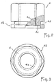
- the base 4 b of the nut has a counterbore 4 c and a groove 4 d , the characteristics of which will not be described again since they correspond respectively to those of the counterbore 1 c and of the groove 1 d described with reference to FIG. 1 .
- the tapping of the nut extends up to the countersinking 4 c of the base 4 b , which can be constituted by a circular collar, as seen in the figures, or on the contrary, have a corresponding hexagonal shape. to that of the nut body 4.
Claims (5)
Priority Applications (1)
| Application Number | Priority Date | Filing Date | Title |
|---|---|---|---|
| AT88402575T ATE62978T1 (de) | 1987-11-03 | 1988-10-12 | Deformierbare unterlegscheibe, insbesondere geeignet zum vorherbestimmen der mindestklemmkraft einer mutter oder eines bolzens. |
Applications Claiming Priority (2)
| Application Number | Priority Date | Filing Date | Title |
|---|---|---|---|
| FR8715235 | 1987-11-03 | ||
| FR8715235A FR2622648B1 (fr) | 1987-11-03 | 1987-11-03 | Rondelle deformable, permettant notamment de predeterminer la force minimale de serrage d'un ecrou ou d'une vis |
Publications (2)
| Publication Number | Publication Date |
|---|---|
| EP0315501A1 EP0315501A1 (de) | 1989-05-10 |
| EP0315501B1 true EP0315501B1 (de) | 1991-04-24 |
Family
ID=9356442
Family Applications (1)
| Application Number | Title | Priority Date | Filing Date |
|---|---|---|---|
| EP88402575A Expired - Lifetime EP0315501B1 (de) | 1987-11-03 | 1988-10-12 | Deformierbare Unterlegscheibe, insbesondere geeignet zum Vorherbestimmen der Mindestklemmkraft einer Mutter oder eines Bolzens |
Country Status (18)
| Country | Link |
|---|---|
| US (1) | US4887948A (de) |
| EP (1) | EP0315501B1 (de) |
| JP (1) | JPH01150010A (de) |
| KR (1) | KR890008468A (de) |
| AT (1) | ATE62978T1 (de) |
| BG (1) | BG49166A3 (de) |
| BR (1) | BR8805710A (de) |
| CA (1) | CA1302752C (de) |
| CZ (1) | CZ278951B6 (de) |
| DD (1) | DD283449A5 (de) |
| DE (1) | DE3862567D1 (de) |
| ES (1) | ES2022673B3 (de) |
| FR (1) | FR2622648B1 (de) |
| GR (1) | GR3002211T3 (de) |
| HU (1) | HU207379B (de) |
| PT (1) | PT88839B (de) |
| RO (1) | RO103816B1 (de) |
| YU (1) | YU204188A (de) |
Cited By (1)
| Publication number | Priority date | Publication date | Assignee | Title |
|---|---|---|---|---|
| DE4421959A1 (de) * | 1994-06-23 | 1996-01-04 | Fischer Artur Werke Gmbh | Vorspannkontrollelement für Schraubanker |
Families Citing this family (33)
| Publication number | Priority date | Publication date | Assignee | Title |
|---|---|---|---|---|
| US4979857A (en) * | 1989-02-22 | 1990-12-25 | Wing George S | Extended counterbore nut |
| US5370483A (en) * | 1993-06-24 | 1994-12-06 | J & M Turner, Inc. | Direct tension indicator washer |
| US5704572A (en) * | 1995-10-06 | 1998-01-06 | Illinois Tool Works Inc. | Method and apparatus for fastening |
| US5667346A (en) * | 1996-02-06 | 1997-09-16 | F. Jonathan M. Turner | Direct tension indicator washer |
| US7111767B2 (en) | 1997-04-24 | 2006-09-26 | Simpson Strong-Tie Company, Inc. | Power actuated fastener system |
| US6095733A (en) * | 1998-06-29 | 2000-08-01 | Huck International, Inc. | Threaded fastener with determinable clamp load |
| US6030305A (en) * | 1998-09-28 | 2000-02-29 | Ingersoll-Rand Company | Semi-automatic tensioner for a belt drive system |
| US6109848A (en) * | 1999-06-09 | 2000-08-29 | Emhart Inc. | Plastic nut with molded washer |
| US6135687A (en) * | 1999-07-02 | 2000-10-24 | Simpson Strong-Tie Co., Inc. | Direct tension indicator for embedded anchor members |
| US7509778B2 (en) | 2000-12-03 | 2009-03-31 | Simpson Strong-Tie Company, Inc. | Automatic take-up device with internal spring |
| US6609868B2 (en) * | 2001-12-06 | 2003-08-26 | John K. Junkers | Washer, fastener provided with a washer, and method of fastening with the use of the washer |
| US7125213B2 (en) * | 2001-12-06 | 2006-10-24 | Junkers John K | Washer, fastener provided with a washer, method of and power tool for fastening objects |
| US7207760B2 (en) * | 2001-12-06 | 2007-04-24 | Junkers John K | Washer and fastener provided with a washer |
| US7066053B2 (en) * | 2002-03-29 | 2006-06-27 | Junkers John K | Washer, fastener provided with a washer |
| US7249701B2 (en) | 2002-11-05 | 2007-07-31 | Simpson Strong-Tie Co., Inc. | Power actuated gun with fastener feeding track and automatic firing |
| US20050158145A1 (en) * | 2004-01-16 | 2005-07-21 | Junkers John K. | Washer, fastener provided with a washer, method of and power tool for fastening objects |
| US20050155461A1 (en) * | 2004-01-15 | 2005-07-21 | Junkers John K. | Washer, fastener provided with a washer, method of and power tool for fastening objects |
| US7168343B2 (en) | 2005-03-09 | 2007-01-30 | Simpson Strong-Tie Company, Inc. | Limited access building connection |
| US7905066B2 (en) | 2007-04-06 | 2011-03-15 | Simpson Strong-Tie Co., Inc. | Automatic take-up device and in-line coupler |
| US8978232B2 (en) * | 2009-03-23 | 2015-03-17 | John K. Junkers | Method for tightening and loosening threaded connectors |
| FR2957990B1 (fr) * | 2010-03-24 | 2012-04-13 | Sainte Lizaigne Sa | Rondelle de controle de serrage, ensemble de serrage et collier de prise en charge sur conduite |
| DE102011007940B4 (de) * | 2011-01-03 | 2019-02-21 | Wolfgang B. Thörner | Polklemme |
| US8881478B2 (en) | 2012-06-22 | 2014-11-11 | Simpson Strong-Tie Company, Inc. | Ratcheting take-up device |
| US8974164B2 (en) | 2012-06-26 | 2015-03-10 | Newfrey Llc | Plastic high heat fastener |
| US9394706B2 (en) | 2013-10-08 | 2016-07-19 | Simpson Strong-Tie Company, Inc. | Concrete anchor |
| US9163655B2 (en) | 2014-01-14 | 2015-10-20 | Kaoru Taneichi | Thrust nut |
| US9863457B2 (en) * | 2015-11-11 | 2018-01-09 | Turnasure Llc | Direct tension indicating washer with offset protuberances and indentations |
| US10738817B2 (en) | 2017-04-11 | 2020-08-11 | Turnasure Llc | Self-indicating direct tension indicator |
| US10465739B2 (en) * | 2017-06-30 | 2019-11-05 | Bae Systems Information And Electronic Systems Integration Inc. | Apparatus for securing an image sensor within a night vision device |
| FR3092882B1 (fr) * | 2019-02-19 | 2022-10-14 | Lionel Utille | Dispositif de visualisation de perte de tension dans un assemblage |
| CA3089416A1 (en) * | 2019-08-07 | 2021-02-07 | Markus J. Hess | Compression contact to monitor fastener elongation and grip force |
| CN112377510B (zh) * | 2020-09-27 | 2022-08-05 | 沪东中华造船(集团)有限公司 | 一种管路法兰螺纹紧固力矩指示方法 |
| US20230082125A1 (en) * | 2021-09-13 | 2023-03-16 | Airbus Operations Sas | Scored spacer element serving to obtain a spacer washer positioned between parts of an assembly, and method for assembling at least two parts using at least one such scored spacer element |
Family Cites Families (8)
| Publication number | Priority date | Publication date | Assignee | Title |
|---|---|---|---|---|
| FR1040829A (fr) * | 1950-09-11 | 1953-10-19 | Manuf D Engins De Prec Pour Pe | Perfectionnements aux écrous, ou autres pièces taraudées, en vue de les rendre pratiquement indesserrables |
| US3306154A (en) * | 1965-10-23 | 1967-02-28 | Mcculloch Corp | Compressive load limit indicators |
| US3602976A (en) * | 1969-09-15 | 1971-09-07 | Mac Lean Fogg Lock Nut Co | Method for controlling clamping load of a threaded fastener |
| US3728933A (en) * | 1971-03-11 | 1973-04-24 | Mac Lean Fogg Lock Nut Co | Means and method for controlling tension in a threaded member |
| JPS5018852A (de) * | 1973-06-19 | 1975-02-27 | ||
| US3948141A (en) * | 1974-08-20 | 1976-04-06 | Katsumi Shinjo | Load indicating washer |
| SU634023A1 (ru) * | 1977-02-03 | 1978-11-25 | Pospeev Vladimir Ya | Самоконтр ща с гайка |
| GB2107018A (en) * | 1981-09-29 | 1983-04-20 | Glynwed Limited | Bolt tension indicator |
-
1987
- 1987-11-03 FR FR8715235A patent/FR2622648B1/fr not_active Expired - Lifetime
-
1988
- 1988-10-12 EP EP88402575A patent/EP0315501B1/de not_active Expired - Lifetime
- 1988-10-12 DE DE8888402575T patent/DE3862567D1/de not_active Expired - Fee Related
- 1988-10-12 AT AT88402575T patent/ATE62978T1/de not_active IP Right Cessation
- 1988-10-12 ES ES88402575T patent/ES2022673B3/es not_active Expired - Lifetime
- 1988-10-17 US US07/258,657 patent/US4887948A/en not_active Expired - Fee Related
- 1988-10-20 KR KR1019880013682A patent/KR890008468A/ko not_active Application Discontinuation
- 1988-10-20 HU HU885420A patent/HU207379B/hu not_active IP Right Cessation
- 1988-10-21 CA CA000580890A patent/CA1302752C/en not_active Expired - Fee Related
- 1988-10-24 PT PT88839A patent/PT88839B/pt not_active IP Right Cessation
- 1988-10-26 BR BR888805710A patent/BR8805710A/pt unknown
- 1988-10-27 JP JP63271909A patent/JPH01150010A/ja active Pending
- 1988-11-01 CZ CS887184A patent/CZ278951B6/cs unknown
- 1988-11-01 BG BG85892A patent/BG49166A3/xx unknown
- 1988-11-01 DD DD88321317A patent/DD283449A5/de not_active IP Right Cessation
- 1988-11-02 RO RO135721A patent/RO103816B1/ro unknown
- 1988-11-03 YU YU02041/88A patent/YU204188A/xx unknown
-
1991
- 1991-06-27 GR GR91400890T patent/GR3002211T3/el unknown
Cited By (1)
| Publication number | Priority date | Publication date | Assignee | Title |
|---|---|---|---|---|
| DE4421959A1 (de) * | 1994-06-23 | 1996-01-04 | Fischer Artur Werke Gmbh | Vorspannkontrollelement für Schraubanker |
Also Published As
| Publication number | Publication date |
|---|---|
| HU207379B (en) | 1993-03-29 |
| GR3002211T3 (en) | 1992-12-30 |
| CZ718488A3 (en) | 1994-05-18 |
| BG49166A3 (en) | 1991-08-15 |
| YU204188A (en) | 1990-12-31 |
| CZ278951B6 (en) | 1994-10-19 |
| KR890008468A (ko) | 1989-07-10 |
| PT88839B (pt) | 1993-12-31 |
| FR2622648A1 (fr) | 1989-05-05 |
| DE3862567D1 (de) | 1991-05-29 |
| ES2022673B3 (es) | 1991-12-01 |
| RO103816B1 (en) | 1993-12-03 |
| PT88839A (pt) | 1989-09-14 |
| DD283449A5 (de) | 1990-10-10 |
| ATE62978T1 (de) | 1991-05-15 |
| BR8805710A (pt) | 1989-07-18 |
| FR2622648B1 (fr) | 1990-03-09 |
| CA1302752C (en) | 1992-06-09 |
| EP0315501A1 (de) | 1989-05-10 |
| US4887948A (en) | 1989-12-19 |
| JPH01150010A (ja) | 1989-06-13 |
| HUT49676A (en) | 1989-10-30 |
Similar Documents
| Publication | Publication Date | Title |
|---|---|---|
| EP0315501B1 (de) | Deformierbare Unterlegscheibe, insbesondere geeignet zum Vorherbestimmen der Mindestklemmkraft einer Mutter oder eines Bolzens | |
| EP0389308B1 (de) | Befestigungsmittel und Verfahren zur Ausführung besagter Mittel | |
| US3473202A (en) | Prestressed shaft engaging unit | |
| FR2501093A1 (fr) | Outil d'alesage ou de percage utilisable comme barre d'alesage ou comme tige porte-foret | |
| FR2809144A1 (fr) | Ensemble a organe de fixation de roue, et organe de fixation | |
| EP1162376A1 (de) | Befestigungsvorrichtung mit einer Vertiefung am Ende ihres Gewindestabes | |
| FR2638796A1 (fr) | Dispositif d'assemblage a ecrou-barillet flottant | |
| EP0402198B1 (de) | Verriegelungsmutter | |
| EP0551047B1 (de) | Haltevorrichtung mit entfernbarer Zentrierbüchse | |
| WO2003022603A1 (fr) | Dispositif de montage d'un capteur sur une jante de roue de vehicule automobile et procede de montage associe | |
| EP1588897B1 (de) | Haltemittel und zugehöriges Fahrzeug | |
| EP0373049B1 (de) | Vorrichtung zum Befestigen eines Ausrüstungsstückes auf einem Teil des Innenaufbaus eines Fahrzeuges in einer relativen Stellung zum Aussenaufbau | |
| EP0112766A1 (de) | Scheibenbremssattel mit entblockbarer Verstärkung | |
| WO1998026325A1 (fr) | Dispositif a charniere | |
| FR2720845A1 (fr) | Vis de réglage. | |
| FR2672548A1 (fr) | Dispositif de fixation d'une extremite d'amortisseur telescopique sur la caisse d'un vehicule automobile. | |
| CH695389A5 (fr) | Dispositif d'assemblage à vis d'au moins deux pièces, notamment de maillons de bracelet. | |
| EP3859170B1 (de) | Bolzen, der eine mutter und mindestens eine unterlegscheibe umfasst, die durch härtung eines pastösen materials erhalten wurde, verfahren zur montage dieses bolzens und baugruppe mit mindestens einem solchen bolzen | |
| EP0507712A1 (de) | Verbindungsvorrichtung für zwei schwenkende Schenkel eines Werkzeugs | |
| EP2841774B1 (de) | Element zur befestigung eines zubehörteils an einer halterung und der halterung an einer struktur | |
| FR2826698A1 (fr) | Ensemble de fixation, module et fourreau de protection correspondants | |
| FR2491804A1 (fr) | Mandrin de serrage pour queue d'outil cylindrique | |
| EP0974423B1 (de) | Koppelungsmechanismus zwischen einer Werkzeug-Antriebsvorrichtung und einem Werkzeug, insbesondere für ophtalmische Linse Endbearbeitungswerkzeug, und Verfahren zur Anwendung desselben | |
| FR2620365A1 (fr) | Dispositif de serrage d'outils en forme de disques sur la broche de travail d'une machine-outil portative, en particulier d'une meuleuse | |
| EP0524105B1 (de) | Nichtabmontierbares Zwischenstück, insbesondere zum Einstellen der Orientierung von Fahrzeugscheinwerfern |
Legal Events
| Date | Code | Title | Description |
|---|---|---|---|
| PUAI | Public reference made under article 153(3) epc to a published international application that has entered the european phase |
Free format text: ORIGINAL CODE: 0009012 |
|
| AK | Designated contracting states |
Kind code of ref document: A1 Designated state(s): AT BE CH DE ES GB GR IT LI LU NL SE |
|
| 17P | Request for examination filed |
Effective date: 19890313 |
|
| 17Q | First examination report despatched |
Effective date: 19900709 |
|
| GRAA | (expected) grant |
Free format text: ORIGINAL CODE: 0009210 |
|
| AK | Designated contracting states |
Kind code of ref document: B1 Designated state(s): AT BE CH DE ES GB GR IT LI LU NL SE |
|
| REF | Corresponds to: |
Ref document number: 62978 Country of ref document: AT Date of ref document: 19910515 Kind code of ref document: T |
|
| REF | Corresponds to: |
Ref document number: 3862567 Country of ref document: DE Date of ref document: 19910529 |
|
| GBT | Gb: translation of ep patent filed (gb section 77(6)(a)/1977) | ||
| ITF | It: translation for a ep patent filed |
Owner name: JACOBACCI & PERANI S.P.A. |
|
| PLBE | No opposition filed within time limit |
Free format text: ORIGINAL CODE: 0009261 |
|
| STAA | Information on the status of an ep patent application or granted ep patent |
Free format text: STATUS: NO OPPOSITION FILED WITHIN TIME LIMIT |
|
| 26N | No opposition filed | ||
| REG | Reference to a national code |
Ref country code: GR Ref legal event code: FG4A Free format text: 3002211 |
|
| NLR1 | Nl: opposition has been filed with the epo |
Opponent name: ROCKWOOL/GRODAN B.V. |
|
| PGFP | Annual fee paid to national office [announced via postgrant information from national office to epo] |
Ref country code: AT Payment date: 19930923 Year of fee payment: 6 |
|
| PGFP | Annual fee paid to national office [announced via postgrant information from national office to epo] |
Ref country code: GR Payment date: 19930929 Year of fee payment: 6 |
|
| PGFP | Annual fee paid to national office [announced via postgrant information from national office to epo] |
Ref country code: GB Payment date: 19931005 Year of fee payment: 6 |
|
| PGFP | Annual fee paid to national office [announced via postgrant information from national office to epo] |
Ref country code: ES Payment date: 19931014 Year of fee payment: 6 |
|
| PGFP | Annual fee paid to national office [announced via postgrant information from national office to epo] |
Ref country code: LU Payment date: 19931015 Year of fee payment: 6 Ref country code: CH Payment date: 19931015 Year of fee payment: 6 |
|
| PGFP | Annual fee paid to national office [announced via postgrant information from national office to epo] |
Ref country code: DE Payment date: 19931025 Year of fee payment: 6 |
|
| PGFP | Annual fee paid to national office [announced via postgrant information from national office to epo] |
Ref country code: SE Payment date: 19931026 Year of fee payment: 6 |
|
| PGFP | Annual fee paid to national office [announced via postgrant information from national office to epo] |
Ref country code: NL Payment date: 19931031 Year of fee payment: 6 |
|
| PGFP | Annual fee paid to national office [announced via postgrant information from national office to epo] |
Ref country code: BE Payment date: 19931115 Year of fee payment: 6 |
|
| EPTA | Lu: last paid annual fee | ||
| PG25 | Lapsed in a contracting state [announced via postgrant information from national office to epo] |
Ref country code: LU Free format text: LAPSE BECAUSE OF NON-PAYMENT OF DUE FEES Effective date: 19941012 Ref country code: GB Effective date: 19941012 Ref country code: AT Effective date: 19941012 |
|
| PG25 | Lapsed in a contracting state [announced via postgrant information from national office to epo] |
Ref country code: SE Effective date: 19941013 Ref country code: ES Free format text: LAPSE BECAUSE OF EXPIRATION OF PROTECTION Effective date: 19941013 |
|
| PG25 | Lapsed in a contracting state [announced via postgrant information from national office to epo] |
Ref country code: LI Effective date: 19941031 Ref country code: CH Effective date: 19941031 Ref country code: BE Effective date: 19941031 |
|
| EAL | Se: european patent in force in sweden |
Ref document number: 88402575.0 |
|
| BERE | Be: lapsed |
Owner name: ETS CAILLAU Effective date: 19941031 |
|
| PG25 | Lapsed in a contracting state [announced via postgrant information from national office to epo] |
Ref country code: GR Free format text: THE PATENT HAS BEEN ANNULLED BY A DECISION OF A NATIONAL AUTHORITY Effective date: 19950430 |
|
| PG25 | Lapsed in a contracting state [announced via postgrant information from national office to epo] |
Ref country code: NL Effective date: 19950501 |
|
| GBPC | Gb: european patent ceased through non-payment of renewal fee |
Effective date: 19941012 |
|
| NLV4 | Nl: lapsed or anulled due to non-payment of the annual fee | ||
| REG | Reference to a national code |
Ref country code: CH Ref legal event code: PL Ref country code: GR Ref legal event code: MM2A Free format text: 3002211 |
|
| PG25 | Lapsed in a contracting state [announced via postgrant information from national office to epo] |
Ref country code: DE Effective date: 19950701 |
|
| EUG | Se: european patent has lapsed |
Ref document number: 88402575.0 |
|
| REG | Reference to a national code |
Ref country code: ES Ref legal event code: FD2A Effective date: 20010201 |
|
| PG25 | Lapsed in a contracting state [announced via postgrant information from national office to epo] |
Ref country code: IT Free format text: LAPSE BECAUSE OF NON-PAYMENT OF DUE FEES;WARNING: LAPSES OF ITALIAN PATENTS WITH EFFECTIVE DATE BEFORE 2007 MAY HAVE OCCURRED AT ANY TIME BEFORE 2007. THE CORRECT EFFECTIVE DATE MAY BE DIFFERENT FROM THE ONE RECORDED. Effective date: 20051012 |