EP0314476A2 - Compensation de seuil par rétroaction - Google Patents
Compensation de seuil par rétroaction Download PDFInfo
- Publication number
- EP0314476A2 EP0314476A2 EP88310114A EP88310114A EP0314476A2 EP 0314476 A2 EP0314476 A2 EP 0314476A2 EP 88310114 A EP88310114 A EP 88310114A EP 88310114 A EP88310114 A EP 88310114A EP 0314476 A2 EP0314476 A2 EP 0314476A2
- Authority
- EP
- European Patent Office
- Prior art keywords
- shifter
- voltage
- bias
- input
- sinking
- Prior art date
- Legal status (The legal status is an assumption and is not a legal conclusion. Google has not performed a legal analysis and makes no representation as to the accuracy of the status listed.)
- Ceased
Links
Images


Classifications
-
- H—ELECTRICITY
- H03—ELECTRONIC CIRCUITRY
- H03K—PULSE TECHNIQUE
- H03K19/00—Logic circuits, i.e. having at least two inputs acting on one output; Inverting circuits
- H03K19/003—Modifications for increasing the reliability for protection
- H03K19/00369—Modifications for compensating variations of temperature, supply voltage or other physical parameters
- H03K19/00384—Modifications for compensating variations of temperature, supply voltage or other physical parameters in field effect transistor circuits
-
- G—PHYSICS
- G05—CONTROLLING; REGULATING
- G05F—SYSTEMS FOR REGULATING ELECTRIC OR MAGNETIC VARIABLES
- G05F3/00—Non-retroactive systems for regulating electric variables by using an uncontrolled element, or an uncontrolled combination of elements, such element or such combination having self-regulating properties
- G05F3/02—Regulating voltage or current
- G05F3/08—Regulating voltage or current wherein the variable is dc
- G05F3/10—Regulating voltage or current wherein the variable is dc using uncontrolled devices with non-linear characteristics
- G05F3/16—Regulating voltage or current wherein the variable is dc using uncontrolled devices with non-linear characteristics being semiconductor devices
- G05F3/20—Regulating voltage or current wherein the variable is dc using uncontrolled devices with non-linear characteristics being semiconductor devices using diode- transistor combinations
- G05F3/24—Regulating voltage or current wherein the variable is dc using uncontrolled devices with non-linear characteristics being semiconductor devices using diode- transistor combinations wherein the transistors are of the field-effect type only
- G05F3/242—Regulating voltage or current wherein the variable is dc using uncontrolled devices with non-linear characteristics being semiconductor devices using diode- transistor combinations wherein the transistors are of the field-effect type only with compensation for device parameters, e.g. channel width modulation, threshold voltage, processing, or external variations, e.g. temperature, loading, supply voltage
- G05F3/245—Regulating voltage or current wherein the variable is dc using uncontrolled devices with non-linear characteristics being semiconductor devices using diode- transistor combinations wherein the transistors are of the field-effect type only with compensation for device parameters, e.g. channel width modulation, threshold voltage, processing, or external variations, e.g. temperature, loading, supply voltage producing a voltage or current as a predetermined function of the temperature
-
- G—PHYSICS
- G05—CONTROLLING; REGULATING
- G05F—SYSTEMS FOR REGULATING ELECTRIC OR MAGNETIC VARIABLES
- G05F3/00—Non-retroactive systems for regulating electric variables by using an uncontrolled element, or an uncontrolled combination of elements, such element or such combination having self-regulating properties
- G05F3/02—Regulating voltage or current
- G05F3/08—Regulating voltage or current wherein the variable is dc
- G05F3/10—Regulating voltage or current wherein the variable is dc using uncontrolled devices with non-linear characteristics
- G05F3/16—Regulating voltage or current wherein the variable is dc using uncontrolled devices with non-linear characteristics being semiconductor devices
- G05F3/20—Regulating voltage or current wherein the variable is dc using uncontrolled devices with non-linear characteristics being semiconductor devices using diode- transistor combinations
- G05F3/24—Regulating voltage or current wherein the variable is dc using uncontrolled devices with non-linear characteristics being semiconductor devices using diode- transistor combinations wherein the transistors are of the field-effect type only
- G05F3/242—Regulating voltage or current wherein the variable is dc using uncontrolled devices with non-linear characteristics being semiconductor devices using diode- transistor combinations wherein the transistors are of the field-effect type only with compensation for device parameters, e.g. channel width modulation, threshold voltage, processing, or external variations, e.g. temperature, loading, supply voltage
- G05F3/247—Regulating voltage or current wherein the variable is dc using uncontrolled devices with non-linear characteristics being semiconductor devices using diode- transistor combinations wherein the transistors are of the field-effect type only with compensation for device parameters, e.g. channel width modulation, threshold voltage, processing, or external variations, e.g. temperature, loading, supply voltage producing a voltage or current as a predetermined function of the supply voltage
-
- H—ELECTRICITY
- H03—ELECTRONIC CIRCUITRY
- H03K—PULSE TECHNIQUE
- H03K19/00—Logic circuits, i.e. having at least two inputs acting on one output; Inverting circuits
- H03K19/0175—Coupling arrangements; Interface arrangements
- H03K19/0185—Coupling arrangements; Interface arrangements using field effect transistors only
- H03K19/018507—Interface arrangements
- H03K19/018535—Interface arrangements of Schottky barrier type [MESFET]
Definitions
- Emitter Coupled Logic typically F 100K or 10KH series made by Fairchild and Motorola, respectively
- ⁇ V L logic swings
- V th for GaAs MESFET logic circuits are not a good match for ECL thresholds. Even F 100K and 10KH versions of ECL do not match each other in this regard, let alone normal (uncompensated) GaAs circuuits.
- CDFL Capacitor Diode FET Logic
- V SS intermediate V SS potential
- V DD -V SS logic threshold voltage
- the present invention uses a variation of CDFL combined with feedback to achieve V BB to V th compatability.
- One of the substantial advantages of the CDFL approach is that it can accomplish ECL input level transition without significant propagation delay.
- the undelayed ECL input may be used directly in logic functions for a substantial savings in delay time.
- differential input translators costs at least one stage of propagation delay, which is wasted unless the internal chip logic requires both the true and complement forms of the input, such as in address drivers in a Random Access Memory or in Multiplexers. For this reason, differential inputs are used only when both polarities of the input signal are required.
- the present invention extends the CDFL circuit approach to one in which the shift voltages across the input level shift circuits on all inputs are adjusted in such a way as to maintain a threshold voltage equal to the dc potential on an "extra" V BB input, in spite of variations of temperature, power supply voltages or processing parametes such as MESFET pinchoff voltage, V p .
- ECL compatability is accomplished by combining a reasonably compliant, but uniform, CDFL voltage shifter with feedback circuitry to maintain the shift voltages at proper levels thereby achieving the desired input logic threshold. This technique has proven quite effective.
- a further object of the present invention is to provide stable interface circuitry between ECL and GaAs semiconductors without adding significant propagation delay.
- FIGS 1A, 1B and 1C show three versions of the voltage shifter circuit required for CDFL logic circuits.
- the ac or transient logic signal currents are passed through a capacitor of some type, shown as a large-area reverse-biased Schottky diode capacitor 20 or "DCAP", which is maintained in reverse-bias by a small, approximately 10 ⁇ A to 250 ⁇ A typically, trickle current, I BIAS .
- I BIAS is provided by some type of controllable current-sinking device connected to, or near the most negative supply, or V EE , which is usually -5.2V.
- V EE which is usually -5.2V.
- the capacitance of the DCAP 20 must be many times the load capacitance to avoid ac signal voltage loss.
- V SHIFT V th + V gsB (voltage gate to source in Balance)
- the single-bias circuit of Figure 1C shows a series/shunt resistor modification of the circuit of Figure 1A which has enough compliance to give adequate V SHIFT range.
- Diode 26 is modified with enough series resistance, resistor 30, to allow, at high I BIAS , its voltage drop to be increased well beyond the normal forward drop, or V F (which is approximately 0.75V at room temperature).
- V F which is approximately 0.75V at room temperature.
- a shunt resistor 32 will reduce the drop far below V F .
- a side advantage of the implanted N+ resistors 30 and 32, is that their positive temperature coefficient helps cancel some of the negative temperature coefficient of V F , even without intervention of the V BB feedback control of I BIAS .
- V BB -Feedback approach using the very uniform controlled-dc compliance shifter of Figure 1C is illustrated in the block diagram of the Figure 2.
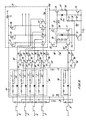
- a transistor-level implementation of the present invention is shown in Figure 3.
- the key concepts in the approach are that all of the logic inputs on the GaAs IC, plus the "extra" V BB input, have identical shifters 34 ( Figures 1C and 2) biased from identical pulldown FETs 36 to V EE which are all controlled from the same gate potential, V FBT (feedback trim voltage) on line 38 so that they all generate identical (controllable) shifter bias currents I BIAS .
- V BB -Feedback input gate 40 the input threshold voltage of all input gates is at the V BB potential. This means that if a dc input level of V BB is applied to an input gate, its output goes to a dc level equal to the threshold voltage of any gate inputs connected to that output. This is shown by the feedback path of Figure 2 which includes V BB -Feedback input gate 40, typical internal input gate 42, loop filter elements 51 and 53 and buffer 46.
- V BB feedback input gate 40 (comprising switching FET 49, active load 48 and normal CDFL interstage level shifter 50 shown in Figure 3) is connected to the input of a "typical" internal input gate 42 (comprising switching FET 71 and active load 72 shown in Figure 3) having a FET to pullup width ratio the same as generally used in internal gates on the chip.
- a "typical" internal input gate 42 (comprising switching FET 71 and active load 72 shown in Figure 3) having a FET to pullup width ratio the same as generally used in internal gates on the chip.
- This source-follower buffer 46 shown as FET 73 with pulldown FET 74 in Figure 3, also contains voltage-shifting elements, corresponding to battery 48 in Figure 2, diodes 75, 76, 77 and 78, with resistor 79 biasing the diodes 77 and 78, required to obtain V FBT voltages near V EE , since the sources of the pulldown bias FETs 36 are near V EE .
- V EE is the most negative supply potential on the GaAs IC (-5.2V).
- the source of the FETS 36 are held at a small bias potential, typically 0.4V above V EE , by a small resistor/diode circuit, shown as a battery 54 in Figure 3, so that the I BIAS range can be adequately controlled.
- This V EE + 0.4 volt potential has been generated, for example, by connecting the cathode of a forward-based diode to V EE , and which is biased with an FET whose gate and source are connected to the diode anode, and whose drain is connected to V SS .
- V BB -Feedback input threshold stabilization concept was carried out on a redesign of an original PicoLogic 10G000 quad NOR gate manufactured by Gigabit Logic.
- the major issues in the testing of the V BB feedback circuits included verifying close tracking of logic thresholds, V th , to the V BB potential over the requisite V BB range of the ECL being used, maintenance of a constant V th as the V SS supply potential is varied and demonstration of the stability of the V BB feedback loop. In the experimental chips, no instabilities or oscillations in the feedback loop were observed, indicating adequate phase margins in the loop response were achieved.
- Figure 4 is a graph of the measured V th versus the V BB input reference level supplied to a GaAs IC, where V th is defined as the value of the logic input voltage which gives a logic output level of -1.30V.
- V DD 0
- V SS - 3.40V
- V EE -5.2V
- the slope of the V th versus V BB curve is slightly greater than unity, 1.06, but the match between V th and V BB is excellent; few tens of millivolts over more than a volt of V BB range.
- the measured variation of V th with V SS is illustrated in Figure 5.
- V BB potential should be obtained from the ECL part.
- Some ECL parts provide V BB threshold voltage dc outputs.
- the level may be generated by the dc feedback of an ECL inverter's output connected back to its input.
- ECL ICs to GaAs outputs, which typically provide output swings of at least -0.8V to -1.8V, or commonly -0.6 to -2.0V, such precise threshold control is not required.
- V BBS a fixed V BB supply potential
- V th threshold voltage Another issue is the variation in the V th threshold voltage obtained between various inputs on the same chip.
- CDFL gates with precision diode shifters give very tight distributions (standard deviation for V th is approximately 33mV) for the inputs on a given chip.
- V BB -Feedback threshold control With the greater compliance shifter of Figure 1C, needed for V BB -Feedback threshold control, the statistical variation of V th is degraded somewhat due to the small variations in I BIAS caused by statistical variaions among the small pulldown FETs. For example, within one chip using V BB -Feedback, a standard deviation of V th of 43mV was obtained with a 100mV worst-case departure of V th from V BB over 12 inputs.
- V BB feedback circuitry for achieving ECL input compatibility does not degrade the dynamic circuit performance of the GaAs IC's with their 100 to 150 ps output rise/fall times.
- V BB -Feedback An improvement in the V BB -Feedback Circuit Approach is called “Push-Pull" V BB -Feedback.
- V SC ⁇ 0.4V a fixed potential 54
- This 0.4V sets the lower limit to the I BIAS value. Unfortunately, it not only limits the V SHIFT range, but it also limits the lower extent of the V g -V EE range, so its value may not be arbitrarily increased. For instance, without V SC , V g -V SS could go 0.4V lower while maintaining the V ds of the bias FET 36 in the proper saturated-drain range. Also, the 0.4V bias generator 54 takes power, typically 2mA from V SS to V EE in the usual FET-resistor-diode implementation described previously.
- V BB -Feedback In general, it is good practice when using V BB -Feedback, for uniformity of V th to run a separate V EE line for the input shifter pulldowns 36, as variations in V EE due to IR drops along the V EE line would lead to variations of I BIAS for the shifter, and hence variations of V th .
- this extra line 58 (V SFB ) is run specifically for the sources of the input shifter pulldowns 36.
- V SFB line 58 Figure 7 or Figure 9 which is a transistor level implementation of the circuit shown in Figure 7
- V FBT V EE
- V SFB V EE
- V SFB V EE
- I BIAS I BIAS can be increased far beyond I DSS , even with relatively modest values of V FBT -V EE ( ⁇ 0.4V better than with the previous approach).
- V SFB V SFB + V SHIFT
- Figure 9 represents one simple embodiment of the push-pull driver of Figure 7. Persons skilled in the art could design other circuits (such as differential amplifier circuits like that of Figure 10) which could perform this function.
- the circuit is identical to that of Figure 3 up through the creation of the V FBT gate feedback trim voltage on line 38.
- Elements 34 thru 79 of Figure 9 are connected the same as in Figure 3.
- an inverter/driver stage 90 including FET 80 and its source bias elements 85 and 86, its active load pullup 81 and shifter with diodes 82 and 83 biased by the resistor 84 to V EE .
- This inverter drives the V SFB feedback line driver comprising FETs 87 and 89 and diode 88.
- the drain of FET 87 may be connected to V SS rather than V DD as shown.
- This improved push-pull feedback configuration has been tested and found to give excellent performance over a wider temperature range and V SS variation than the single-ended circuit shown in Figure 3.
- a further improvement in the CDFL shifter approach which can be used with either the single-ended driver of Figure 3 or the push-pull drivers of Figures 9 or 10 are the Split-Pulldown shifters shown in Figures 8A and 8B.
- These CDFL voltage shifters limit the reduction of V shift which occurs in the shifter shown in Figure 1C when the logic signal input voltage at line 18 in Figures 8A or 8B or any of the logic inputs 12 to 15 shown in Figures 2 or 3 is taken so low that the V ds of the controlled pulldown current sink FET 36 goes below the saturated drain voltage, causing a reduction its drain current, I BIAS .
- the improvement is accomplished in the Split-Pulldown shifters by placing the compliant portion of the shifter, the series/parallel resistor-diode portion, resistors 30 and 32 and Diode 26, nearest the input, and running the majority of the bias current only through this portion of the shifter.
- This is advantageous, since the voltage at the intermediate bias node 106 ( Figure 8A) is ⁇ 0.75V higher than that at the shifter output, so that the V DS of the pulldown 136 never drops below drain saturation when the input on line 18 goes low.
- the voltage across the small pulldown, 96 in Figure 8A or 98 in Figure 8B can go below saturation, disturbing this trickle bias somewhat.
- this trickle bias through pulldowns 96 and 98 (typically 10uA to 50uA) is so small in comparison to the controlled bias through pulldown 136, Figures 8A and 8B, (typically 20uA to > 400uA) that the effect of the reduction in the trickle bias on line 108 on the overall shifter bias is greatly reduced (generally by a factor of 3 or more) over the simpler structure of Figure 1C.
- the trickle bias may be made either fixed, Figure 8A, at some sacrifice in I BIAS control range unless I trickle is made very small, or controlled as in Figure 8B which is more frequently used.
- Figure 10 shows a differential amplifier implementation of the push-pull feedback circuit of Figure 7. This implementation offers a generally wider performance range in bias voltage and temperature range as well as higher gain than the simpler circuit of Figure 9.
- Block 34 in Figure 10 corresponds to Block 34 in Figure 2 except that Block 34 of Figure 10 uses the split-pulldown arrangement of Figure 8B as opposed to the "single-bias" arrangement of Figure 1C.
- Block 34 in Figure 10 also eliminates the DCAP 20 which is optional on the V BB input of Figures 2, 3, 9 or 10.
- Block 40 in Figure 10 corresponds with Block 40 in Figure 2 and Block 11 in Figure 10 is the loop filter corresponding to the resistor 51/capacitor 53 loop filter of Figures 2 or 3.
- the remainder of the circuit of Figure 10 corresponds to the push-pull driver/inverter 55/90 of Figure 7.
Landscapes
- Engineering & Computer Science (AREA)
- Physics & Mathematics (AREA)
- Microelectronics & Electronic Packaging (AREA)
- Computer Hardware Design (AREA)
- Radar, Positioning & Navigation (AREA)
- General Physics & Mathematics (AREA)
- Electromagnetism (AREA)
- Automation & Control Theory (AREA)
- Nonlinear Science (AREA)
- Computing Systems (AREA)
- General Engineering & Computer Science (AREA)
- Mathematical Physics (AREA)
- Logic Circuits (AREA)
- Manipulation Of Pulses (AREA)
Applications Claiming Priority (2)
| Application Number | Priority Date | Filing Date | Title |
|---|---|---|---|
| US07/113,944 US4970413A (en) | 1987-10-28 | 1987-10-28 | VBB-feedback threshold compensation |
| US113944 | 1993-08-30 |
Publications (2)
| Publication Number | Publication Date |
|---|---|
| EP0314476A2 true EP0314476A2 (fr) | 1989-05-03 |
| EP0314476A3 EP0314476A3 (fr) | 1989-10-11 |
Family
ID=22352441
Family Applications (1)
| Application Number | Title | Priority Date | Filing Date |
|---|---|---|---|
| EP88310114A Ceased EP0314476A3 (fr) | 1987-10-28 | 1988-10-27 | Compensation de seuil par rétroaction |
Country Status (3)
| Country | Link |
|---|---|
| US (1) | US4970413A (fr) |
| EP (1) | EP0314476A3 (fr) |
| JP (1) | JPH021611A (fr) |
Cited By (2)
| Publication number | Priority date | Publication date | Assignee | Title |
|---|---|---|---|---|
| WO1994023353A1 (fr) * | 1993-04-05 | 1994-10-13 | National Semiconductor Corporation | Appareil et procede permettant d'ajuster la tension de seuil de transistors mos |
| WO2003012991A2 (fr) * | 2001-07-31 | 2003-02-13 | Telefonaktiebolaget L M Ericsson (Publ) | Dispositif de decalage de niveau avec gain |
Families Citing this family (5)
| Publication number | Priority date | Publication date | Assignee | Title |
|---|---|---|---|---|
| FR2653277A1 (fr) * | 1989-10-17 | 1991-04-19 | Thomson Composants Microondes | Circuit integre logique, a temps de basculement reglable. |
| JP3364154B2 (ja) * | 1998-05-22 | 2003-01-08 | 三菱電機株式会社 | 感熱式流量計 |
| US7667491B2 (en) * | 2006-02-24 | 2010-02-23 | Freescale Semiconductor, Inc. | Low voltage output buffer and method for buffering digital output data |
| US8154320B1 (en) * | 2009-03-24 | 2012-04-10 | Lockheed Martin Corporation | Voltage level shifter |
| US9787310B2 (en) | 2014-12-17 | 2017-10-10 | Silicon Laboratories Inc. | Level-shifter circuit for low-input voltages |
Citations (2)
| Publication number | Priority date | Publication date | Assignee | Title |
|---|---|---|---|---|
| EP0110701A2 (fr) * | 1982-11-27 | 1984-06-13 | Hitachi, Ltd. | Circuit tampon d'entrée |
| GB2166312A (en) * | 1984-10-22 | 1986-04-30 | Gigabit Logic Inc | Capacitor diode level shift circuit |
Family Cites Families (7)
| Publication number | Priority date | Publication date | Assignee | Title |
|---|---|---|---|---|
| US4423339A (en) * | 1981-02-23 | 1983-12-27 | Motorola, Inc. | Majority logic gate |
| JPS5819033A (ja) * | 1981-07-27 | 1983-02-03 | Nec Corp | 基本論理回路 |
| US4558235A (en) * | 1983-08-31 | 1985-12-10 | Texas Instruments Incorporated | MESFET logic gate having both DC and AC level shift coupling to the output |
| US4631426A (en) * | 1984-06-27 | 1986-12-23 | Honeywell Inc. | Digital circuit using MESFETS |
| US4651333A (en) * | 1984-10-29 | 1987-03-17 | Raytheon Company | Shift register memory cell having a transmission gate disposed between an inverter and a level shifter |
| US4663543A (en) * | 1985-09-19 | 1987-05-05 | Northern Telecom Limited | Voltage level shifting depletion mode FET logical circuit |
| US4661726A (en) * | 1985-10-31 | 1987-04-28 | Honeywell Inc. | Utilizing a depletion mode FET operating in the triode region and a depletion mode FET operating in the saturation region |
-
1987
- 1987-10-28 US US07/113,944 patent/US4970413A/en not_active Expired - Fee Related
-
1988
- 1988-10-27 JP JP63271908A patent/JPH021611A/ja active Pending
- 1988-10-27 EP EP88310114A patent/EP0314476A3/fr not_active Ceased
Patent Citations (2)
| Publication number | Priority date | Publication date | Assignee | Title |
|---|---|---|---|---|
| EP0110701A2 (fr) * | 1982-11-27 | 1984-06-13 | Hitachi, Ltd. | Circuit tampon d'entrée |
| GB2166312A (en) * | 1984-10-22 | 1986-04-30 | Gigabit Logic Inc | Capacitor diode level shift circuit |
Non-Patent Citations (2)
| Title |
|---|
| IEEE GaAs IC SYMPOSIUM TECHNICAL DIGEST, Boston, Massachusetts, 23rd-25th October 1984, pages 111-114, IEEE, New York, US; T. HAYASHI et al.: "ECL-compatible GaAs SRAM circuit technology for high performance computer application" * |
| IEEE GaAs IC SYMPOSIUM TECHNICAL DIGEST, Grenelefe, 28th-30th October 1986, pages 123-127, IEEE, New York, US; R.C. EDEN et al.: "VBB feedback approach for achieving ECL compatibility in GaAs ICs" * |
Cited By (4)
| Publication number | Priority date | Publication date | Assignee | Title |
|---|---|---|---|---|
| WO1994023353A1 (fr) * | 1993-04-05 | 1994-10-13 | National Semiconductor Corporation | Appareil et procede permettant d'ajuster la tension de seuil de transistors mos |
| WO2003012991A2 (fr) * | 2001-07-31 | 2003-02-13 | Telefonaktiebolaget L M Ericsson (Publ) | Dispositif de decalage de niveau avec gain |
| US6605974B2 (en) | 2001-07-31 | 2003-08-12 | Telefonaktiebolaget Lm Ericsson(Publ) | Level shifter with gain |
| WO2003012991A3 (fr) * | 2001-07-31 | 2003-11-06 | Ericsson Telefon Ab L M | Dispositif de decalage de niveau avec gain |
Also Published As
| Publication number | Publication date |
|---|---|
| US4970413A (en) | 1990-11-13 |
| EP0314476A3 (fr) | 1989-10-11 |
| JPH021611A (ja) | 1990-01-05 |
Similar Documents
| Publication | Publication Date | Title |
|---|---|---|
| US4912347A (en) | CMOS to ECL output buffer | |
| US5021691A (en) | Level conversion circuit having capability of supplying output signal with controlled logical level | |
| KR910006696B1 (ko) | 출력 인터페이스회로 | |
| US5903141A (en) | Current reference device in integrated circuit form | |
| US6111449A (en) | Clamping circuit for absorbing ringing of signal | |
| KR100248169B1 (ko) | 기판 바이어스전압 발생기용 조정회로 | |
| US4970413A (en) | VBB-feedback threshold compensation | |
| US5604457A (en) | Mixed mode output buffer circuit for CMOSIC | |
| US4845388A (en) | TTL-CMOS input buffer | |
| US5013941A (en) | TTL to ECL/CML translator circuit | |
| US5051626A (en) | Buffer circuit for logic level conversion | |
| EP0438706A2 (fr) | Circuit d'attaque CMOS à haute vitesse de commutation | |
| US5389842A (en) | Latch-up immune CMOS output driver | |
| US5107144A (en) | Integrated circuit having field effect transistors | |
| US5159208A (en) | Interface circuit provided between a compound semiconductor logic circuit and a bipolar transistor circuit | |
| US11671094B1 (en) | Driver circuit | |
| JPH077407A (ja) | 半導体集積回路装置 | |
| EP0354241A1 (fr) | Unite logique a transistors a effet de champ couples a une source de retro-action | |
| US6538487B2 (en) | Electrical circuit having inverters being serially connected together in a cascade | |
| GB2166312A (en) | Capacitor diode level shift circuit | |
| US5173622A (en) | Source coupled logic circuit with reduced power consumption | |
| KR100420689B1 (ko) | 버퍼회로 | |
| US5574391A (en) | ECL integrated circuit allowing fast operation | |
| US6051993A (en) | Level shift circuit compensating for circuit element characteristic variations | |
| US5631548A (en) | Power off-loading circuit and method for dissipating power |
Legal Events
| Date | Code | Title | Description |
|---|---|---|---|
| PUAI | Public reference made under article 153(3) epc to a published international application that has entered the european phase |
Free format text: ORIGINAL CODE: 0009012 |
|
| AK | Designated contracting states |
Kind code of ref document: A2 Designated state(s): AT BE CH DE ES FR GB GR IT LI LU NL SE |
|
| PUAL | Search report despatched |
Free format text: ORIGINAL CODE: 0009013 |
|
| AK | Designated contracting states |
Kind code of ref document: A3 Designated state(s): AT BE CH DE ES FR GB GR IT LI LU NL SE |
|
| 17P | Request for examination filed |
Effective date: 19891011 |
|
| 17Q | First examination report despatched |
Effective date: 19900625 |
|
| STAA | Information on the status of an ep patent application or granted ep patent |
Free format text: STATUS: THE APPLICATION HAS BEEN REFUSED |
|
| 18R | Application refused |
Effective date: 19920405 |