EP0314053B1 - Electroplating device for the thickening of a conductive line on a glass window - Google Patents
Electroplating device for the thickening of a conductive line on a glass window Download PDFInfo
- Publication number
- EP0314053B1 EP0314053B1 EP88117713A EP88117713A EP0314053B1 EP 0314053 B1 EP0314053 B1 EP 0314053B1 EP 88117713 A EP88117713 A EP 88117713A EP 88117713 A EP88117713 A EP 88117713A EP 0314053 B1 EP0314053 B1 EP 0314053B1
- Authority
- EP
- European Patent Office
- Prior art keywords
- electrolyte
- electroplating chamber
- electroplating
- removal
- anode
- Prior art date
- Legal status (The legal status is an assumption and is not a legal conclusion. Google has not performed a legal analysis and makes no representation as to the accuracy of the status listed.)
- Expired - Lifetime
Links
Images
Classifications
-
- H—ELECTRICITY
- H05—ELECTRIC TECHNIQUES NOT OTHERWISE PROVIDED FOR
- H05B—ELECTRIC HEATING; ELECTRIC LIGHT SOURCES NOT OTHERWISE PROVIDED FOR; CIRCUIT ARRANGEMENTS FOR ELECTRIC LIGHT SOURCES, IN GENERAL
- H05B3/00—Ohmic-resistance heating
- H05B3/84—Heating arrangements specially adapted for transparent or reflecting areas, e.g. for demisting or de-icing windows, mirrors or vehicle windshields
-
- C—CHEMISTRY; METALLURGY
- C25—ELECTROLYTIC OR ELECTROPHORETIC PROCESSES; APPARATUS THEREFOR
- C25D—PROCESSES FOR THE ELECTROLYTIC OR ELECTROPHORETIC PRODUCTION OF COATINGS; ELECTROFORMING; APPARATUS THEREFOR
- C25D17/00—Constructional parts, or assemblies thereof, of cells for electrolytic coating
- C25D17/004—Sealing devices
-
- C—CHEMISTRY; METALLURGY
- C25—ELECTROLYTIC OR ELECTROPHORETIC PROCESSES; APPARATUS THEREFOR
- C25D—PROCESSES FOR THE ELECTROLYTIC OR ELECTROPHORETIC PRODUCTION OF COATINGS; ELECTROFORMING; APPARATUS THEREFOR
- C25D17/00—Constructional parts, or assemblies thereof, of cells for electrolytic coating
- C25D17/02—Tanks; Installations therefor
-
- C—CHEMISTRY; METALLURGY
- C25—ELECTROLYTIC OR ELECTROPHORETIC PROCESSES; APPARATUS THEREFOR
- C25D—PROCESSES FOR THE ELECTROLYTIC OR ELECTROPHORETIC PRODUCTION OF COATINGS; ELECTROFORMING; APPARATUS THEREFOR
- C25D5/00—Electroplating characterised by the process; Pretreatment or after-treatment of workpieces
- C25D5/02—Electroplating of selected surface areas
-
- C—CHEMISTRY; METALLURGY
- C25—ELECTROLYTIC OR ELECTROPHORETIC PROCESSES; APPARATUS THEREFOR
- C25D—PROCESSES FOR THE ELECTROLYTIC OR ELECTROPHORETIC PRODUCTION OF COATINGS; ELECTROFORMING; APPARATUS THEREFOR
- C25D5/00—Electroplating characterised by the process; Pretreatment or after-treatment of workpieces
- C25D5/08—Electroplating with moving electrolyte e.g. jet electroplating
-
- H—ELECTRICITY
- H05—ELECTRIC TECHNIQUES NOT OTHERWISE PROVIDED FOR
- H05B—ELECTRIC HEATING; ELECTRIC LIGHT SOURCES NOT OTHERWISE PROVIDED FOR; CIRCUIT ARRANGEMENTS FOR ELECTRIC LIGHT SOURCES, IN GENERAL
- H05B2203/00—Aspects relating to Ohmic resistive heating covered by group H05B3/00
- H05B2203/016—Heaters using particular connecting means
-
- H—ELECTRICITY
- H05—ELECTRIC TECHNIQUES NOT OTHERWISE PROVIDED FOR
- H05K—PRINTED CIRCUITS; CASINGS OR CONSTRUCTIONAL DETAILS OF ELECTRIC APPARATUS; MANUFACTURE OF ASSEMBLAGES OF ELECTRICAL COMPONENTS
- H05K3/00—Apparatus or processes for manufacturing printed circuits
- H05K3/22—Secondary treatment of printed circuits
- H05K3/24—Reinforcing the conductive pattern
- H05K3/241—Reinforcing the conductive pattern characterised by the electroplating method; means therefor, e.g. baths or apparatus
Definitions
- the invention generally relates to a device for the galvanic reinforcement of an elongated conductor track on a glass pane, in particular on a motor vehicle pane, the conductor track being connected as a cathode.
- the conductor track can be a busbar track, a heating conductor track or a conductor track of another function. It generally runs more or less straight and extends, for example, over the length of the edge of a motor vehicle window.
- the anode is a tampon which is impregnated with the electrolyte.
- the anode is brought into contact with the conductor track and moved over the conductor track in a sliding manner. An operator is required for this.
- the layer thickness of the reinforcement depends on the skill of the operator who guides the anode designed as a tampon.
- the tampon electroplating is (cf. Galvano-Technik 1982) , P. 120 ff.) For completely different tasks, namely when carrying out repair work on galvanized objects.
- devices which form a chamber and are placed on the object to be galvanized (DE-AS 1621143).
- the cathodes form the chamber walls.
- the anode is rod-shaped at least in its lower part. This leads to peculiar potential relationships and considerable current density gradients.
- the electrolyte is along the Anode inserted into the chamber and returned accordingly. It also leaves the chamber and runs alongside the workpiece.
- the invention has for its object to provide a device for the galvanic reinforcement of an elongated conductor track on a glass pane, with which the galvanic reinforcement can be carried out largely automatically and in which it is ensured that the reinforcement has a predetermined thickness everywhere.
- the necessary rinsing should also be possible without difficulty.
- the device according to the invention is characterized by an electroplating chamber which can be sealingly placed on the glass pane with an attachment edge and which leaves a spacer strip free on both sides of the conductor track, an anode in the electroplating chamber which is arranged with a space between the conductor track and follows the conductor track and devices for supplying and discharging an electrolyte or a rinsing liquid, the electrolyte flowing uniformly through the spacing on its way from the supply to the discharge, and wherein the electrolyte or the rinsing liquid alternately flow through the electroplating chamber. If the thickness is to be the same everywhere, the anode extends equidistantly over the conductor track.
- the attachment edge is provided with a soft elastic seal.
- the anode suitably consists of carbon, a metal with a titanium coating or stainless steel.
- the electroplating chamber is placed on the glass pane in the area of the conductor track to be reinforced. This can happen automatically or largely automatically. It is placed in such a way that the sealing edge is sealed as far as possible.
- the anode does not move relative to the conductor track connected as the cathode.
- the electrolyte flows evenly through the gap between the feeder and the discharge.
- the thickness of the reinforcement can be easily controlled by controlling the usual parameters determining the electroplating of the relationships, for example the ion concentration in the electrolyte, the temperature and the current density. Since the anode does not go into solution, the electrolyte is not adversely affected. According to the invention, it is ensured that the current density can be predetermined everywhere along the conductor track and has no disturbing gradients. The rinsing is possible without special manipulation of the glass pane and does not require any special apparatus.
- a preferred embodiment of the invention is characterized in that the devices for supplying or discharging the electrolyte or the rinsing liquid are arranged opposite one another on the end faces of the electroplating chamber.
- the devices for supplying or discharging the electrolyte or the rinsing liquid can also be arranged opposite one another on the long sides of the electroplating chamber.
- the device according to the invention On the conductor track so that the spacer strip has the same width on both sides of the conductor track.
- the result of this is that the limitation of the electroplating chamber, which influences the flow profile as a boundary condition, does not have a disruptive effect in the region of the conductor track.
- the flow can be laminar or turbulent.
- the reinforcement of an elongated conductor track is fully automatic or largely automatic can be achieved on a glass pane and that with a predeterminable thickness of the reinforcement, which can also be easily controlled, as well as with simple rinsing.
- the device shown in the figures is used for galvanic reinforcement of an elongated conductor track 1 on a glass pane 2, in the exemplary embodiment on a motor vehicle pane.
- the conductor track 1 is connected as a cathode. It may be conductor track 1 for a busbar.
- the device consists of an electroplating chamber 4 which can be sealingly placed on the glass pane 2 with a mounting edge 3 and which leaves a spacer strip 5 free on both sides of the conductor track 1.
- the device also includes an anode 6 in the electroplating chamber 4, which is arranged equidistantly with a spacing 7 above the conductor track 1 and follows the conductor track 1.
- devices 8, 9 are provided for supplying and removing the electrolyte.
- the overall arrangement is such that the electrolyte, on its way from the feed 8 to the discharge 9, the space 7 even flow.
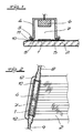
- the speed arrows of a corresponding flow profile have been drawn in FIG.
- Fig. 1 it can be seen that the conductor track 1 is in the edge region of a motor vehicle window 2, wherein a layer 10 of black ceramic is arranged under the conductor track 1, which conceals the conductor track 1 in the installed state of the motor vehicle window.
- the attachment edge 3 is provided with a soft-elastic seal 11.
- the anode 6 is made of carbon.
- the devices 8, 9 for the supply or discharge of the electrolyte are arranged opposite one another in the end faces of the electroplating chamber 4 in the exemplary embodiment. But they could also be arranged on the long sides. In Fig. 2 it can be seen that wide slot nozzles 12 are used.
- the electroplating chamber can also be rinsed via the devices 8, 9.
- the devices 8, 9 are connected to a corresponding rinsing liquid container, to which a pump is assigned, by way of redesigning. Rinsing takes place before and / or after electroplating or in an intermediate stage, depending on the electroplating requirements.
Abstract
Description
Die Erfindung bezieht sich gattungsgemäß auf eine Vorrichtung zur galvanischen Verstärkung einer langgestreckten Leiterspur auf einer Glasscheibe, insbesondere auf einer Kraftfahrzeugscheibe, wobei die Leiterspur als Kathode geschaltet ist. Bei der Leiterspur kann es sich um eine Sammelschienenspur, um eine Heizleiterspur oder um eine Leiterspur anderer Funktion handeln. Sie verläuft im allgemeinen mehr oder weniger gerade und erstreckt sich beispielsweise über die Länge des Randes einer Kraftfahrzeugscheibe.The invention generally relates to a device for the galvanic reinforcement of an elongated conductor track on a glass pane, in particular on a motor vehicle pane, the conductor track being connected as a cathode. The conductor track can be a busbar track, a heating conductor track or a conductor track of another function. It generally runs more or less straight and extends, for example, over the length of the edge of a motor vehicle window.
Bei der bekannten gattungsgemäßen Vorrichtung (JA-OS 60159194 ist die Anode ein Tampon, der mit dem Elektrolyten getränkt wird. Die Anode wird mit der Leiterspur in Berührung gebracht und gleitend über die Leiterspur bewegt. Dazu ist eine Bedienungsperson erforderlich. Diese bekannten Maßnahmen sind zunächst personalaufwendig. Sie lassen sich praktisch nicht mehr automatisieren. Sie befriedigen aber auch in funktioneller Hinsicht nicht: Die Schichtdicke der Verstärkung hängt von der Geschicklichkeit der Bedienungsperson ab, welche die als Tampon ausgeführte Anode führt. Tatsächlich ist das Tampongalvanisieren (vgl. Galvano-Technik 1982, S. 120 ff.) bei ganz anderen Aufgaben, nämlich bei der Durchführung von Reparaturarbeiten an galvanisierten Gegenständen, entstanden.In the known generic device (JA-OS 60159194, the anode is a tampon which is impregnated with the electrolyte. The anode is brought into contact with the conductor track and moved over the conductor track in a sliding manner. An operator is required for this. These known measures are initially They can practically no longer be automated, but they are also unsatisfactory from a functional point of view: the layer thickness of the reinforcement depends on the skill of the operator who guides the anode designed as a tampon. In fact, the tampon electroplating is (cf. Galvano-Technik 1982) , P. 120 ff.) For completely different tasks, namely when carrying out repair work on galvanized objects.
Für andere Zwecke, d.h. nicht für die galvanische Verstärkung einer langgestreckten Leiterspur auf einer Glasscheibe, kennt man Vorrichtungen, die eine Kammer bilden und auf den zu galvanisierenden Gegenstand aufgesetzt werden (DE-AS 1621143). Hier bilden die Kathoden die Kammerwände. Die Anode ist zumindest in ihrem unteren Teil stabförmig ausgebildet. Das führt zu eigentümlichen Potentialverhältnissen und erheblichen Stromdichtegradienten. Der Elektrolyt wird längs der Anode in die Kammer eingeführt und entsprechend auch wieder zurückgeführt. Er verläßt außerdem die Kammer und läuft neben dem Werkstück ab. Diese bekannten Maßnahmen sind für die Verstärkung einer langgestreckten Leiterspur auf einer Glasscheibe, insbesondere wenn automatisch gearbeitet werden soll, wenig brauchbar.For other purposes, ie not for the galvanic reinforcement of an elongated conductor track on a glass pane, devices are known which form a chamber and are placed on the object to be galvanized (DE-AS 1621143). Here the cathodes form the chamber walls. The anode is rod-shaped at least in its lower part. This leads to peculiar potential relationships and considerable current density gradients. The electrolyte is along the Anode inserted into the chamber and returned accordingly. It also leaves the chamber and runs alongside the workpiece. These known measures are of little use for the reinforcement of an elongated conductor track on a glass pane, in particular if work is to be carried out automatically.
Bei galvanotechnischen Prozessen muß vor und/oder nach der Abscheidung oder in Zwischenphasen auch eine Spülung mit Wasser oder einer besonderen Spülflüssigkeit durchgeführt werden. Das geschieht regelmäßig in besonderen Apparaten, was insbesondere im Rahmen einer Massenproduktion stört.In electroplating processes, rinsing with water or a special rinsing liquid must also be carried out before and / or after the deposition or in intermediate phases. This happens regularly in special equipment, which is particularly annoying in the context of mass production.
Der Erfindung liegt die Aufgabe zugrunde, eine Vorrichtung zur galvanischen Verstärkung einer langgestreckten Leiterspur auf einer Glasscheibe zu schaffen, mit der die galvanische Verstärkung weitgehend automatisch durchgeführt werden kann und bei der sichergestellt ist, daß die Verstärkung überall eine vorgebbare Dicke aufweist. Darüber hinaus soll auch die erforderliche Spülung ohne Schwierigkeiten erfolgen können.The invention has for its object to provide a device for the galvanic reinforcement of an elongated conductor track on a glass pane, with which the galvanic reinforcement can be carried out largely automatically and in which it is ensured that the reinforcement has a predetermined thickness everywhere. In addition, the necessary rinsing should also be possible without difficulty.
Zur Lösung dieser Aufgabe ist die erfindungsgemäße Vorrichtung gekennzeichnet durch eine auf die glasscheibe mit einem Aufsetzrand dichtend aufsetzbare Galvanisierkammer, die beidseits der Leiterspur einen Distanzstreifen freiläßt, eine Anode in der Galvanisierkammer, die mit einem Abstandzwischenraum über der Leiterspur angeordnet ist und der Leiterspur folgt und Einrichtungen zur Zuführung und Abführung eines Elektrolyten oder einer Spülflüssigkeit, wobei der Elektrolyt auf seinem Wege von der Zuführung zur Abführung den Abstandzwischenraum gleichmäßig durchströmt und wobei der Elektrolyt bzw. die Spülflüssigkeit in abwechselnder Folge die Galvanisierkammer durchströmen. Soll die Dicke überall gleich sein, so erstreckt sich die Anode äquidistant über der Leiterspur. Zur Erzielung unterschiedlicher Dicken kann sie auch schräg angeordnet oder gestuft bzw. abgeschrägt sein. Nach bevorzugter Ausführungsform ist der Aufsetzrand mit einer weichelastischen Dichtung versehen. Die Anode besteht zweckmäßigerweise aus Kohlenstoff, aus einem Metall mit Titanbeschichtung oder aus Edelstahl. ― In dem Merkmal, daß die Galvanisierkammer einen Aufsetzrand aufweist, vorzugsweise einen Aufsetzrand mit weichelastischer Dichtung, kommt zum Ausdruck, daß die Galvanisierkammer dichtend auf die Oberfläche der Glasscheibe aufgesetzt wird. Das gilt sowohl für Glasscheiben, die vollkommen eben ausgeführt sind, als auch für Glasscheiben, die einfach oder doppelt gekrümmt sind. Insoweit folgt die Galvanisierkammer in ihrer Ausbildung der Geometrie, die von der Glasscheibe vorgegeben ist. Es versteht sich, daß die kinematische Umkehr unter den Schutz fällt, bei der die zu behandelnden Glasscheiben auf die umgekehrt angeordnete Galvanisierkammer aufgelegt werden.To achieve this object, the device according to the invention is characterized by an electroplating chamber which can be sealingly placed on the glass pane with an attachment edge and which leaves a spacer strip free on both sides of the conductor track, an anode in the electroplating chamber which is arranged with a space between the conductor track and follows the conductor track and devices for supplying and discharging an electrolyte or a rinsing liquid, the electrolyte flowing uniformly through the spacing on its way from the supply to the discharge, and wherein the electrolyte or the rinsing liquid alternately flow through the electroplating chamber. If the thickness is to be the same everywhere, the anode extends equidistantly over the conductor track. To achieve different thicknesses, it can also be arranged obliquely or stepped or beveled. According to a preferred embodiment, the attachment edge is provided with a soft elastic seal. The anode suitably consists of carbon, a metal with a titanium coating or stainless steel. - In the feature that the electroplating chamber has a mounting edge, preferably a mounting edge with a soft elastic seal, it is expressed that the electroplating chamber is sealingly placed on the surface of the glass pane. This applies to glass panes that are completely flat as well as to glass panes that are single or double curved. In this respect, the electroplating chamber follows the geometry given by the glass pane. It goes without saying that the kinematic reversal falls under the protection in which the glass panes to be treated are placed on the electroplating chamber arranged in reverse.
Erfindungsgemäß wird auf die Glasscheibe im Bereich der zu verstärkenden Leiterspur die Galvanisierkammer aufgesetzt. Das kann automatisch oder weitgehend automatisch geschehen. Das Aufsetzen erfolgt so, daß am Aufsetzrand eine möglichst weitgehende Abdichtung erfolgt. Eine Bewegung der Anode relativ zu der als Kathode geschalteten Leiterspur findet nicht statt. Der Elektrolyt durchströmt auf seinem Weg von der Zuführung zur Abführung den Abstandzwischenraum gleichmäßig. Die Dicke der Verstärkung läßt sich leicht steuern, indem die üblichen, die Galvanotechnik der Zusammenhänge bestimmenden Parameter gesteuert werden, beispielsweise die Ionenkonzentration im Elektrolyten, die Temperatur und die Stromdichte. Da die Anode nicht in Lösung geht, wird der Elektrolyt insoweit nicht störend beeinflußt. Erfindungsgemäß ist sichergestellt, daß die Stromdichte längs der Leiterspur überall vorgebbar ist und keine störenden Gradienten aufweist. Die Spülung ist ohne besondere Manipulation der Glasscheibe möglich und erfordert keinen besonderen Apparat.According to the invention, the electroplating chamber is placed on the glass pane in the area of the conductor track to be reinforced. This can happen automatically or largely automatically. It is placed in such a way that the sealing edge is sealed as far as possible. The anode does not move relative to the conductor track connected as the cathode. The electrolyte flows evenly through the gap between the feeder and the discharge. The thickness of the reinforcement can be easily controlled by controlling the usual parameters determining the electroplating of the relationships, for example the ion concentration in the electrolyte, the temperature and the current density. Since the anode does not go into solution, the electrolyte is not adversely affected. According to the invention, it is ensured that the current density can be predetermined everywhere along the conductor track and has no disturbing gradients. The rinsing is possible without special manipulation of the glass pane and does not require any special apparatus.
Im einzelnen bestehen im Rahmen der Erfindung mehrere Möglichkeiten. Eine bevorzugte Ausführungsform der Erfindung ist dadurch gekennzeichnet, daß die Einrichtungen für die Zuführung bzw. Abführung des Elektrolyten bzw. der Spülflüssigkeit einander gegenüberliegend an den Stirnseiten der Galvanisierkammer angeordnet sind. Man kann aber auch die Einrichtungen für die Zuführung bzw. Abführung des Elektrolyten bzw. der Spülflüssigkeit einander gegenüberliegend an den Längsseiten der Galvanisierkammer anordnen. Um auf einfache Weise zu erreichen, daß das Strömungsprofil des Elektrolyten über der Leiterspur überall die gleiche Elektrolytgeschwindigkeit aufweist, wird zweckmäßigerweise, auch bei der Spülung, mit Breitschlitzdüsen gearbeitet. Im übrigen empfiehlt es sich, die erfindungsgemäße Vorrichtung auf die Leiterspur so aufzusetzen, daß der Distanzstreifen zu beiden Seiten der Leiterspur die gleiche Breite besitzt. Das hat zur Folge, daß die Begrenzung der Galvanisierkammer, die als Randbedingung das Strömungsprofil beeinflußt, im Bereich der Leiterspur sich nicht störend auswirkt. Die Strömung kann laminar oder turbulent eingerichtet werden.There are several options within the scope of the invention. A preferred embodiment of the invention is characterized in that the devices for supplying or discharging the electrolyte or the rinsing liquid are arranged opposite one another on the end faces of the electroplating chamber. However, the devices for supplying or discharging the electrolyte or the rinsing liquid can also be arranged opposite one another on the long sides of the electroplating chamber. In order to achieve in a simple manner that the flow profile of the electrolyte over the conductor track has the same electrolyte speed everywhere, it is expedient to work with wide-slot nozzles, even during the flushing. For the rest, it is advisable to place the device according to the invention on the conductor track so that the spacer strip has the same width on both sides of the conductor track. The result of this is that the limitation of the electroplating chamber, which influences the flow profile as a boundary condition, does not have a disruptive effect in the region of the conductor track. The flow can be laminar or turbulent.
Die erreichten Vorteile sind darin zu sehen, daß mit der erfindungsgemäßen Vorrichtung vollautomatisch oder weitgehend automatisch die Verstärkung einer langgestreckten Leiterspur auf einer Glasscheibe erreicht werden kann und zwar bei vorgebbarer Dicke der Verstärkung, die im übrigen auch einfach gesteuert werden kann, sowie mit einfacher Spülung.The advantages achieved can be seen in the fact that with the device according to the invention the reinforcement of an elongated conductor track is fully automatic or largely automatic can be achieved on a glass pane and that with a predeterminable thickness of the reinforcement, which can also be easily controlled, as well as with simple rinsing.
Im folgenden wird die Erfindung anhand einer lediglich ein Ausführungsbeispiel darstellenden Zeichnung ausführlicher erläutert. Es zeigen in schematischer Darstellung
- Fig. 1
- einen Querschnitt durch eine erfindungsgemäße Vorrichtung in Arbeitsstellung,
- Fig. 2
- in gegenüber der Fig. 1 verkleinertem Maßstab, eine Draufsicht auf den Gegenstand der Fig. 1.
In the following, the invention will be explained in more detail with reference to a drawing showing only one embodiment. They show a schematic representation
- Fig. 1
- 3 shows a cross section through a device according to the invention in the working position,
- Fig. 2
- on a smaller scale compared to FIG. 1, a top view of the object of FIG. 1.
Die in den Figuren dargestellte Vorrichtung dient zu galvanischen Verstärkung einer langgestreckten Leiterspur 1 auf einer Glasscheibe 2, im Ausführungsbeispiel auf einer Kraftfahrzeugscheibe. Die Leiterspur 1 ist als Kathode geschaltet. Es mag sich um die Leiterspur 1 für eine Sammelschiene handeln.The device shown in the figures is used for galvanic reinforcement of an elongated conductor track 1 on a
Die Vorrichtung besteht aus einer auf die Glasscheibe 2 mit einem Aufsetzrand 3 dichtend aufsetzbare Galvanisierkammer 4, die beidseits der Leiterspur 1 einen Distanzstreifen 5 freiläßt. Dazu wird insbesondere auf die Fig. 1 verwiesen. Zur Vorrichtung gehört fernerhin eine Anode 6 in der Galvanisierkammer 4, die mit einem Abstandzwischenraum 7 über der Leiterspur 1 äquidistant angeordnet ist und der Leiterspur 1 folgt. Außerdem sind Einrichtungen 8, 9 zur Zuführung und Abführung des Elektrolyten vorgesehen. Die Anordnung ist insgesamt so getroffen, daß der Elektrolyt auf seinem Wege von der Zuführung 8 zur Abführung 9 den Abstandzwischenraum 7 gleichmäßig durchströmt. In Fig. 2 wurden die Geschwindigkeitspfeile eines entsprechenden Strömungsprofils eingezeichnet.The device consists of an
In der Fig. 1 erkennt man, daß sich die Leiterspur 1 im Randbereich einer Kraftfahrzeugscheibe 2 befindet, wobei unter der Leiterspur 1 eine Schicht 10 aus schwarzer Keramik angeordnet ist, die die Leiterspur 1 im eingebauten Zustand der Kraftfahrzeugscheibe kaschiert.In Fig. 1 it can be seen that the conductor track 1 is in the edge region of a
Im Ausführungsbeispiel und nach bevorzugter Ausführungsform der Erfindung ist der Aufsetzrand 3 mit einer weichelastischen Dichtung 11 versehen. Die Anode 6 besteht aus Kohlenstoff.In the exemplary embodiment and according to a preferred embodiment of the invention, the
Die Einrichtungen 8, 9 für die Zuführung bzw. Abführung des Elektrolyten sind im Ausführungsbeispiel einander gegenüberliegend in den Stirnseiten der Galvanisierkammer 4 angeordnet. Sie könnten aber auch an den Längsseiten angeordnet sein. In der Fig. 2 erkennt man, daß mit Breitschlitzdüsen 12 gearbeitet wird. Über die Einrichtungen 8, 9 kann auch die Spülung der Galvanisierkammer erfolgen. Die Einrichtungen 8, 9 werden dazu im Wege des Umgestaltens an einen entsprechenden Spülflüssigkeitsbehälter, dem eine Pumpe zugeordnet ist, angeschlossen. Das Spülen erfolgt vor und/oder nach dem Galvanisieren oder in einer Zwischenstufe, je nach den galvanotechnischen Erfordernissen.The
Claims (6)
Priority Applications (1)
| Application Number | Priority Date | Filing Date | Title |
|---|---|---|---|
| AT88117713T ATE68215T1 (en) | 1987-10-27 | 1988-10-25 | DEVICE FOR GALVANIC AMPLIFICATION OF A CONDUCTOR TRACK ON A GLASS PANE. |
Applications Claiming Priority (2)
| Application Number | Priority Date | Filing Date | Title |
|---|---|---|---|
| DE19873736240 DE3736240A1 (en) | 1987-10-27 | 1987-10-27 | DEVICE FOR THE GALVANIC REINFORCEMENT OF A LEAD TRACK ON A GLASS DISC |
| DE3736240 | 1987-10-27 |
Publications (2)
| Publication Number | Publication Date |
|---|---|
| EP0314053A1 EP0314053A1 (en) | 1989-05-03 |
| EP0314053B1 true EP0314053B1 (en) | 1991-10-09 |
Family
ID=6339117
Family Applications (1)
| Application Number | Title | Priority Date | Filing Date |
|---|---|---|---|
| EP88117713A Expired - Lifetime EP0314053B1 (en) | 1987-10-27 | 1988-10-25 | Electroplating device for the thickening of a conductive line on a glass window |
Country Status (6)
| Country | Link |
|---|---|
| US (1) | US4869798A (en) |
| EP (1) | EP0314053B1 (en) |
| JP (1) | JPH0647750B2 (en) |
| AT (1) | ATE68215T1 (en) |
| DE (2) | DE3736240A1 (en) |
| ES (1) | ES2026239T3 (en) |
Families Citing this family (5)
| Publication number | Priority date | Publication date | Assignee | Title |
|---|---|---|---|---|
| SE467976B (en) * | 1991-02-20 | 1992-10-12 | Dcm Innovation Ab | DEVICE FOR ELECTRICAL PLATING, IN THE MANUFACTURE OF MATRISTS FOR THE MANUFACTURE OF EX EX CDS AND PROCEDURES FOR THE MANUFACTURE OF MATRICES BY THE DEVICE |
| US5685970A (en) | 1992-07-01 | 1997-11-11 | Gould Electronics Inc. | Method and apparatus for sequentially metalized polymeric films and products made thereby |
| CN1034522C (en) * | 1995-04-18 | 1997-04-09 | 哈尔滨环亚微弧技术有限公司 | Plasma-reinforced electrochemical process for surface ceramicification and relevant product |
| JPH09307329A (en) * | 1996-05-14 | 1997-11-28 | Casio Comput Co Ltd | Antenna, its manufacture and electronic device or electric watch provided with the antenna |
| US6660155B2 (en) * | 2001-11-27 | 2003-12-09 | Korea Houghton Corporation | Process of surface coating glass panels |
Family Cites Families (15)
| Publication number | Priority date | Publication date | Assignee | Title |
|---|---|---|---|---|
| US1771680A (en) * | 1927-03-29 | 1930-07-29 | Ishisaka Sansaku | Apparatus for electroplating |
| US2135873A (en) * | 1934-11-22 | 1938-11-08 | Bausch & Lomb | Process of making metal reflectors |
| US2750332A (en) * | 1952-06-04 | 1956-06-12 | Pittsburgh Plate Glass Co | Method and apparatus for electrodeposition of a layer of uniform thickness on a conductive surface |
| GB1145367A (en) * | 1964-11-09 | 1969-03-12 | Saint Gobain | Improvements in or relating to heatable windows, more especially for vehicles |
| US3468785A (en) * | 1966-06-21 | 1969-09-23 | Photocircuits Corp | Apparatus for electroplating selected areas |
| DE1807481C3 (en) * | 1968-11-07 | 1975-10-09 | Messerschmitt-Boelkow-Blohm Gmbh, 8000 Muenchen | Partial electroplating process |
| FR2135452A1 (en) * | 1971-05-05 | 1972-12-22 | Honeywell Bull | Jointing small electric conductors - by electrolytic deposition of metals |
| JPS5238970B2 (en) * | 1971-12-25 | 1977-10-01 | ||
| JPS5512119B2 (en) * | 1974-03-12 | 1980-03-29 | ||
| CH613880A5 (en) * | 1975-09-29 | 1979-10-31 | Emile Steiger | |
| LU80496A1 (en) * | 1978-11-09 | 1980-06-05 | Cockerill | METHOD AND DIOPOSITIVE FOR THE CONTINUOUS ELECTROLYTIC DEPOSITION AT HIGH CURRENT DENSITY OF A COATING METAL ON A SHEET |
| DD143245B1 (en) * | 1979-04-25 | 1982-12-15 | Guenther Goermar | METHOD FOR PRODUCING ELECTRICALLY HEATABLE GLASS PANES |
| FR2592895B1 (en) * | 1986-01-16 | 1990-11-16 | Selectrons France | INSTALLATION FOR PERFORMING LOCALIZED ELECTROLYTIC TREATMENTS OF SURFACES. |
| DE3611833A1 (en) * | 1986-04-08 | 1987-10-15 | Schreiber P Metallisierwerk | DEVICE FOR SURFACE COATING, PARTICULARLY TREATMENT OF DAMAGED SURFACES OF METAL OR NON-METAL WORKPIECES |
| US4750981A (en) * | 1986-09-30 | 1988-06-14 | The Boeing Company | Apparatus for electroplating limited surfaces on a workpiece |
-
1987
- 1987-10-27 DE DE19873736240 patent/DE3736240A1/en active Granted
-
1988
- 1988-10-25 EP EP88117713A patent/EP0314053B1/en not_active Expired - Lifetime
- 1988-10-25 AT AT88117713T patent/ATE68215T1/en not_active IP Right Cessation
- 1988-10-25 DE DE8888117713T patent/DE3865414D1/en not_active Expired - Lifetime
- 1988-10-25 ES ES198888117713T patent/ES2026239T3/en not_active Expired - Lifetime
- 1988-10-26 US US07/262,929 patent/US4869798A/en not_active Expired - Fee Related
- 1988-10-26 JP JP63268368A patent/JPH0647750B2/en not_active Expired - Lifetime
Also Published As
| Publication number | Publication date |
|---|---|
| US4869798A (en) | 1989-09-26 |
| DE3736240A1 (en) | 1989-05-11 |
| JPH01212792A (en) | 1989-08-25 |
| ES2026239T3 (en) | 1992-04-16 |
| EP0314053A1 (en) | 1989-05-03 |
| ATE68215T1 (en) | 1991-10-15 |
| DE3865414D1 (en) | 1991-11-14 |
| DE3736240C2 (en) | 1989-09-14 |
| JPH0647750B2 (en) | 1994-06-22 |
Similar Documents
| Publication | Publication Date | Title |
|---|---|---|
| DE3236545A1 (en) | METHOD FOR ELECTROPLATING AND DEVICE FOR CARRYING OUT THE METHOD | |
| EP1712660A1 (en) | Insoluble anode | |
| DE3246690C2 (en) | ||
| EP0314053B1 (en) | Electroplating device for the thickening of a conductive line on a glass window | |
| DE3017079A1 (en) | DEVICE FOR ELECTROPLATING | |
| DE3127390A1 (en) | GALVANIZING DEVICE | |
| DE3723745C1 (en) | Process and device for breaking emulsions | |
| DE3325316A1 (en) | Metal-coating process and device, in particular for copper-plating cylindrical bodies | |
| DE60104107T2 (en) | METHOD AND DEVICE FOR ELECTROLYTIC COATING OF A METAL STRIP | |
| DE3901807A1 (en) | DEVICE FOR ELECTROLYTICALLY DEPOSITING METALS ON ONE OR BOTH SIDES OF TAPES | |
| DE10215463C1 (en) | Continuous plant for electrolytic metallization of printed circuit boards, includes precautions reducing electrical potential between adjacent workpieces | |
| EP0162440A2 (en) | Method and device for electrochemically machining very narrow grooves | |
| DE1621097A1 (en) | Method and device for the electrolytic production of elongated metal objects, in particular of wires | |
| DE3011005A1 (en) | Continuous electroplating of steel strip on one or both sides - using anode box with perforated base and strip cathode and electrolyte which is continuously recirculated | |
| EP0032892B1 (en) | Device for producing electrolytically coated wires | |
| DE3024696C2 (en) | Electrolysis cell for carrying out refining electrolysis | |
| DE1954024A1 (en) | Process and device for the surface treatment of glass objects | |
| WO1995021952A1 (en) | Process and device for the electrolytic surface coating of workpieces | |
| DE3206457C2 (en) | ||
| DE2548212C3 (en) | Method and device for resistance heating of electrically conductive workpieces | |
| DE2534918C3 (en) | Device for electrocoating | |
| DE4437848C1 (en) | Appts. for continuously electroplating plane workpieces | |
| DE2322356A1 (en) | PROCESS AND DEVICE FOR CONTINUOUSLY COVERING A STRIP OF ALUMINUM OR ALUMINUM ALLOY WITH A SOFT SOLDER | |
| DE496225C (en) | Arrangement to achieve galvanic metal deposits on profile bars | |
| DE2125420A1 (en) | Holder for electrochemical machining processes |
Legal Events
| Date | Code | Title | Description |
|---|---|---|---|
| PUAI | Public reference made under article 153(3) epc to a published international application that has entered the european phase |
Free format text: ORIGINAL CODE: 0009012 |
|
| AK | Designated contracting states |
Kind code of ref document: A1 Designated state(s): AT BE CH DE ES FR GB IT LI SE |
|
| 17P | Request for examination filed |
Effective date: 19890602 |
|
| 17Q | First examination report despatched |
Effective date: 19910301 |
|
| GRAA | (expected) grant |
Free format text: ORIGINAL CODE: 0009210 |
|
| AK | Designated contracting states |
Kind code of ref document: B1 Designated state(s): AT BE CH DE ES FR GB IT LI SE |
|
| REF | Corresponds to: |
Ref document number: 68215 Country of ref document: AT Date of ref document: 19911015 Kind code of ref document: T |
|
| ITF | It: translation for a ep patent filed |
Owner name: ING. A. GIAMBROCONO & C. S.R.L. |
|
| REF | Corresponds to: |
Ref document number: 3865414 Country of ref document: DE Date of ref document: 19911114 |
|
| GBT | Gb: translation of ep patent filed (gb section 77(6)(a)/1977) | ||
| ET | Fr: translation filed | ||
| REG | Reference to a national code |
Ref country code: ES Ref legal event code: FG2A Ref document number: 2026239 Country of ref document: ES Kind code of ref document: T3 |
|
| PLBE | No opposition filed within time limit |
Free format text: ORIGINAL CODE: 0009261 |
|
| STAA | Information on the status of an ep patent application or granted ep patent |
Free format text: STATUS: NO OPPOSITION FILED WITHIN TIME LIMIT |
|
| 26N | No opposition filed | ||
| EAL | Se: european patent in force in sweden |
Ref document number: 88117713.3 |
|
| PGFP | Annual fee paid to national office [announced via postgrant information from national office to epo] |
Ref country code: AT Payment date: 19951023 Year of fee payment: 8 |
|
| PGFP | Annual fee paid to national office [announced via postgrant information from national office to epo] |
Ref country code: CH Payment date: 19951024 Year of fee payment: 8 |
|
| PGFP | Annual fee paid to national office [announced via postgrant information from national office to epo] |
Ref country code: FR Payment date: 19961011 Year of fee payment: 9 |
|
| PGFP | Annual fee paid to national office [announced via postgrant information from national office to epo] |
Ref country code: SE Payment date: 19961018 Year of fee payment: 9 Ref country code: BE Payment date: 19961018 Year of fee payment: 9 |
|
| PGFP | Annual fee paid to national office [announced via postgrant information from national office to epo] |
Ref country code: GB Payment date: 19961019 Year of fee payment: 9 |
|
| PG25 | Lapsed in a contracting state [announced via postgrant information from national office to epo] |
Ref country code: AT Effective date: 19961025 |
|
| PG25 | Lapsed in a contracting state [announced via postgrant information from national office to epo] |
Ref country code: LI Effective date: 19961031 Ref country code: CH Effective date: 19961031 |
|
| PGFP | Annual fee paid to national office [announced via postgrant information from national office to epo] |
Ref country code: ES Payment date: 19961031 Year of fee payment: 9 |
|
| REG | Reference to a national code |
Ref country code: CH Ref legal event code: PL |
|
| PGFP | Annual fee paid to national office [announced via postgrant information from national office to epo] |
Ref country code: DE Payment date: 19970927 Year of fee payment: 10 |
|
| PG25 | Lapsed in a contracting state [announced via postgrant information from national office to epo] |
Ref country code: GB Free format text: LAPSE BECAUSE OF NON-PAYMENT OF DUE FEES Effective date: 19971025 |
|
| PG25 | Lapsed in a contracting state [announced via postgrant information from national office to epo] |
Ref country code: SE Free format text: LAPSE BECAUSE OF NON-PAYMENT OF DUE FEES Effective date: 19971026 |
|
| PG25 | Lapsed in a contracting state [announced via postgrant information from national office to epo] |
Ref country code: ES Free format text: LAPSE BECAUSE OF EXPIRATION OF PROTECTION Effective date: 19971027 |
|
| PG25 | Lapsed in a contracting state [announced via postgrant information from national office to epo] |
Ref country code: FR Free format text: THE PATENT HAS BEEN ANNULLED BY A DECISION OF A NATIONAL AUTHORITY Effective date: 19971031 Ref country code: BE Free format text: LAPSE BECAUSE OF NON-PAYMENT OF DUE FEES Effective date: 19971031 |
|
| BERE | Be: lapsed |
Owner name: FLACHGLAS A.G. Effective date: 19971031 |
|
| GBPC | Gb: european patent ceased through non-payment of renewal fee |
Effective date: 19971025 |
|
| EUG | Se: european patent has lapsed |
Ref document number: 88117713.3 |
|
| REG | Reference to a national code |
Ref country code: FR Ref legal event code: ST |
|
| PG25 | Lapsed in a contracting state [announced via postgrant information from national office to epo] |
Ref country code: DE Free format text: LAPSE BECAUSE OF NON-PAYMENT OF DUE FEES Effective date: 19990803 |
|
| REG | Reference to a national code |
Ref country code: ES Ref legal event code: FD2A Effective date: 20010201 |
|
| PG25 | Lapsed in a contracting state [announced via postgrant information from national office to epo] |
Ref country code: IT Free format text: LAPSE BECAUSE OF NON-PAYMENT OF DUE FEES;WARNING: LAPSES OF ITALIAN PATENTS WITH EFFECTIVE DATE BEFORE 2007 MAY HAVE OCCURRED AT ANY TIME BEFORE 2007. THE CORRECT EFFECTIVE DATE MAY BE DIFFERENT FROM THE ONE RECORDED. Effective date: 20051025 |