EP0313429B2 - Bandsägemaschine - Google Patents
Bandsägemaschine Download PDFInfo
- Publication number
- EP0313429B2 EP0313429B2 EP88402507A EP88402507A EP0313429B2 EP 0313429 B2 EP0313429 B2 EP 0313429B2 EP 88402507 A EP88402507 A EP 88402507A EP 88402507 A EP88402507 A EP 88402507A EP 0313429 B2 EP0313429 B2 EP 0313429B2
- Authority
- EP
- European Patent Office
- Prior art keywords
- saw band
- driving
- flywheel
- valve
- hydraulic
- Prior art date
- Legal status (The legal status is an assumption and is not a legal conclusion. Google has not performed a legal analysis and makes no representation as to the accuracy of the status listed.)
- Expired - Lifetime
Links
Images
Classifications
-
- B—PERFORMING OPERATIONS; TRANSPORTING
- B23—MACHINE TOOLS; METAL-WORKING NOT OTHERWISE PROVIDED FOR
- B23D—PLANING; SLOTTING; SHEARING; BROACHING; SAWING; FILING; SCRAPING; LIKE OPERATIONS FOR WORKING METAL BY REMOVING MATERIAL, NOT OTHERWISE PROVIDED FOR
- B23D55/00—Sawing machines or sawing devices working with strap saw blades, characterised only by constructional features of particular parts
- B23D55/08—Sawing machines or sawing devices working with strap saw blades, characterised only by constructional features of particular parts of devices for guiding or feeding strap saw blades
- B23D55/088—Devices for feeding strap saw blades
- B23D55/089—Devices for feeding strap saw blades with fluid regulating means for in-feed
-
- B—PERFORMING OPERATIONS; TRANSPORTING
- B23—MACHINE TOOLS; METAL-WORKING NOT OTHERWISE PROVIDED FOR
- B23D—PLANING; SLOTTING; SHEARING; BROACHING; SAWING; FILING; SCRAPING; LIKE OPERATIONS FOR WORKING METAL BY REMOVING MATERIAL, NOT OTHERWISE PROVIDED FOR
- B23D55/00—Sawing machines or sawing devices working with strap saw blades, characterised only by constructional features of particular parts
- B23D55/06—Sawing machines or sawing devices working with strap saw blades, characterised only by constructional features of particular parts of drives for strap saw blades; of wheel mountings
-
- B—PERFORMING OPERATIONS; TRANSPORTING
- B23—MACHINE TOOLS; METAL-WORKING NOT OTHERWISE PROVIDED FOR
- B23Q—DETAILS, COMPONENTS, OR ACCESSORIES FOR MACHINE TOOLS, e.g. ARRANGEMENTS FOR COPYING OR CONTROLLING; MACHINE TOOLS IN GENERAL CHARACTERISED BY THE CONSTRUCTION OF PARTICULAR DETAILS OR COMPONENTS; COMBINATIONS OR ASSOCIATIONS OF METAL-WORKING MACHINES, NOT DIRECTED TO A PARTICULAR RESULT
- B23Q11/00—Accessories fitted to machine tools for keeping tools or parts of the machine in good working condition or for cooling work; Safety devices specially combined with or arranged in, or specially adapted for use in connection with, machine tools
- B23Q11/04—Arrangements preventing overload of tools, e.g. restricting load
-
- Y—GENERAL TAGGING OF NEW TECHNOLOGICAL DEVELOPMENTS; GENERAL TAGGING OF CROSS-SECTIONAL TECHNOLOGIES SPANNING OVER SEVERAL SECTIONS OF THE IPC; TECHNICAL SUBJECTS COVERED BY FORMER USPC CROSS-REFERENCE ART COLLECTIONS [XRACs] AND DIGESTS
- Y10—TECHNICAL SUBJECTS COVERED BY FORMER USPC
- Y10T—TECHNICAL SUBJECTS COVERED BY FORMER US CLASSIFICATION
- Y10T83/00—Cutting
- Y10T83/141—With means to monitor and control operation [e.g., self-regulating means]
-
- Y—GENERAL TAGGING OF NEW TECHNOLOGICAL DEVELOPMENTS; GENERAL TAGGING OF CROSS-SECTIONAL TECHNOLOGIES SPANNING OVER SEVERAL SECTIONS OF THE IPC; TECHNICAL SUBJECTS COVERED BY FORMER USPC CROSS-REFERENCE ART COLLECTIONS [XRACs] AND DIGESTS
- Y10—TECHNICAL SUBJECTS COVERED BY FORMER USPC
- Y10T—TECHNICAL SUBJECTS COVERED BY FORMER US CLASSIFICATION
- Y10T83/00—Cutting
- Y10T83/707—By endless band or chain knife
- Y10T83/7101—With tool in-feed
- Y10T83/7133—By gravity
- Y10T83/7139—With fluid in-feed regulating means
Definitions
- the present invention relates to band sawing machines which are intended to be used for sawing metal parts, such as metal bars or the like.
- these comprise a mobile working assembly disposed above the location provided for the workpiece, this assembly comprising the saw band and its drive device.
- This assembly comprising the saw band and its drive device.
- the penetration of the saw band is effected by the vertical displacement of the working assembly under the action of its sole weight.
- this movement which determines the speed of penetration of the saw band, is braked by a hydraulic device comprising a leakage circuit provided with a flow rate regulator.
- patent FR 2,556,258 describes a sawing machine in which there is provided a feeler disposed in contact with the back of the saw band and which is capable of acting on a device causing the descent of the assembly to stop mobile in the event that the force exerted on this probe exceeds a determined load.
- an intermediate element capable of ensuring a modification of the conditions of action of the probe on the stop member of the mobile assembly, as a function of the width of the workpiece.
- the subject of the present invention is a sawing machine comprising a regulating system of very simple design and which is capable of automatically ensuring satisfactory operating safety in the event of an increase in the resistance opposed to the driving of the sawing tape.
- This band sawing machine comprises, opposite the location provided for the workpiece to be sawn, an assembly comprising the saw band and its drive device which assembly is movable towards the workpiece at its speed displacement braked by a hydraulic circuit comprising a valve capable of limiting, or even possibly interrupting, the flow of the flow characterized in that opposite the valve there is provided a non-electronic and / or non-electronic control member electric which is associated with the means - mechanical, hydraulic or other - of actuation of the saw band drive wheel so as to be able to act on the corresponding valve of the hydraulic braking circuit in the event of an increase in resistance opposing the drive torque of the saw band, so that such an increase causes a limitation of the flow rate in the hydraulic braking circuit, and consequently a reduction in the speed of movement of the mobile working assembly.
- the saw band drive wheel is rotated by a drive member acting on it by means of an adjustable tension spring, the limitation valve of the flow in the hydraulic braking circuit being arranged so as to be actuated by this drive member, in the event that the resistance opposed to the drive torque exceeds the value for which the spring is adjusted.
- This embodiment is particularly suitable in the case where the saw blade drive wheel is driven by an electric motor.
- this drive can also be provided by a hydraulic motor, in which case provision is made, on the supply circuit of this motor, for a bypass leading to a jack arranged opposite the flow limitation valve provided in the hydraulic braking circuit. the speed of movement of the mobile working assembly.
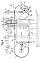
- the sawing machine shown in Figures 1 to 3 is of the type in which the saw band is arranged horizontally in its working area. At the location provided for the workpiece, this machine comprises an immobilizing vice comprising two fixed jaws 1 and two movable jaws 2. The latter are mounted on slides (not shown), which makes it possible to adjust their position in depending on the width of the workpiece.
- a mobile working assembly designated by the general reference 3, which comprises the saw band 4 and its drive device, in this case a drive wheel 5 and a flywheel 6 return and tension.
- These two flywheels are arranged in the same vertical plane on either side of two vertical columns 7 forming part of the frame and on which slides the mobile working assembly 3.
- the tensioning flywheel 6 is slidably mounted on a horizontal slide and a hydraulic cylinder 6a acts on the latter to ensure the tensioning of the saw band 4.
- the flywheel 5 it is rotated by means of a particular device which will be described in detail below.
- the arrangement is such that the mobile working assembly 3 slides freely on the two columns 7 so that its descent takes place under the effect of its weight alone.
- this movement is braked by a hydraulic device comprising a fixed piston 8 housed inside a cylinder 9 secured to the chassis of the mobile assembly 3.
- the upper part of this cylinder is filled with oil and the latter is found expelled from this cylinder during the descent of the mobile assembly 3 according to arrow F.
- the fluid is evacuated through the leakage pipe 10 connected to the upper end of the cylinder 9 and which leads to a reservoir 11 via another pipe 12.
- this comprises a member 13 for adjusting the flow rate. It is therefore this member which determines the extent of braking of the mobile assembly 3, and consequently the speed of its downward movement.
- a safety system capable of causing the mobile assembly 3 to stop in the event of ribbon overload.
- This system comprises a device 14 for closing the hydraulic braking circuit, which is connected to the pipe 12.
- This device is capable of being actuated by a vertical rod 15, the lower end of which carries a probe 16 located in contact with the back of the saw band 4.
- This rod is carried by a vertical arm 17, the end of which constitutes one of the guides of the saw band.
- an intermediate element is interposed between the device 14 forming a valve and the upper end of the sliding rod 15 in order to modify the conditions of actuation of the probe as a function the width of the workpiece.
- This intermediate element consists of the free end of a horizontal bar 18 fixed cantilevered on the upper end of a vertical arm 19, the lower end of which constitutes the second guide member for the saw band 4
- this second vertical arm is mounted movable in the transverse direction on the chassis of the movable assembly 3 and it is subjected to the action of elastic thrust means (not shown) which hold it in place against the movable jaws 2 of the clamping vice.
- the position of this vertical arm 19 is directly a function of the width of the workpiece. It is therefore the same for the horizontal bar 18.
- this comprises a ramp constituting a cam whose profile is capable of ensuring a modification of the conditions of actuation of the probe 16 on the shutter valve 14 as a function of the width of the workpiece.
- the system thus formed is able to provide the desired security in the event of an increase in the resistance opposed to the penetration of the saw band into the workpiece.
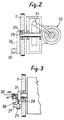
- the present machine is equipped with a self-regulating system intended to come into action in the event of an increase in the resistance opposed to the driving of the sawing tape, which is a completely different phenomenon. that of an increase in the resistance to penetration of the saw band into the material of the workpiece.
- This self-regulating system is designed to act on the braking circuit of the mobile assembly 3 so as to ensure the reduction of the descent speed, in the event that there is an excessive increase in the resistance opposed to driving the saw band 4.
- This self-regulating system comprises a valve 20 inserted in a pipe 21 which ensures the connection of the pipe 10 for output from the cylinder 9 with the pipe 12 leading to the reservoir 11.
- This valve is suitable to ensure the reduction of the flow rate or even possibly the stopping thereof.
- this valve is controlled by means sensitive to an increase in resistance opposing the drive torque of the saw band 4.
- the drive wheel 5 of the saw band is driven from an electric motor 22. This is coupled to a motor shaft 23 by means of a system coupling 24 with worm and tangent wheel. But the drive wheel 5 is not directly coupled in rotation with the drive shaft 23, because it is free relative to the latter due to its mounting on bearings 25 provided around this shaft.
- the rotary drive of the steering wheel 5 is ensured by means of a radial arm 26 carried by the free end of the shaft 23 and which is arranged opposite one of the faces of this flywheel.
- the free end of this arm is supported on a stop 27 carried by flywheel 5, which ensures the rotational drive thereof.
- the radial arm 26 does not bear directly on the stop 27, but by means of a spring 28, the initial tension of which is adjustable by the operation of a screw 29.
- the body of the safety valve 20 is itself even fixed on the radial arm 26 opposite a pusher 30 carried by the stop 27, or directly by the flywheel 5.
- the connection of the body of the valve 20 to the hydraulic circuit is ensured by a rotary connector (not shown).
- the radial arm 26 drives the flywheel 5 as long as normal resistance opposes the drive torque of the saw band 4.
- the spring 28 is caused to give way, which causes the valve 20 to be actuated by the pusher 30 carried by the stopper 27. Consequently there is a reduction in the flow rate in the pipe 21 , and consequently a reduction in the speed of descent of the mobile working assembly 3.
- the screw 29 makes it possible to adjust at will the conditions under which the valve 20 is actuated.
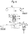
- FIG. 4 illustrates the hydraulic operating diagram provided in another embodiment of the sawing machine according to the invention. This is a particular embodiment in which the saw blade drive wheel is driven by a hydraulic motor 31, and no longer by an electric motor as in the embodiment described above.
- a valve 20a intended to reduce the flow rate, or even to stop it, in the event of an abnormal increase in the resistance to the movement of the saw band 4.
- the hydraulic circuit 32 for supplying the hydraulic motor 31 comprises a bypass 33 leading to a jack 34.
- the rod 35 of the piston 36 thereof is arranged opposite a regulating valve 20a of so as to activate the latter when an increase occurs pressure in the supply circuit 32 of the motor 31, therefore when an abnormal increase occurs in the resistance opposed to the running of the saw band.
- the machine according to the invention has the advantage that an abnormal increase in the resistance opposed to the movement of the saw band automatically results in a reduction in the speed of movement of the mobile working assembly.
- this safety and regulation system has the additional advantage of being able to be combined with the safety device operating under the effect of an overload undergone by this same tape, as is the case for the machine according to the figures. 1 to 3. A perfect operating safety of the sawing machine thus equipped is therefore obtained.
- the sawing machine according to the invention could very well comprise only the only self-regulating system intervening in the event of an increase. resistance oppose the advancement of the saw band.
- the sawing machine according to the invention is not necessarily of the horizontal band type. Indeed the saw band can very well be arranged vertically opposite the immobilization vice of the workpiece. The movement of the mobile assembly is then ensured by hydraulic pressure, and the speed of movement is braked by the same safety device as that described above.
Landscapes
- Engineering & Computer Science (AREA)
- Mechanical Engineering (AREA)
- Sawing (AREA)
Claims (4)
- Bandsägemaschine mit einer relativ zur Stelle an dem zu sägenden Werkstück gegenüberliegenden Einheit (3), mit dem Bandsägeblatt (4) und seinem Antrieb, wobei die Einheit (3) in Richtung auf das Werkstück beweglich vorgesehen ist und die Bewegungsgeschwindigkeit durch einen Hydraulikkreis (10, 12, 21) mit einem Ventil (20, 20a) zum Begrenzen oder sogar Unterbrechen des Durchflusses abgebremst wird, dadurch gekennzeichnet, daß ein relativ zu dem Ventil (20, 20a) gegenüberliegendes Steuerorgan (30) aus einer nicht elektronischen und/oder nicht elektrischen stur in Verbindung mit mechanischen, hydraulischen oder anderen Mitteln für die Betätigung des Antriebsrads (5) des Bandsägeblatts (4) vorgesehen ist, um auf das entsprechende Ventil (20, 20a) des hydraulischen Bremskreises bei einem Anstieg des Widerstands gegensätzlich auf das Antriebsmoment des Bandsägeblatts (4) in der Weise einzuwirken, daß ein solcher Anstieg eine Begrenzung des Durchflusses in dem hydraulischen Bremskreis hervorruft, damit eine Verringerung der Bewegungsgeschwindigkeit der beweglichen Einheit (3) eintritt.
- Bandsägemaschine nach Anspruch 1, dadurch gekennzeichnet, daß das Antriebsrad (5) des Bandsägeblatts (4) über ein Antriebsorgan (26) angetrieben ist, das unter Zwischenschaltung einer in ihrer Spannung einstellbaren Feder (28) darauf einwirkt, und daß das Ventil (20) zur Begrenzung des Durchflusses in dem hydraulischen Bremskreis so angeordnet ist, daß es durch das Antriebsorgan betätigt wird, und zwar, wenn der dem Antriebsmoment entgegengerichtete Widerstand den an der Feder (28) eingestellten Wert übersteigt.
- Bandsägemaschine nach Anspruch 2, dadurch gekennzeichnet, daß das Antriebsrad (5) des Bandsägeblatts (4) frei drehbar auf seiner Antriebswelle (23) gelagert ist, und diese einen radialen Arm (26) trägt, der unter Zwischenschaltung einer in ihrer Spannung einstellbaren Feder (28) auf einen festen Anschlag (27) einwirkt, der auf dem Antriebsrad vorgesehen ist, und daß das Ventil (20) zur Begrenzung des Durchflusses auf dem radialen Arm (26) angeordnet und über ein auf dem Antriebsrad (5) des Bandsägeblatts angeordnetes Betätigungsorgan (30) betätigbar ist.
- Bandsägemaschine nach Anspruch 1, dadurch gekennzeichnet, daß in Verbindung mit dem über einen Hydraulikmotor (31) angetriebenen Antriebsrad (5) des Bandsägeblatts (4) in der Zuflußleitung (32) zu diesem Hydraulikmotor eine Abzweigleitung (33) vorgesehen ist, die zu einem Hydraulikzylinder (34) führt, der relativ zu dem Ventil (20a) für die Begrenzung des Durchflusses in dem hydraulischen Bremskreis für die Bewegungsgeschwindigkeit der beweglichen Einheit gegenüberliegend angeordnet ist.
Applications Claiming Priority (2)
| Application Number | Priority Date | Filing Date | Title |
|---|---|---|---|
| FR8714438A FR2621842B1 (fr) | 1987-10-20 | 1987-10-20 | Machine a scier a ruban |
| FR8714438 | 1987-10-20 |
Publications (3)
| Publication Number | Publication Date |
|---|---|
| EP0313429A1 EP0313429A1 (de) | 1989-04-26 |
| EP0313429B1 EP0313429B1 (de) | 1992-01-02 |
| EP0313429B2 true EP0313429B2 (de) | 1995-03-22 |
Family
ID=9355965
Family Applications (1)
| Application Number | Title | Priority Date | Filing Date |
|---|---|---|---|
| EP88402507A Expired - Lifetime EP0313429B2 (de) | 1987-10-20 | 1988-10-04 | Bandsägemaschine |
Country Status (4)
| Country | Link |
|---|---|
| US (1) | US4913014A (de) |
| EP (1) | EP0313429B2 (de) |
| DE (1) | DE3867423D1 (de) |
| FR (1) | FR2621842B1 (de) |
Families Citing this family (11)
| Publication number | Priority date | Publication date | Assignee | Title |
|---|---|---|---|---|
| FR2637826B1 (fr) * | 1988-10-17 | 1990-12-14 | Missler Patrick | Machine a scier a ruban horizontal |
| FR2657034B2 (fr) * | 1990-01-15 | 1995-02-24 | Patrick Missler | Machine a scier a ruban. |
| US6415700B1 (en) * | 2000-02-18 | 2002-07-09 | Illinois Tool Works Inc. | Drop speed adjustment assembly for a bread slicer |
| KR100704868B1 (ko) | 2003-11-06 | 2007-04-09 | 가부시키가이샤 아마다 | 띠톱 기계 및 띠톱 기계에 있어서의 톱날 장착 방법, 톱날구동 방법 및 절단 가공 방법 |
| US7645093B1 (en) * | 2008-07-09 | 2010-01-12 | Tetra Technologies, Inc. | Articulating band saw and method |
| US8475081B2 (en) | 2008-07-09 | 2013-07-02 | Tetra Technologies, Inc. | Articulating band saw and method |
| CN103231420B (zh) * | 2013-04-29 | 2015-02-25 | 佛山市顺德区林粲机械设备有限公司 | 卧式带锯机 |
| DE102013210573B4 (de) | 2013-06-06 | 2016-02-04 | Keuro Besitz Gmbh & Co. Edv-Dienstleistungs Kg | Sägemaschine und Verfahren zum Steuern einer Sägemaschine |
| US20150020660A1 (en) * | 2013-07-17 | 2015-01-22 | National Chung Cheng University | Band saw machine capable of automatically regulating cutting speed |
| US20150027288A1 (en) * | 2013-07-26 | 2015-01-29 | National Chung Cheng University | Band saw machine capable of regulating band-saw tension |
| CN113828862A (zh) * | 2021-09-29 | 2021-12-24 | 张家港市帝达机械有限公司 | 环切装置 |
Family Cites Families (8)
| Publication number | Priority date | Publication date | Assignee | Title |
|---|---|---|---|---|
| NL292824A (de) * | 1957-04-17 | 1900-01-01 | ||
| DE2129813C3 (de) * | 1971-06-16 | 1985-04-04 | Amada Co. Ltd., Isehara, Kanagawa | Horizontal-Bandsägemaschine |
| JPS53105782A (en) * | 1977-02-28 | 1978-09-14 | Amada Co Ltd | Cutting control device in horizontal band sewing machine |
| JPS5835814B2 (ja) * | 1979-05-30 | 1983-08-05 | 株式会社 アマダ | 鋸盤の切込制御方法及び制御装置 |
| US4357848A (en) * | 1979-05-30 | 1982-11-09 | Amada Company, Limited | Method and apparatus for controlling the feeding of a bandsaw blade of horizontal bandsaw machines |
| JPS5822288B2 (ja) * | 1979-06-18 | 1983-05-07 | 株式会社 アマダ | 鋸盤の切込量制御方法及び制御装置 |
| JPS59205217A (ja) * | 1983-05-06 | 1984-11-20 | Amada Co Ltd | 切断機の切断制御装置 |
| FR2556258B1 (fr) * | 1983-12-12 | 1986-08-08 | Missler Philippe | Machine a scier a ruban horizontal |
-
1987
- 1987-10-20 FR FR8714438A patent/FR2621842B1/fr not_active Expired - Lifetime
-
1988
- 1988-10-04 DE DE8888402507T patent/DE3867423D1/de not_active Expired - Lifetime
- 1988-10-04 EP EP88402507A patent/EP0313429B2/de not_active Expired - Lifetime
- 1988-10-17 US US07/258,666 patent/US4913014A/en not_active Expired - Lifetime
Also Published As
| Publication number | Publication date |
|---|---|
| FR2621842B1 (fr) | 1994-04-15 |
| EP0313429B1 (de) | 1992-01-02 |
| EP0313429A1 (de) | 1989-04-26 |
| FR2621842A1 (fr) | 1989-04-21 |
| US4913014A (en) | 1990-04-03 |
| DE3867423D1 (de) | 1992-02-13 |
Similar Documents
| Publication | Publication Date | Title |
|---|---|---|
| EP0313429B2 (de) | Bandsägemaschine | |
| FR2674195A1 (fr) | Mecanisme a train hypocyclouidal pour siege de vehicule comportant un frein anti-reversible a couple differentiel. | |
| EP0664859B1 (de) | Bremsmotor mit geringen abmessungen | |
| EP2310245B1 (de) | Exzentrisches druckelement für die zahnstangenlenkung eines kraftfahrzeugs | |
| FR2461544A1 (fr) | Machine a tronconner fonctionnant en continu | |
| FR2545625A1 (fr) | Procede et appareil de commande de machine de coupe | |
| EP0362013A2 (de) | Vorrichtung zum Aufschrauben und Abschrauben mindestens einer Mutter auf Verbindungselemente | |
| EP0441943B1 (de) | Fehlersicherer thermostat | |
| FR2546454A1 (fr) | Vehicule de travail autopropulse | |
| EP0201405B1 (de) | Vorrichtung zum Schrauben mit Drehmomentkontrolle | |
| CH618660A5 (de) | ||
| FR2581341A1 (fr) | Procede et dispositif de tronconnage de tubes | |
| FR2657034A2 (fr) | Machine a scier a ruban. | |
| FR2556258A1 (fr) | Machine a scier a ruban horizontal | |
| WO2000017538A1 (fr) | Frein a tambour utilisant un rattrapage automatique de jeu a inhibition selective | |
| FR2490978A1 (fr) | Scie a ruban de type horizontal | |
| EP0670436B1 (de) | Riemenspanner für einen Verbrennungsmotor eines Kraftfahrzeugs | |
| EP1500778B1 (de) | Verschluss- oder Sonnenschutzeinrichtung mit einer Sicherheitsvorrichtung | |
| BE822906A (fr) | Procede de regulation de securite pour limiter la temperature d'un fluide a une valeur superieure predeterminee et dispositifs pourla mise en oeuvre de ce procede | |
| EP0452187B1 (de) | Vorrichtung zum hydraulischen automatischen Steuern des Förderbeginns | |
| BE876794R (fr) | Appareil de commande automatique pour machine a scier les diamants | |
| CH646118A5 (fr) | Treuil d'ascenseur. | |
| FR2593450A1 (fr) | Systeme de freinage a regulation du glissement. | |
| FR2507798A1 (fr) | Dispositif limiteur de couple pour machine a cuve tournante et a vis transporteuse interieure | |
| FR2615434A1 (fr) | Dispositif pour le reglage en hauteur du coulisseau d'une presse a decouper |
Legal Events
| Date | Code | Title | Description |
|---|---|---|---|
| PUAI | Public reference made under article 153(3) epc to a published international application that has entered the european phase |
Free format text: ORIGINAL CODE: 0009012 |
|
| AK | Designated contracting states |
Kind code of ref document: A1 Designated state(s): DE GB |
|
| 111L | Licence recorded |
Free format text: 0100 MISSLER SOCIETE A RESPONSABILITE LIMITEE |
|
| 17P | Request for examination filed |
Effective date: 19890925 |
|
| 17Q | First examination report despatched |
Effective date: 19901114 |
|
| GRAA | (expected) grant |
Free format text: ORIGINAL CODE: 0009210 |
|
| AK | Designated contracting states |
Kind code of ref document: B1 Designated state(s): DE GB |
|
| REF | Corresponds to: |
Ref document number: 3867423 Country of ref document: DE Date of ref document: 19920213 |
|
| RAP2 | Party data changed (patent owner data changed or rights of a patent transferred) |
Owner name: MISSLER SOCIETE A RESPONSABILITE LIMITEE |
|
| GBT | Gb: translation of ep patent filed (gb section 77(6)(a)/1977) | ||
| PLBI | Opposition filed |
Free format text: ORIGINAL CODE: 0009260 |
|
| 26 | Opposition filed |
Opponent name: KEURO MASCHINENBAU GMBH & CO. KG, Effective date: 19920930 |
|
| PUAH | Patent maintained in amended form |
Free format text: ORIGINAL CODE: 0009272 |
|
| STAA | Information on the status of an ep patent application or granted ep patent |
Free format text: STATUS: PATENT MAINTAINED AS AMENDED |
|
| 27A | Patent maintained in amended form |
Effective date: 19950322 |
|
| AK | Designated contracting states |
Kind code of ref document: B2 Designated state(s): DE GB |
|
| GBTA | Gb: translation of amended ep patent filed (gb section 77(6)(b)/1977) |
Effective date: 19950322 |
|
| REG | Reference to a national code |
Ref country code: GB Ref legal event code: IF02 |
|
| REG | Reference to a national code |
Ref country code: GB Ref legal event code: 732E |
|
| PGFP | Annual fee paid to national office [announced via postgrant information from national office to epo] |
Ref country code: DE Payment date: 20071012 Year of fee payment: 20 |
|
| PGFP | Annual fee paid to national office [announced via postgrant information from national office to epo] |
Ref country code: GB Payment date: 20071022 Year of fee payment: 20 |
|
| REG | Reference to a national code |
Ref country code: GB Ref legal event code: PE20 Expiry date: 20081003 |
|
| PG25 | Lapsed in a contracting state [announced via postgrant information from national office to epo] |
Ref country code: GB Free format text: LAPSE BECAUSE OF EXPIRATION OF PROTECTION Effective date: 20081003 |