EP0313345A2 - Zusammenbau eines mehrstufigen Kettenrades für ein Fahrrad - Google Patents
Zusammenbau eines mehrstufigen Kettenrades für ein Fahrrad Download PDFInfo
- Publication number
- EP0313345A2 EP0313345A2 EP88309839A EP88309839A EP0313345A2 EP 0313345 A2 EP0313345 A2 EP 0313345A2 EP 88309839 A EP88309839 A EP 88309839A EP 88309839 A EP88309839 A EP 88309839A EP 0313345 A2 EP0313345 A2 EP 0313345A2
- Authority
- EP
- European Patent Office
- Prior art keywords
- sprocket
- tooth
- chain
- diameter sprocket
- teeth
- Prior art date
- Legal status (The legal status is an assumption and is not a legal conclusion. Google has not performed a legal analysis and makes no representation as to the accuracy of the status listed.)
- Granted
Links
- 229920000136 polysorbate Polymers 0.000 description 3
- 238000010276 construction Methods 0.000 description 2
- 238000006073 displacement reaction Methods 0.000 description 1
Images


Classifications
-
- B—PERFORMING OPERATIONS; TRANSPORTING
- B62—LAND VEHICLES FOR TRAVELLING OTHERWISE THAN ON RAILS
- B62M—RIDER PROPULSION OF WHEELED VEHICLES OR SLEDGES; POWERED PROPULSION OF SLEDGES OR SINGLE-TRACK CYCLES; TRANSMISSIONS SPECIALLY ADAPTED FOR SUCH VEHICLES
- B62M9/00—Transmissions characterised by use of an endless chain, belt, or the like
- B62M9/04—Transmissions characterised by use of an endless chain, belt, or the like of changeable ratio
- B62M9/06—Transmissions characterised by use of an endless chain, belt, or the like of changeable ratio using a single chain, belt, or the like
- B62M9/10—Transmissions characterised by use of an endless chain, belt, or the like of changeable ratio using a single chain, belt, or the like involving different-sized wheels, e.g. rear sprocket chain wheels selectively engaged by the chain, belt, or the like
Definitions
- the present invention relates to a multistage sprocket assembly for a bicycle, and more particularly to a multistage sprocket assembly for a bicycle, which comprises at least one larger diameter sprocket and at least one smaller diameter sprocket and is mounted on a crank or a rear hub of the bicycle so as to shift a driving chain for changing the bicycle speed.
- this kind of multistage sprocket assembly as disclosed in the Japanese Utility Model Publication Gazette No. Sho 55-28,617 ( corresponding to the United States Patent No. 4,268,259 ), assembles a smaller diameter sprocket and a larger diameter sprocket in such a manner that the center between a pair of adjacent teeth at the larger diameter sprocket is positioned on the tangent extending from the center between a pair of adjacent teeth at the smaller diameter sprocket , a distance between the aforesaid centers is an integer multiple of chain pitch, and a first tooth of the larger diameter sprocket positioned behind the center between the adjacent teeth at the larger diameter sprocket in the rotation direction for driving the bicycle is made easily engageable with the driving chain, thereby improving a speed change efficiency when the driving chain is shifted from the smaller diameter sprocket to the larger diameter sprocket.
- the driving chain comprises a large number of pairs of inner link plates, pairs of outer link plates and pins, connected in an endless manner.
- An interval between the opposite surfaces of each pair of inner link plates is smaller than that between the opposite surfaces of each pair of outer link plates.
- each pair of the outer link plates are positioned outside the inner link plates and form a space larger in width
- each pair of the inner link plates are positioned inside the outer link plates and form a space smaller in width.
- the driving chain constructed as above-mentioned is biased by a derailleur toward the larger diameter sprocket so as to be shifted thereto from the smaller diameter sprocket, at which time when the outer link plates at the chain correspond to the first tooth at the larger diameter sprocket, since the first tooth is the easy-engageable tooth and coincides with the chain pitch, the wider space between the outer link plates is at most fitted onto the first tooth, whereby the chain engages with the larger diameter sprocket.
- Such problem can be solved by making the third tooth easily engageable like the first and second teeth.
- the outer link plates are biased in the position where they correspond to the first tooth, the next outer link plates corresponding to the third tooth may be caught thereby.
- the third tooth is not positioned corresponding to an integer multiple of chain pitch, thereby not smoothly engaging with the chain.
- the outer link plates caught by the third tooth may ride on the edge of tooth crest thereof and forcibly engage therewith, thereby creating the problem in that the speed change efficiency is deteriorated and also loud sounds are generated because the chain suddenly falls down onto the tooth bottom.
- An object of the invention is to provide a multistage sprocket assembly for the bicycle which solves the aforesaid problems in the conventional example, in which the center between a pair of adjacent teeth at the smaller diameter sprocket and that between a pair of adjacent teeth at the larger diameter sprocket are positioned on the tangent extending along a moving path of the chain when shifted from the smaller diameter sprocket to the larger diameter one and a distance between the centers is an integer multiple of chain pitch, so that the chain is adapted to be always smoothly shifted from the former sprocket to the latter.
- the invention provides a multistage sprocket assembly for the bicycle, comprising at least one larger diameter sprocket having at the outer periphery a large number of teeth and at least one smaller diameter sprocket having at the outer periphery teeth smaller in number than said teeth at said larger diameter sprocket, said sprockets being assembled in the relation that the center between a pair of adjacent teeth at said larger diameter sprocket is positioned on a tangent extending from the center between a pair of adjacent teeth at said smaller diameter sprocket, said tangent extending along a travelling path of a driving chain in engagement with said smaller diameter sprocket when said chain is shifted therefrom to said larger diameter sprocket, a distance between said centers at said sprockets being substantially an integer multiple of chain pitch, and said larger diameter sprocket being provided, at the inside surface thereof facing said smaller diameter sprocket and at the position of said larger diameter sprocket corresponding to the travelling path
- the "distance equal to an integer multiple of chain pitch” includes the distance between the centers 01 and 02 equal to an integer multiple of chain pitch and also that somewhat smaller than the chain pitch.
- the chain when shifted from the smaller diameter sprocket to the larger diameter sprocket, can reliably be biased at a predetermined amount toward the outside surface of the larger diameter sprocket along the chain guide portion provided at the inside surface of the larger diameter sprocket facing the smaller diameter sprocket.
- At least two teeth including the first tooth behind the center between the adjacent teeth at the larger diameter sprocket in the driving rotation direction thereof are formed in speed change teeth engageable with the chain when shifted from the smaller diameter sprocket to the large diameter one, the residual teeth being formed in not-easy-engageable teeth, thereby enabling the chain to be shifted to the larger diameter sprocket always at the first tooth thereof in consideration of the relation with chain pitch. Accordingly, the chain is shifted without mistake and improves the speed change efficiency.
- the first tooth, second tooth, and third tooth are formed in speed change teeth and all the residual teeth are not-easy-engageable with the chain. Furthermore, the first tooth is provided with a chain guide surface through which the chain, when shifted from the smaller diameter sprocket to the larger diameter one, can be guided reversely to the smaller diameter sprocket, that is, axially outwardly of the larger diameter sprocket, thereby displacing the second tooth axially outwardly of the larger diameter sprocket with respect to the first tooth and the third tooth similarly with respect to the second tooth.
- the present invention can improve the speed change efficiency, prevent the outer link plate from being caught by the third tooth, and eliminate generation of sounds when the chain engages therewith.
- a multistage sprocket assembly of the invention is mounted on a crank or a rear hub of the bicycle.
- a first embodiment of the multistage sprocket assembly of the invention in Fig.1 is mounted on the rear hub of the bicycle, which includes a larger diameter sprocket 1 having 16 teeth at the outer periphery and a smaller diameter sprocket2 having 13 teeth at the outer periphery, the sprockets 1 and 2 being assembled to a driving member (not shown ) and in relation of being spaced from each other at a predetermined interval, the driving member being rotatably supported to a driven member at the rear hub through a bearing.
- the sprockets 1 and 2 are assembled in the relation that the center 02 between a pair of adjacent teeth at the larger diameter sprocket 1 is positioned on a tangent extending from the center 01 between a pair of adjacent teeth at the smaller diameter sprocket 2.
- the tangent as shown by the chain line in Fig.1, extends along a moving path of a driving chain 3 when shifted from the smaller diameter sprocket 2 in engagement therewith to the larger diameter sprocket 1.
- a distance L between the centers 01 and 02 is equal to an integer multiple of chain pitch of the chain 3, and a chain guide portion 4 allowing the chain 3 to deviate toward the larger diameter sprocket 1 is recessed at the inside surface thereof facing the smaller diameter sprocket 2 and at the position corresponding to the traveling path of the chain 3 when traveling between the centers 01 and 02 .
- the chain guide portion 4 recessed on the inside surface of the sprocket 1 is preferable to be deep enough to prevent the inner link plate of the chain 3 at the larger diameter sprocket side from riding on a first tooth 11 at the larger diameter sprocket 1, the first tooth 11 being positioned behind the center 02 at the sprocket 1 in the driving rotation direction thereof.
- At least two teeth including the aforesaid tooth 11 and a tooth 12 adjacent thereto and positioned rearwardly in the rotation direction of the sprocket 1 are formed in speed change teeth engageable with the chain 3 when shifted from the smaller diameter sprocket 2 to the larger diameter one 1.
- the residual teeth except for the teeth 11 and 12 are formed in not-easy-engageable teeth through which the chain 3 is not shiftable.
- the chain guide portion 4 is made large enough to receive therein the link plates of the chain 3 positioned at the larger diameter sprocket side, so that the chain 3 can deviate at a predetermined amount toward the outside surface 1b of the larger diameter sprocket 1, thereby reliably engaging with the first tooth 11.
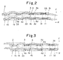
- the chain guide portion 4 recessed as above-mentioned, is preferable to be deep enough to engage a space 3a between the outer link plates 31 with the first tooth 11 when the outer link plates 31 corresponds to the first tooth 11 as shown in Fig.2 and to prevent the inner link plate 32 at the chain 3 from riding on the first tooth 11 when the inner link plate 32 corresponds to the first tooth 11 as shown in Fig.3.
- the chain 3 is preferred to be controlled of its movement with respect to the larger diameter sprocket 1.
- the chain guide portion 4 may alternatively be formed of a cutout, but when it is recessed, the movement of the chain 3 can be controlled and a stepped portion 4a can receive the link plate of the chain 3 when shifted.
- a distance L between the centers 01 and 02 is equal to two pitch of chain 3 as shown by the chain line in Fig.1.
- the chain guide portion 4 at the inside surface 1a of larger diameter sprocket 1 is formed in the size from an initial end edge 4b to a termination 4d at the sprocket 1, the initial end edge 4b being somewhat apart from the position corresponding to the center 02 between the two adjacent teeth at the sprocket 2 toward the center 02 between two adjacent teeth at the sprocket 1, the termination 4d being the tooth bottom between the first tooth 11 and a tooth 10 positioned ahead of the center 02 in the driving rotation direction ( the direction of the arrow X ) of the sprocket 1.
- the inner link plate 32 positioned ahead of the outer link plate 31 in the traveling direction ( in the direction of the arrow Y in Fig.1) of the chain3, part of an outer link plate 31 positioned ahead of the inner link plate 32 in the traveling direction , and a link pin 33 for connecting the link plates 32 and 31, the link pin 33 abutting at its end face against the bottom 4c of recessed chain guide portion 4.
- a depth D1 (in Fig.6) in a range from an intermediate portion between the initial end 4b and the termination 4d to the termination 4d is made larger than that D2 (in Fig.5) in a range from the initial end edge 4b to the intermediate portion.
- a stepped portion 4e is provided at the intermediate portion of the guide portion 4 so as to stepwise change the depth thereof, but the chain guide portion 4 may alternatively be inclined throughout the entire length.
- teeth facing the chain guide portion 4 each are reduced in thickness to an extent corresponding to the depth of the guide portion 4, it is preferable to make these teeth larger in circumferential width than other teeth as shown in Figs.1 and 4, thereby restricting lowering of strength.
- All the teeth except for the first and second teeth 11 and 12 are made not-easy-engageable.
- the not-easy-engageable teeth as shown in Figs.2 and 3, each are chamfered at the inner surface facing the smaller diameter sprocket 2, or, as shown in Fig.7, inclined forwardly in the driving rotation direction ( in the direction of the arrow X ) and reversely to the smaller diameter sprocket 2, that is, toward the outside surface of the larger diameter sprocket 1 with respect to the center line of thickness between the inside surface 1a and the outside surface 1b of the larger diameter sprocket 1, thereby being made difficult to engage with the chain 3.
- first and second teeth 11 and 12 are not made not-easy-engageable because the chain 3 is intended to reliably engage with the first tooth 11,and the spaces 3a and 3b between the link plates of the chain 3 in engagement with the tooth 11 are intended to reliably engage with the second tooth 12, whereby the first and second teeth 11 and 12 are preferred to be easily engageable with the chain 3.
- a length between the adjacent teeth and on the pitch circle of the respective sprockets 1 and 2 is made larger by a predetermined length than an outer diameter of a roller at the chain 3. Accordingly, the distance L between the centers 01 and 02 is smaller than an integer multiple of chain pitch.
- the chain guide portion 4 is provided on the traveling path of the chain 3 when traveling between the centers 01 and 02 , so that the chain 3 travels at a predetermined amount toward the outside surface of the sprocket 1, thereby reliably engaging with the first tooth 11 thereof.
- the chain guide portion 4 is recessed to an extent that the inner link plate 32 of chain 3 at the larger diameter sprocket 1 side does not ride on the first tooth 11, when the inner link plate 32 is positioned corresponding thereto, the outer link plate 31 abuts against the termination 4d of chain gudie portion 4 as shown in Fig.3 and the chain 3 is restricted from moving toward the outside surface, thereby preventing the inner link plate 32 from riding on the first tooth 11.
- the chain 3 can inevitably engage with the first or second tooth 11 or 12 because all other teeth are not-easy-engageable , thereby smoothly shifting the chain 3.
- a third tooth 13 positioned behind the second tooth 12 in the driving rotation direction of the sprocket 1 may not be a not-easy-engageable tooth but be a speed change tooth engageble with the chain 3.
- first tooth 11 is provided with a chain guide surface 11a for guiding therethrough the chain 3 reversely to the sprocket 2, the second tooth 12 is displaced reversely thereto with respect to the first tooth 11, and the third tooth 13 with respect to the second tooth 12 , so that the second tooth 12 is easily engageable with the chain 3 subsequently to the first tooth 11, the third tooth 13 being not difficult but not-easier to engage with the chain 3 than the second tooth 12.
- the chain guide surface 11a is inclined rearwardly in the driving rotation direction of the larger diameter sprocket 1 and reversely to the smaller diameter sprocket 2 with respect to the center line of thickness of the sprocket 1.
- the chain guide surface 11a may be formed in such a manner that the first tooth 11 is parallel to the aforesaid center line and cutout at a portion rearward in the driving rotation direction of the sprocket 1 and facing the smaller diameter sprocket 2, for example, at a portion from the bottom to the crest of the tooth.
- the space 3a between the outer line plates 31 firstly engages with the first tooth 11, whereby the first tooth 11 is made most easily engageable with the chain 3.
- the second tooth 12 is made easy to engage with the chain 3, whereby a narrow space 3b between the inner link plates 32 behind the wide space 3a is easily engageable with the second tooth 12, and , when the inner link plates are biased at the position corresponding to the first tooth 11 and the first tooth 11 cannot catch the space 3a , the second tooth 12 is adapted to catch the space 3a .
- the narrow space 3b adjacent thereto is adapted to be easy to engage with the third tooth 13 made easily engageable with the chain 3.
- the reason for reducing displacement of the third tooth 13 toward the smaller diameter sprocket 2 more than that of the second tooth 12 is that,when the inner link plates are biased at the position corresponding to the second tooth 12 so that the first and second teeth 11 and 12 cannot catch the wide space 3a , the outer link plate is prevented from riding on the third tooth 13.
- the third tooth 13 is easily engageable with the chain 3 and the first tooth 11 is provided with the chain guide surface 11a , so that the chain 3, when shifted from the sprocket 2 to that 1, can be displaced reversely to the sprocket 2 more than when the guide surface 11a is not provided, and correspondingly the second tooth 12 is displaced reversely to the sprocket 2 and the third tooth 13 with respect to the second tooth 12, thereby reliably preventing the outer link plate 31 from riding on the third tooth 13. Also, the chain 3 can smoothly engage with the third tooth 13 without riding thereon and eliminate sounds generated when engaging with the chain 3.
- the space 3b between the inner link plates 32 does not engage with the first tooth 11, but a space 3a between the next outer link plates 31 positioned behind the inner link plates 32 in the traveling direction (the direction of the arrow Y ) engages with the second tooth 12.
- the next inner link plates 32 positioned behind the outer link plates 31 in the traveling direction correspond to the third tooth 13. Since the third tooth 13 is the speed change tooth, the space 3b between the inner link plates 32 engages with the third tooth 13, whereby the chain 3 is quickly shifted to the larger diameter sprocket 1.
- the multistage sprocket assembly may comprise three sprockets or more and may be used for a crank means at the bicycle.
- the present invention assembles at least one larger diameter sprocket 1 and at least one smaller diameter sprocket 2 in the relation that the center 02 between a pair of adjacent teeth at the sprocket 1 is positioned on the tangent extending from the center 01 between a pair of adjacent teeth at the sprocket 2, makes the distance between the ceters 01 and 02 substantially an integer multiple of chain pitch, and provides the chain guide portion 4 allowing the chain 3 to deviate axially outwardly of the sprocket 1 at the inside surface thereof facing the sprocket 2 and corrsponding to the traveling path of the chain 3 when traveling between the centers 01 and 02 , whereby, when the chain 3 is shifted from the smaller diameter sprocket 2 to the larger diameter one 1, the chain can smoothly engage with the sprocket 1 and the chain guide portion 4 can displace by the predetermined amount axially outwardly of the sprocket 1.
- the space between the outer link plates 31 can reliably engage with the first tooth behind the center 02 , and also the inner link plates 32, even when corresponding to the first tooth 11 but not engaging therewith, never rides on the first tooth 11, thereby reliably engaging the outer link plates 31 behind the inner link plate 32 in the traveling direction.
- the inner link plates 32 behind the outer link plates 31 in the traveling direction can reliably engage with the third tooth 13 positioned behind the second tooth 12 in the driving rotation direction of the sprocket 1.
Landscapes
- Engineering & Computer Science (AREA)
- Chemical & Material Sciences (AREA)
- Combustion & Propulsion (AREA)
- Transportation (AREA)
- Mechanical Engineering (AREA)
- Gears, Cams (AREA)
- Devices For Conveying Motion By Means Of Endless Flexible Members (AREA)
- Transmissions By Endless Flexible Members (AREA)
Applications Claiming Priority (4)
| Application Number | Priority Date | Filing Date | Title |
|---|---|---|---|
| JP1987161539U JPH0711024Y2 (ja) | 1987-10-21 | 1987-10-21 | 自転車用多段スプロケット装置 |
| JP161539/87 | 1987-10-21 | ||
| JP1988074583U JPH0721434Y2 (ja) | 1988-06-04 | 1988-06-04 | 自転車用多段スプロケット装置 |
| JP74583/88 | 1988-06-04 |
Publications (3)
| Publication Number | Publication Date |
|---|---|
| EP0313345A2 true EP0313345A2 (de) | 1989-04-26 |
| EP0313345A3 EP0313345A3 (en) | 1990-07-25 |
| EP0313345B1 EP0313345B1 (de) | 1994-01-12 |
Family
ID=26415739
Family Applications (1)
| Application Number | Title | Priority Date | Filing Date |
|---|---|---|---|
| EP88309839A Expired - Lifetime EP0313345B1 (de) | 1987-10-21 | 1988-10-20 | Zusammenbau eines mehrstufigen Kettenrades für ein Fahrrad |
Country Status (4)
| Country | Link |
|---|---|
| US (1) | US4889521B1 (de) |
| EP (1) | EP0313345B1 (de) |
| KR (1) | KR910007224Y1 (de) |
| DE (2) | DE3887076T2 (de) |
Cited By (21)
| Publication number | Priority date | Publication date | Assignee | Title |
|---|---|---|---|---|
| EP0396091A1 (de) * | 1989-05-01 | 1990-11-07 | Shimano Inc. | Mehrstufiges Kettenrad für Fahrrad |
| EP0444645A1 (de) * | 1990-02-28 | 1991-09-04 | Shimano Inc. | Zusammenbau eines mehrstufigen Kettenrades für ein Fahrrad |
| EP0444556A1 (de) * | 1990-02-28 | 1991-09-04 | Shimano Inc. | Zusammenbau eines mehrstufigen Kettenrades für ein Fahrrad |
| EP0444557A1 (de) * | 1990-02-28 | 1991-09-04 | Shimano Industrial Company Limited | Zusammenbau eines mehrstufigen Kettenrades für ein Fahrrad |
| EP0474139A1 (de) * | 1990-09-04 | 1992-03-11 | Shimano Inc. | Zusammenbau eines mehrstufigen Kettenrades für ein Fahrrad |
| EP0479032A1 (de) * | 1990-09-18 | 1992-04-08 | Maeda Industries, Ltd. | Zusammenbau eines mehrstufigen Kettenrades für ein Fahrrad |
| EP0505809A1 (de) * | 1991-03-29 | 1992-09-30 | Sakae Co., Ltd. | Zusammenbau eines mehrstufigen Kettenrades für ein Fahrrad |
| EP0538780A1 (de) * | 1991-10-21 | 1993-04-28 | Shimano Inc. | Tragelement für eine Fahrradkettenschaltung |
| EP0642972A1 (de) * | 1993-09-13 | 1995-03-15 | FICHTEL & SACHS AG | Kettenschaltung, insbesondere für Fahrräder |
| DE4434752A1 (de) * | 1994-09-29 | 1996-04-04 | Fichtel & Sachs Ag | Kettenschaltung, insbesondere für Fahrräder |
| US5738603A (en) * | 1994-12-16 | 1998-04-14 | Fichtel & Sachs Ag | Derailleur |
| CN1047562C (zh) * | 1994-07-14 | 1999-12-22 | 财团法人工业技术研究院 | 自行车多段链轮组齿盘的修整方法及其结构 |
| EP0934871A3 (de) * | 1998-02-04 | 2001-01-17 | Shimano Inc. | Kettenrad für Fahrrad |
| DE4418407C2 (de) * | 1993-06-03 | 2002-11-07 | Campagnolo Srl | Kettenritzelanordnung für Fahrräder |
| EP1426283A2 (de) * | 2002-12-05 | 2004-06-09 | HANS HELMIG GmbH | Kettenradsatz |
| EP1522490A2 (de) | 2003-10-10 | 2005-04-13 | SRAM Deutschland GmbH | Geräuscharmes Kettenrad |
| EP1679255A3 (de) * | 2005-01-08 | 2006-11-29 | Shimano Inc. | Zahn eines Fahrradzahnrads |
| EP1832503A2 (de) | 2006-03-07 | 2007-09-12 | SRAM Deutschland GmbH | Mehrfachkettenradeinheit und Kettenschaltung, insbesondere für Fahrräder |
| DE102015219522A1 (de) | 2014-10-14 | 2016-04-14 | Sram Deutschland Gmbh | Mehrfach-Kettenradanordnung für eine Hinterradnabe |
| DE202020000984U1 (de) | 2020-04-01 | 2020-04-15 | Sram Deutschland Gmbh | Schaltgassen an Mehrfachanordnungen von Kettenrädern |
| EP3187408B1 (de) * | 2015-12-23 | 2021-10-20 | SRAM Deutschland GmbH | Antriebsanordnung eines fahrrades mit einer mehrfach-kettenradanordnung |
Families Citing this family (52)
| Publication number | Priority date | Publication date | Assignee | Title |
|---|---|---|---|---|
| JPH03295U (de) * | 1989-02-15 | 1991-01-07 | ||
| JP3509214B2 (ja) * | 1994-09-09 | 2004-03-22 | 株式会社シマノ | 自転車用チェーンホイール |
| US5569107A (en) * | 1995-05-31 | 1996-10-29 | Falcon Industrial Co., Ltd. | Multi-step bicycle transmission sprocket assembly |
| US5514042A (en) * | 1995-08-01 | 1996-05-07 | Liou; Yan-Shing | Multistage sprocket mechanism for a bicycle |
| US5545096A (en) * | 1995-08-29 | 1996-08-13 | Su; Bor-Lin | Sprocket mechanism for a multistage bicycle |
| JP3562883B2 (ja) * | 1995-09-29 | 2004-09-08 | 株式会社シマノ | 自転車後輪用多段ホイール |
| US5876295A (en) * | 1996-01-23 | 1999-03-02 | Cloyes Gear And Products, Inc. | Roller chain drive system having improved noise characteristics |
| US5690568A (en) * | 1996-01-31 | 1997-11-25 | Borg-Warner Automotive, Inc. | Idler sprocket assembly for a phased chain system |
| DE19606667C2 (de) * | 1996-02-23 | 1999-10-14 | Sram De Gmbh | Kettenschaltung für Fahrräder |
| US5921878A (en) * | 1996-07-03 | 1999-07-13 | Cloyes Gear And Products, Inc. | Roller chain drive system having improved noise characteristics |
| WO1998004848A2 (en) * | 1996-07-25 | 1998-02-05 | Cloyes Gear And Products, Inc. | Random engagement roller chain sprocket having improved noise characteristics |
| US6090003A (en) * | 1996-07-25 | 2000-07-18 | Cloyes Gear & Products, Inc. | Random engagement roller chain sprocket having improved noise characteristics |
| US5921879A (en) | 1996-07-25 | 1999-07-13 | Cloyes Gear And Products, Inc. | Random engagement roller chain sprocket with staged meshing and flank relief to provide improved noise characteristics |
| US5954604A (en) * | 1996-11-21 | 1999-09-21 | Shimano, Inc. | Multiple sprocket assembly for a bicycle |
| US6761657B2 (en) | 1996-12-19 | 2004-07-13 | Cloyes Gear And Products, Inc. | Roller chain sprocket with added chordal pitch reduction |
| US7416500B2 (en) * | 1996-12-19 | 2008-08-26 | Cloyes Gear And Products, Inc. | Random engagement roller chain sprocket and timing chain system including same |
| US6045472A (en) * | 1997-12-30 | 2000-04-04 | National Science Council | Integrated up-and downshifting configuration of a multistage sprocket assembly for a bicycle |
| US6676549B1 (en) * | 1998-12-18 | 2004-01-13 | Shimano, Inc. | Motion sensor for use with a bicycle sprocket assembly |
| US6415532B1 (en) | 2000-07-31 | 2002-07-09 | The Toro Company | Drive sprocket for a roller chain for material removal implement |
| US6340338B1 (en) | 2000-09-13 | 2002-01-22 | Shimano Inc. | Bicycle sprocket |
| US6923741B2 (en) * | 2002-08-30 | 2005-08-02 | Shimano Inc. | Top sprocket for a rear sprocket assembly and rear sprocket assembly for a bicycle |
| US8096908B2 (en) * | 2004-12-14 | 2012-01-17 | Shimano, Inc. | Bicycle sprocket with a laterally projecting gear change tooth |
| US7942771B2 (en) * | 2005-12-13 | 2011-05-17 | Shimano, Inc. | Bicycle sprocket apparatus with a shift inhibiting structure |
| US7959529B2 (en) * | 2007-03-21 | 2011-06-14 | Sram, Llc | Bicycle multi-gear cassette |
| JP2009103185A (ja) * | 2007-10-22 | 2009-05-14 | Tsubakimoto Chain Co | チェーン伝動装置 |
| US8235850B2 (en) * | 2008-12-01 | 2012-08-07 | Tien Hsin Industries Co., Ltd. | Multiple sprocket assembly |
| DE102008060501B4 (de) * | 2008-12-04 | 2015-10-15 | Tien Hsin Industries Co., Ltd. | Mehrfachzahnkranzanordnung |
| US8820192B2 (en) | 2009-04-29 | 2014-09-02 | Race Face Prerformance Products Inc. | Bicycle crank arm and insert therefore |
| US8177670B2 (en) | 2009-09-01 | 2012-05-15 | Shimano Inc. | Bicycle sprocket |
| TWM372828U (en) | 2009-09-11 | 2010-01-21 | Sen-Biao Lai | Free wheel of bicycle |
| US9376165B2 (en) | 2009-10-16 | 2016-06-28 | Shimano Inc. | Bicycle sprocket |
| US8491428B2 (en) | 2010-01-26 | 2013-07-23 | Shimano Inc. | Bicycle structure |
| US8500581B2 (en) | 2010-12-02 | 2013-08-06 | Chang Hui Lin | Multiple sprocket assembly for bicycle |
| US9327792B2 (en) | 2011-01-28 | 2016-05-03 | Paha Designs, Llc | Gear transmission and derailleur system |
| US9033833B2 (en) | 2011-01-28 | 2015-05-19 | Paha Designs, Llc | Gear transmission and derailleur system |
| US10207772B2 (en) | 2011-01-28 | 2019-02-19 | Paha Designs, Llc | Gear transmission and derailleur system |
| US9297450B2 (en) * | 2014-04-02 | 2016-03-29 | Shimano Inc. | Bicycle rear sprocket |
| US9463844B2 (en) | 2014-09-01 | 2016-10-11 | Shimano Inc. | Bicycle sprocket and bicycle sprocket assembly |
| US9278728B1 (en) * | 2014-10-29 | 2016-03-08 | Shimano Inc. | Bicycle shifting control apparatus and method of controlling derailleur |
| CN112517887A (zh) | 2016-04-11 | 2021-03-19 | 福克斯制造有限公司 | 用于形成自行车前链轮组件的方法 |
| US9845861B1 (en) * | 2016-05-26 | 2017-12-19 | GM Global Technology Operations LLC | Rotatable assembly including a coupling interface |
| US9885409B1 (en) * | 2016-09-12 | 2018-02-06 | Shimano Inc. | Bicycle sprocket and bicycle rear sprocket assembly |
| US10507888B2 (en) * | 2016-11-10 | 2019-12-17 | Shimano Inc. | Bicycle crank assembly and bicycle sprocket assembly |
| CN108343708A (zh) * | 2017-01-23 | 2018-07-31 | 超汇桂盟传动(苏州)有限公司 | 链条及其内链片 |
| US10689067B2 (en) | 2017-03-03 | 2020-06-23 | Shimano Inc. | Bicycle sprocket assembly and bicycle drive train |
| US11014628B2 (en) | 2017-04-28 | 2021-05-25 | Fox Factory, Inc. | Cinch direct mount 2X ring system |
| DE102017121972A1 (de) | 2017-09-22 | 2019-03-28 | Schaeffler Technologies AG & Co. KG | Schaltsignalgeber sowie Schaltsystem und Verfahren zum Schalten einer ein Ritzelpaket mit Schaltgasse aufweisenden Kettenschaltung |
| US10800487B2 (en) * | 2018-05-24 | 2020-10-13 | Shimano Inc. | Bicycle sprocket and bicycle drive train |
| US10865870B2 (en) * | 2018-07-06 | 2020-12-15 | Shimano Inc. | Bicycle sprocket |
| US11359709B2 (en) | 2018-12-18 | 2022-06-14 | Fox Factory, Inc. | Chainring |
| US11680633B2 (en) | 2019-02-08 | 2023-06-20 | Fox Factory, Inc. | Chainring |
| US11591044B2 (en) | 2020-08-28 | 2023-02-28 | Shimano Inc. | Bicycle sprocket assembly and bicycle sprocket |
Citations (4)
| Publication number | Priority date | Publication date | Assignee | Title |
|---|---|---|---|---|
| GB2005363A (en) * | 1977-08-19 | 1979-04-19 | Shimano Industrial Co | Multi-speed sprocket and bicycle with such a sprocket |
| GB2005778A (en) * | 1977-08-17 | 1979-04-25 | Shimano Industrial Co | Sprocket and use thereof on bicycle |
| US4268259A (en) * | 1977-08-25 | 1981-05-19 | Shimano Industrial Company Limited | Multi-speed sprockets for a bicycle and the like |
| FR2469624A1 (fr) * | 1979-11-09 | 1981-05-22 | Thun Alfred & Co Gmbh | Changement de vitesse a chaine |
-
1988
- 1988-10-20 DE DE3887076T patent/DE3887076T2/de not_active Expired - Lifetime
- 1988-10-20 DE DE198888309839T patent/DE313345T1/de active Pending
- 1988-10-20 EP EP88309839A patent/EP0313345B1/de not_active Expired - Lifetime
- 1988-10-21 KR KR2019880017098U patent/KR910007224Y1/ko not_active IP Right Cessation
- 1988-10-24 US US07261323 patent/US4889521B1/en not_active Expired - Lifetime
Patent Citations (4)
| Publication number | Priority date | Publication date | Assignee | Title |
|---|---|---|---|---|
| GB2005778A (en) * | 1977-08-17 | 1979-04-25 | Shimano Industrial Co | Sprocket and use thereof on bicycle |
| GB2005363A (en) * | 1977-08-19 | 1979-04-19 | Shimano Industrial Co | Multi-speed sprocket and bicycle with such a sprocket |
| US4268259A (en) * | 1977-08-25 | 1981-05-19 | Shimano Industrial Company Limited | Multi-speed sprockets for a bicycle and the like |
| FR2469624A1 (fr) * | 1979-11-09 | 1981-05-22 | Thun Alfred & Co Gmbh | Changement de vitesse a chaine |
Cited By (42)
| Publication number | Priority date | Publication date | Assignee | Title |
|---|---|---|---|---|
| EP0396091A1 (de) * | 1989-05-01 | 1990-11-07 | Shimano Inc. | Mehrstufiges Kettenrad für Fahrrad |
| US5192249A (en) * | 1990-02-28 | 1993-03-09 | Shimano, Inc. | Multi-stage sprocket assembly for bicycle |
| EP0444645A1 (de) * | 1990-02-28 | 1991-09-04 | Shimano Inc. | Zusammenbau eines mehrstufigen Kettenrades für ein Fahrrad |
| EP0444556A1 (de) * | 1990-02-28 | 1991-09-04 | Shimano Inc. | Zusammenbau eines mehrstufigen Kettenrades für ein Fahrrad |
| EP0444557A1 (de) * | 1990-02-28 | 1991-09-04 | Shimano Industrial Company Limited | Zusammenbau eines mehrstufigen Kettenrades für ein Fahrrad |
| US5085621A (en) * | 1990-02-28 | 1992-02-04 | Shimano Corporation | Multi-stage sprocket assembly for bicycle |
| US5087226A (en) * | 1990-02-28 | 1992-02-11 | Shimano Corporation | Multi-stage sprocket assembly for bicycle |
| US5192248A (en) * | 1990-06-24 | 1993-03-09 | Shimano, Inc. | Multi-stage sprocket assembly for bicycle |
| EP0474139A1 (de) * | 1990-09-04 | 1992-03-11 | Shimano Inc. | Zusammenbau eines mehrstufigen Kettenrades für ein Fahrrad |
| EP0479032A1 (de) * | 1990-09-18 | 1992-04-08 | Maeda Industries, Ltd. | Zusammenbau eines mehrstufigen Kettenrades für ein Fahrrad |
| US5162022A (en) * | 1990-09-18 | 1992-11-10 | Maeda Industries, Ltd. | Multiple sprocket assembly for bicycle |
| US5188569A (en) * | 1991-03-29 | 1993-02-23 | Maeda Industries, Ltd. | Multiple sprocket assembly for bicycle |
| EP0505809A1 (de) * | 1991-03-29 | 1992-09-30 | Sakae Co., Ltd. | Zusammenbau eines mehrstufigen Kettenrades für ein Fahrrad |
| EP0538780A1 (de) * | 1991-10-21 | 1993-04-28 | Shimano Inc. | Tragelement für eine Fahrradkettenschaltung |
| US5413534A (en) * | 1991-10-21 | 1995-05-09 | Shimano Inc. | Chain shift aiding structure for bicycle sprocket |
| DE4418407C2 (de) * | 1993-06-03 | 2002-11-07 | Campagnolo Srl | Kettenritzelanordnung für Fahrräder |
| EP0642972A1 (de) * | 1993-09-13 | 1995-03-15 | FICHTEL & SACHS AG | Kettenschaltung, insbesondere für Fahrräder |
| DE4330989A1 (de) * | 1993-09-13 | 1995-03-16 | Fichtel & Sachs Ag | Kettenschaltung, insbesondere für Fahrräder |
| US5503598A (en) * | 1993-09-13 | 1996-04-02 | Fichtel & Sachs Ag | Derailleur arrangement, in particular for bicycles |
| CN1054818C (zh) * | 1993-09-13 | 2000-07-26 | Sram德国有限公司 | 用于自行车的链式换档变速器 |
| CN1047562C (zh) * | 1994-07-14 | 1999-12-22 | 财团法人工业技术研究院 | 自行车多段链轮组齿盘的修整方法及其结构 |
| DE4434752A1 (de) * | 1994-09-29 | 1996-04-04 | Fichtel & Sachs Ag | Kettenschaltung, insbesondere für Fahrräder |
| US5738603A (en) * | 1994-12-16 | 1998-04-14 | Fichtel & Sachs Ag | Derailleur |
| EP0934871A3 (de) * | 1998-02-04 | 2001-01-17 | Shimano Inc. | Kettenrad für Fahrrad |
| EP1426283A3 (de) * | 2002-12-05 | 2005-04-27 | HANS HELMIG GmbH | Kettenradsatz |
| EP1426283A2 (de) * | 2002-12-05 | 2004-06-09 | HANS HELMIG GmbH | Kettenradsatz |
| DE10347784B4 (de) * | 2003-10-10 | 2017-04-06 | Sram Deutschland Gmbh | Geräuscharme Kettenschaltung |
| US9528588B2 (en) | 2003-10-10 | 2016-12-27 | Sram Deutschland Gmbh | Low-noise sprocket |
| US10443685B2 (en) | 2003-10-10 | 2019-10-15 | Sram Deutschland, Gmbh | Low-noise chain |
| DE10347784A1 (de) * | 2003-10-10 | 2005-05-12 | Sram De Gmbh | Geräuscharme Kettenschaltung |
| US8517874B2 (en) | 2003-10-10 | 2013-08-27 | Sram Deutschland Gmbh | Low-noise chainwheel |
| EP1522490A2 (de) | 2003-10-10 | 2005-04-13 | SRAM Deutschland GmbH | Geräuscharmes Kettenrad |
| EP1679255A3 (de) * | 2005-01-08 | 2006-11-29 | Shimano Inc. | Zahn eines Fahrradzahnrads |
| US8226511B2 (en) | 2005-01-08 | 2012-07-24 | Shimano, Inc. | Bicycle sprocket tooth with a shift assist radius greater than a reference tooth radius |
| DE102006010498A1 (de) * | 2006-03-07 | 2007-09-13 | Sram Deutschland Gmbh | Mehrfachkettenradeinheit und Kettenschaltung, insbesondere für Fahrräder |
| EP1832503A2 (de) | 2006-03-07 | 2007-09-12 | SRAM Deutschland GmbH | Mehrfachkettenradeinheit und Kettenschaltung, insbesondere für Fahrräder |
| EP3009339A1 (de) | 2014-10-14 | 2016-04-20 | SRAM Deutschland GmbH | Mehrfach-kettenradanordnung für eine hinterradnabe |
| DE102015219522A1 (de) | 2014-10-14 | 2016-04-14 | Sram Deutschland Gmbh | Mehrfach-Kettenradanordnung für eine Hinterradnabe |
| EP3770054A1 (de) | 2014-10-14 | 2021-01-27 | SRAM Deutschland GmbH | Mehrfach-kettenradanordnung für eine hinterradnabe |
| EP3187408B1 (de) * | 2015-12-23 | 2021-10-20 | SRAM Deutschland GmbH | Antriebsanordnung eines fahrrades mit einer mehrfach-kettenradanordnung |
| DE202020000984U1 (de) | 2020-04-01 | 2020-04-15 | Sram Deutschland Gmbh | Schaltgassen an Mehrfachanordnungen von Kettenrädern |
| DE202020000984U8 (de) * | 2020-04-01 | 2021-04-22 | Sram Deutschland Gmbh | Schaltgassen an Mehrfachanordnungen von Kettenrädern |
Also Published As
| Publication number | Publication date |
|---|---|
| DE3887076D1 (de) | 1994-02-24 |
| DE3887076T2 (de) | 1994-07-21 |
| KR890008795U (ko) | 1989-05-29 |
| DE313345T1 (de) | 1990-05-03 |
| EP0313345A3 (en) | 1990-07-25 |
| US4889521B1 (en) | 1995-05-09 |
| EP0313345B1 (de) | 1994-01-12 |
| KR910007224Y1 (ko) | 1991-09-25 |
| US4889521A (en) | 1989-12-26 |
Similar Documents
| Publication | Publication Date | Title |
|---|---|---|
| EP0313345A2 (de) | Zusammenbau eines mehrstufigen Kettenrades für ein Fahrrad | |
| US5876296A (en) | Gear shifting sprocket set for bicycle chain wheel | |
| US5437582A (en) | Sprocket assembly for bicycles | |
| US10443685B2 (en) | Low-noise chain | |
| US5741196A (en) | Transmission chain particularly for a bicycle | |
| US5192248A (en) | Multi-stage sprocket assembly for bicycle | |
| JP2901268B2 (ja) | 多段ギヤ装置 | |
| EP0538780B1 (de) | Tragelement für eine Fahrradkettenschaltung | |
| US7491143B2 (en) | Sprocket of a chain transmission for a bicycle | |
| EP0479032B1 (de) | Zusammenbau eines mehrstufigen Kettenrades für ein Fahrrad | |
| EP1219533B1 (de) | Zusammenbau eines mehrstufigen Kettenrades mit Fase | |
| US5087226A (en) | Multi-stage sprocket assembly for bicycle | |
| US5073151A (en) | Multi-speed sprocket assembly for bicycle | |
| EP0444645A1 (de) | Zusammenbau eines mehrstufigen Kettenrades für ein Fahrrad | |
| US7846048B2 (en) | Multi-speed sprocket assembly | |
| US4102216A (en) | Driving chain for bicycles | |
| US5203745A (en) | Inner and outer chain plates for bicycle having multiple wheels | |
| US5921881A (en) | Narrow bicycle chain with inner links that receive sprocket teeth within a bottom recess | |
| US5569107A (en) | Multi-step bicycle transmission sprocket assembly | |
| EP0700823B1 (de) | Fahrradkettenrad | |
| US4955849A (en) | Front derailleur for use in bicycle | |
| US4596539A (en) | Bicycle drive chain | |
| CN212455361U (zh) | 链条及车轮传动装置 | |
| US5437577A (en) | Chain for a bicycle with derailleur | |
| JPH0711024Y2 (ja) | 自転車用多段スプロケット装置 |
Legal Events
| Date | Code | Title | Description |
|---|---|---|---|
| PUAI | Public reference made under article 153(3) epc to a published international application that has entered the european phase |
Free format text: ORIGINAL CODE: 0009012 |
|
| AK | Designated contracting states |
Kind code of ref document: A2 Designated state(s): DE FR GB IT SE |
|
| EL | Fr: translation of claims filed | ||
| DET | De: translation of patent claims | ||
| PUAL | Search report despatched |
Free format text: ORIGINAL CODE: 0009013 |
|
| AK | Designated contracting states |
Kind code of ref document: A3 Designated state(s): DE FR GB IT SE |
|
| 17P | Request for examination filed |
Effective date: 19900716 |
|
| 17Q | First examination report despatched |
Effective date: 19910819 |
|
| GRAA | (expected) grant |
Free format text: ORIGINAL CODE: 0009210 |
|
| AK | Designated contracting states |
Kind code of ref document: B1 Designated state(s): DE FR GB IT SE |
|
| ITF | It: translation for a ep patent filed | ||
| REF | Corresponds to: |
Ref document number: 3887076 Country of ref document: DE Date of ref document: 19940224 |
|
| ET | Fr: translation filed | ||
| PLBE | No opposition filed within time limit |
Free format text: ORIGINAL CODE: 0009261 |
|
| STAA | Information on the status of an ep patent application or granted ep patent |
Free format text: STATUS: NO OPPOSITION FILED WITHIN TIME LIMIT |
|
| 26N | No opposition filed | ||
| EAL | Se: european patent in force in sweden |
Ref document number: 88309839.4 |
|
| PGFP | Annual fee paid to national office [announced via postgrant information from national office to epo] |
Ref country code: GB Payment date: 19951011 Year of fee payment: 8 |
|
| PGFP | Annual fee paid to national office [announced via postgrant information from national office to epo] |
Ref country code: SE Payment date: 19951017 Year of fee payment: 8 |
|
| PG25 | Lapsed in a contracting state [announced via postgrant information from national office to epo] |
Ref country code: GB Effective date: 19961020 |
|
| PG25 | Lapsed in a contracting state [announced via postgrant information from national office to epo] |
Ref country code: SE Effective date: 19961021 |
|
| GBPC | Gb: european patent ceased through non-payment of renewal fee |
Effective date: 19961020 |
|
| EUG | Se: european patent has lapsed |
Ref document number: 88309839.4 |
|
| PGFP | Annual fee paid to national office [announced via postgrant information from national office to epo] |
Ref country code: DE Payment date: 20071018 Year of fee payment: 20 |
|
| PGFP | Annual fee paid to national office [announced via postgrant information from national office to epo] |
Ref country code: IT Payment date: 20071026 Year of fee payment: 20 |
|
| PGFP | Annual fee paid to national office [announced via postgrant information from national office to epo] |
Ref country code: FR Payment date: 20071009 Year of fee payment: 20 |