US10689067B2 - Bicycle sprocket assembly and bicycle drive train - Google Patents
Bicycle sprocket assembly and bicycle drive train Download PDFInfo
- Publication number
- US10689067B2 US10689067B2 US15/448,589 US201715448589A US10689067B2 US 10689067 B2 US10689067 B2 US 10689067B2 US 201715448589 A US201715448589 A US 201715448589A US 10689067 B2 US10689067 B2 US 10689067B2
- Authority
- US
- United States
- Prior art keywords
- sprocket
- tooth
- downshifting
- bicycle
- teeth
- Prior art date
- Legal status (The legal status is an assumption and is not a legal conclusion. Google has not performed a legal analysis and makes no representation as to the accuracy of the status listed.)
- Active, expires
Links
- 238000011144 upstream manufacturing Methods 0.000 claims description 24
- 101100096719 Arabidopsis thaliana SSL2 gene Proteins 0.000 description 48
- 101100366560 Panax ginseng SS10 gene Proteins 0.000 description 48
- 101100366711 Arabidopsis thaliana SSL13 gene Proteins 0.000 description 31
- 101100366561 Panax ginseng SS11 gene Proteins 0.000 description 31
- 101100366707 Arabidopsis thaliana SSL11 gene Proteins 0.000 description 29
- 101100366562 Panax ginseng SS12 gene Proteins 0.000 description 27
- 125000006850 spacer group Chemical group 0.000 description 12
- 239000013256 coordination polymer Substances 0.000 description 6
- 102220573536 C-C motif chemokine 5_T31A_mutation Human genes 0.000 description 3
- 230000004323 axial length Effects 0.000 description 3
- 102200049897 c.124A>G Human genes 0.000 description 3
- 102200044888 rs121913412 Human genes 0.000 description 3
- 102220035924 rs515726219 Human genes 0.000 description 3
- 101100365087 Arabidopsis thaliana SCRA gene Proteins 0.000 description 2
- 102220616482 Endoplasmic reticulum protein SC65_C12A_mutation Human genes 0.000 description 2
- 102220616478 Endoplasmic reticulum protein SC65_C21A_mutation Human genes 0.000 description 2
- 101001125214 Hordeum vulgare Non-specific lipid-transfer protein 4.1 Proteins 0.000 description 2
- 102220503937 Phosphoribosylformylglycinamidine synthase_C11A_mutation Human genes 0.000 description 2
- 230000000712 assembly Effects 0.000 description 2
- 238000000429 assembly Methods 0.000 description 2
- 102200061079 rs776498025 Human genes 0.000 description 2
- 230000002860 competitive effect Effects 0.000 description 1
- 238000010586 diagram Methods 0.000 description 1
- 230000009977 dual effect Effects 0.000 description 1
- 230000004048 modification Effects 0.000 description 1
- 238000012986 modification Methods 0.000 description 1
Images


Classifications
-
- B—PERFORMING OPERATIONS; TRANSPORTING
- B62—LAND VEHICLES FOR TRAVELLING OTHERWISE THAN ON RAILS
- B62M—RIDER PROPULSION OF WHEELED VEHICLES OR SLEDGES; POWERED PROPULSION OF SLEDGES OR SINGLE-TRACK CYCLES; TRANSMISSIONS SPECIALLY ADAPTED FOR SUCH VEHICLES
- B62M9/00—Transmissions characterised by use of an endless chain, belt, or the like
- B62M9/04—Transmissions characterised by use of an endless chain, belt, or the like of changeable ratio
- B62M9/06—Transmissions characterised by use of an endless chain, belt, or the like of changeable ratio using a single chain, belt, or the like
- B62M9/10—Transmissions characterised by use of an endless chain, belt, or the like of changeable ratio using a single chain, belt, or the like involving different-sized wheels, e.g. rear sprocket chain wheels selectively engaged by the chain, belt, or the like
- B62M9/105—Transmissions characterised by use of an endless chain, belt, or the like of changeable ratio using a single chain, belt, or the like involving different-sized wheels, e.g. rear sprocket chain wheels selectively engaged by the chain, belt, or the like involving front sprocket chain-wheels engaged by the chain, belt or the like
-
- B—PERFORMING OPERATIONS; TRANSPORTING
- B62—LAND VEHICLES FOR TRAVELLING OTHERWISE THAN ON RAILS
- B62M—RIDER PROPULSION OF WHEELED VEHICLES OR SLEDGES; POWERED PROPULSION OF SLEDGES OR SINGLE-TRACK CYCLES; TRANSMISSIONS SPECIALLY ADAPTED FOR SUCH VEHICLES
- B62M9/00—Transmissions characterised by use of an endless chain, belt, or the like
- B62M9/04—Transmissions characterised by use of an endless chain, belt, or the like of changeable ratio
- B62M9/06—Transmissions characterised by use of an endless chain, belt, or the like of changeable ratio using a single chain, belt, or the like
- B62M9/10—Transmissions characterised by use of an endless chain, belt, or the like of changeable ratio using a single chain, belt, or the like involving different-sized wheels, e.g. rear sprocket chain wheels selectively engaged by the chain, belt, or the like
- B62M9/12—Transmissions characterised by use of an endless chain, belt, or the like of changeable ratio using a single chain, belt, or the like involving different-sized wheels, e.g. rear sprocket chain wheels selectively engaged by the chain, belt, or the like the chain, belt, or the like being laterally shiftable, e.g. using a rear derailleur
-
- F—MECHANICAL ENGINEERING; LIGHTING; HEATING; WEAPONS; BLASTING
- F16—ENGINEERING ELEMENTS AND UNITS; GENERAL MEASURES FOR PRODUCING AND MAINTAINING EFFECTIVE FUNCTIONING OF MACHINES OR INSTALLATIONS; THERMAL INSULATION IN GENERAL
- F16H—GEARING
- F16H55/00—Elements with teeth or friction surfaces for conveying motion; Worms, pulleys or sheaves for gearing mechanisms
- F16H55/02—Toothed members; Worms
- F16H55/30—Chain-wheels
-
- B—PERFORMING OPERATIONS; TRANSPORTING
- B62—LAND VEHICLES FOR TRAVELLING OTHERWISE THAN ON RAILS
- B62M—RIDER PROPULSION OF WHEELED VEHICLES OR SLEDGES; POWERED PROPULSION OF SLEDGES OR SINGLE-TRACK CYCLES; TRANSMISSIONS SPECIALLY ADAPTED FOR SUCH VEHICLES
- B62M9/00—Transmissions characterised by use of an endless chain, belt, or the like
- B62M2009/005—Details of transmission chains specially adapted for bicycles
Definitions
- the present invention relates to a bicycle sprocket assembly and a bicycle drive train.
- Bicycling is becoming an increasingly more popular form of recreation as well as a means of transportation. Moreover, bicycling has become a very popular competitive sport for both amateurs and professionals. Whether the bicycle is used for recreation, transportation or competition, the bicycle industry is constantly improving the various components of the bicycle.
- One bicycle component that has been extensively redesigned is a sprocket.
- a bicycle sprocket assembly comprises a first sprocket and a second sprocket.
- the first sprocket includes a first sprocket body, first sprocket teeth, and a first pitch circle.
- the first sprocket teeth extend radially outwardly from an outer periphery of the first sprocket body.
- the first pitch circle has a first diameter.
- the second sprocket includes a second sprocket body, second sprocket teeth, and a second pitch circle.
- the second sprocket teeth extend radially outwardly from an outer periphery of the second sprocket body.
- the second pitch circle has a second diameter that is smaller than the first diameter.
- the second sprocket is adjacent to the first sprocket without another sprocket between the first sprocket and the second sprocket in an axial direction parallel to a rotational center axis of the bicycle sprocket assembly.
- the first sprocket teeth include a large-sprocket downshifting tooth to first receive a bicycle chain from the second sprocket in a first chain phase state in which the bicycle chain is shifted from the second sprocket to the first sprocket.
- the first sprocket teeth include an additional large-sprocket downshifting tooth to first receive the bicycle chain from the second sprocket in a second chain phase state in which the bicycle chain is shifted from the second sprocket to the first sprocket.
- the second chain phase state is different from the first chain phase state.
- the additional large-sprocket downshifting tooth is adjacent to the large-sprocket downshifting tooth without another tooth between the large-sprocket downshifting tooth and the additional large-sprocket downshifting tooth.
- the additional large-sprocket downshifting tooth is disposed on an upstream side of the large-sprocket downshifting tooth in a driving rotational direction in which the bicycle sprocket assembly is rotated about the rotational center axis during pedaling.
- the second sprocket teeth include a first small-sprocket downshifting tooth to facilitate a downshifting operation in which the bicycle chain is shifted from a third sprocket to the second sprocket.
- the third sprocket is adjacent to the second sprocket without another sprocket between the second sprocket and the third sprocket in the axial direction.
- the second sprocket teeth include a second small-sprocket downshifting tooth to facilitate a downshifting operation in which the bicycle chain is shifted from the third sprocket to the second sprocket.
- the second small-sprocket downshifting tooth is spaced apart from the first small-sprocket downshifting tooth in the circumferential direction.
- the second sprocket teeth include a first adjacent tooth adjacent to the first small-sprocket downshifting tooth without another tooth between the first small-sprocket downshifting tooth and the first adjacent tooth in the circumferential direction.
- the first adjacent tooth is disposed on an upstream side of the first small-sprocket downshifting tooth in the driving rotational direction.
- the second sprocket teeth include a second adjacent tooth adjacent to the second small-sprocket downshifting tooth without another tooth between the second small-sprocket downshifting tooth and the second adjacent tooth in the circumferential direction.
- the second adjacent tooth is disposed on a downstream side of the second small-sprocket downshifting tooth in the driving rotational direction.
- a circumferential area is defined from a driving surface of the first adjacent tooth to a non-driving surface of the second adjacent tooth in the driving rotational direction about the rotational center axis when viewed in the axial direction.
- the circumferential area has an angle equal to or smaller than 180 degrees about the rotational center axis.
- the large-sprocket downshifting tooth is disposed in the circumferential area when viewed in the axial direction.
- the bicycle sprocket assembly according to the first aspect is configured so that a total number of the second sprocket teeth is smaller than a total number of the first sprocket teeth by a tooth-number difference that is equal to or less than five.
- the bicycle sprocket assembly according to the second aspect is configured so that the tooth-number difference is equal to three.
- the bicycle sprocket assembly according to the second aspect is configured so that the tooth-number difference is equal to two.
- the bicycle sprocket assembly according to any one of the first to fourth aspects is configured so that a total number of the first sprocket teeth is equal to or less than 24.
- the bicycle sprocket assembly according to any one of the first to fifth aspects is configured so that the first sprocket teeth include at least one first tooth and at least one second tooth.
- the at least one first tooth has a first maximum axial width and a first center plane.
- the first maximum axial width is defined in an axial direction parallel to the rotational center axis.
- the first center plane is defined to bisect the first maximum axial width.
- the at least one second tooth has a second maximum axial and a second center plane.
- the second maximum axial width is defined in the axial direction.
- the second center plane is defined to bisect the second maximum axial width.
- the first center plane is offset from the second center plane in the axial direction.
- the bicycle sprocket assembly according to any one of the first to sixth aspects further comprising the third sprocket.
- the third sprocket comprises a third sprocket body and third sprocket teeth extending radially outwardly from an outer periphery of the third sprocket body.
- a total number of the third sprocket teeth is equal to or smaller than 10.
- the bicycle sprocket assembly according to any one of the first to seventh aspects further comprising a smallest sprocket having a minimum total number of sprocket teeth which is equal to or smaller than 10.
- the bicycle sprocket assembly according to any one of the first to eighth aspects further comprising a largest sprocket having a maximum total number of sprocket teeth which is equal to or larger than 46.
- the bicycle sprocket assembly according to the ninth aspect is configured so that the maximum total number of sprocket teeth is equal to or larger than 50.
- a bicycle sprocket assembly comprises a first sprocket and a second sprocket.
- the first sprocket includes a first sprocket body, first sprocket teeth, and a first pitch circle.
- the first sprocket teeth extend radially outwardly from an outer periphery of the first sprocket body. A total number of the first sprocket teeth is equal to or less than 24.
- the first pitch circle has a first diameter.
- the second sprocket includes a second sprocket body, second sprocket teeth, and a second pitch circle.
- the second sprocket teeth extend radially outwardly from an outer periphery of the second sprocket body.
- the second pitch circle has a second diameter that is smaller than the first diameter.
- the second sprocket is adjacent to the first sprocket without another sprocket between the first sprocket and the second sprocket in an axial direction parallel to a rotational center axis of the bicycle sprocket assembly.
- the first sprocket teeth include a large-sprocket downshifting tooth to first receive a bicycle chain from the second sprocket in a first chain phase state in which the bicycle chain is shifted from the second sprocket to the first sprocket.
- the second sprocket teeth include a first small-sprocket downshifting tooth to facilitate a downshifting operation in which the bicycle chain is shifted from a third sprocket to the second sprocket.
- the third sprocket is adjacent to the second sprocket without another sprocket between the second sprocket and the third sprocket in the axial direction.
- the second sprocket teeth include a second small-sprocket downshifting tooth to facilitate a downshifting operation in which the bicycle chain is shifted from the third sprocket to the second sprocket.
- the second small-sprocket downshifting tooth is spaced apart from the first small-sprocket downshifting tooth in the circumferential direction.
- the second sprocket teeth include a first adjacent tooth adjacent to the first small-sprocket downshifting tooth without another tooth between the first small-sprocket downshifting tooth and the first adjacent tooth in the circumferential direction.
- the first adjacent tooth is disposed on an upstream side of the first small-sprocket downshifting tooth in the driving rotational direction.
- the second sprocket teeth include a second adjacent tooth adjacent to the second small-sprocket downshifting tooth without another tooth between the second small-sprocket downshifting tooth and the second adjacent tooth in the circumferential direction.
- the second adjacent tooth is disposed on a downstream side of the second small-sprocket downshifting tooth in the driving rotational direction.
- a circumferential area is defined from a driving surface of the first adjacent tooth to a non-driving surface of the second adjacent tooth in the driving rotational direction when viewed in the axial direction.
- the circumferential area is equal to or smaller than 180 degrees.
- the large-sprocket downshifting tooth is disposed in the circumferential area when viewed in the axial direction.
- the bicycle sprocket assembly according to the eleventh aspect is configured so that the first sprocket teeth include at least one first tooth and at least one second tooth.
- the at least one first tooth has a first maximum axial width defined in an axial direction parallel to the rotational center axis.
- the at least one second tooth has a second maximum axial width defined in the axial direction.
- the first maximum axial width is larger than the second maximum axial width.
- a bicycle sprocket assembly comprises a first sprocket.
- the first sprocket includes a first sprocket body and first sprocket teeth.
- the first sprocket teeth extend radially outwardly from an outer periphery of the first sprocket body.
- a total number of the first sprocket teeth is equal to or larger than 14.
- the first sprocket teeth include a reference tooth and a downshifting tooth to facilitate a downshifting operation in which a bicycle chain is shifted from a second sprocket to the first sprocket.
- the second sprocket is adjacent to the first sprocket without another sprocket between the first sprocket and the second sprocket in an axial direction parallel to a rotational center axis of the bicycle sprocket assembly.
- the reference tooth has a reference circumferential width defined in a circumferential direction with respect to the rotational center axis.
- the downshifting tooth has a circumferential width defined in the circumferential direction.
- the reference circumferential width and the circumferential width are defined on a first pitch circle of the first sprocket.
- the circumferential width is larger than the reference circumferential width.
- the bicycle sprocket assembly according to the thirteenth aspect is configured so that the circumferential width is equal to or larger than 3.6 mm.
- the bicycle sprocket assembly according to the thirteenth or fourteenth aspect is configured so that the first sprocket teeth include an additional downshifting tooth to facilitate a downshifting operation in which a bicycle chain is shifted from a second sprocket to the first sprocket.
- the additional downshifting tooth is adjacent to the downshifting tooth without another tooth between the downshifting tooth and the additional downshifting tooth.
- the additional downshifting tooth is disposed on an upstream side of the downshifting tooth in a driving rotational direction in which the bicycle sprocket assembly is rotated about a rotational center axis during pedaling.
- a bicycle drive train comprises the bicycle sprocket assembly according to any one of the first to fifteenth aspects attached to a bicycle rear hub assembly, a bicycle front sprocket, and the bicycle chain.
- the bicycle chain is engaged with the bicycle front sprocket and the bicycle sprocket assembly to transmit a driving rotational force between the bicycle front sprocket and the bicycle sprocket assembly.
- the bicycle drive train according to the sixteenth aspect is configured so that the bicycle front sprocket comprised a solitary bicycle front sprocket.
- FIG. 1 is a schematic diagram of a bicycle drive train including a bicycle sprocket assembly in accordance with a first embodiment.
- FIG. 2 is a side elevational view of the bicycle sprocket assembly of the bicycle drive train illustrated in FIG. 1 .
- FIG. 3 is a front view of the bicycle sprocket assembly illustrated in FIG. 1 .
- FIG. 4 is a side elevational view of a first sprocket of the bicycle sprocket assembly illustrated in FIG. 1 (option OP 1 ).
- FIG. 5 is a side elevational view of a second sprocket of the bicycle sprocket assembly illustrated in FIG. 1 (option OP 1 ).
- FIG. 6 is a side elevational view of a third sprocket of the bicycle sprocket assembly illustrated in FIG. 1 (option OP 1 ).
- FIG. 7 is a side elevational view of the first to third sprockets of the bicycle sprocket assembly illustrated in FIG. 1 (option OP 1 ).
- FIG. 8 is a partial side elevational view of the first to third sprockets of the bicycle sprocket assembly illustrated in FIG. 1 , with a bicycle chain (first chain phase state) (option OP 1 ).
- FIG. 9 is another partial side elevational view of the first to third sprockets of the bicycle sprocket assembly illustrated in FIG. 1 , with a bicycle chain (second chain phase state) (option OP 1 ).
- FIG. 10 is a partial side elevational view of the first sprocket of the bicycle sprocket assembly illustrated in FIG. 1 (option OP 1 ).
- FIG. 11 is a cross-sectional view of the first sprocket taken along line XI-XI of FIG. 4 .
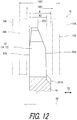
- FIG. 12 is a cross-sectional view of the first sprocket taken along line XII-XII of FIG. 4 .
- FIG. 13 is a table showing relationship between speed sprockets, a total number of teeth, and the first to third sprockets.
- FIG. 14 is a side elevational view of the first to third sprockets of the bicycle sprocket assembly illustrated in FIG. 1 (option OP 2 ).
- FIG. 15 is a partial side elevational view of the first sprocket of the bicycle sprocket assembly illustrated in FIG. 1 (option OP 2 ).
- FIG. 16 is a side elevational view of the first to third sprockets of the bicycle sprocket assembly illustrated in FIG. 1 (option OP 7 ).
- FIG. 17 is a partial side elevational view of the first sprocket of the bicycle sprocket assembly illustrated in FIG. 1 (option OP 7 ).
- FIG. 18 is a side elevational view of a bicycle sprocket assembly of a bicycle drive train in accordance with a second embodiment.
- FIG. 19 is a table showing relationship between speed sprockets, a total number of teeth, and the first to third sprockets.
- FIG. 20 is a side elevational view of the first to third sprockets of the bicycle sprocket assembly illustrated in FIG. 18 (option OP 1 ).
- FIG. 21 is a partial side elevational view of the first sprocket of the bicycle sprocket assembly illustrated in FIG. 18 (option OP 1 ).
- FIG. 22 is a side elevational view of a bicycle sprocket assembly of a bicycle drive train in accordance with a third embodiment.
- FIG. 23 is a partial side elevational view of a first sprocket of the bicycle sprocket assembly illustrated in FIG. 22 .
- FIG. 24 is a cross-sectional view of the first sprocket taken along line XXIV-XXIV of FIG. 23 .
- FIG. 25 is a cross-sectional view of the first sprocket taken along line XXV-XXV of FIG. 23 .
- FIG. 26 is a side elevational view of a bicycle sprocket assembly of a bicycle drive train in accordance with a fourth embodiment.
- FIG. 27 is a partial side elevational view of a first sprocket of the bicycle sprocket assembly illustrated in FIG. 26 .
- FIG. 28 is a cross-sectional view of the first sprocket taken along line XXVIII-XXVIII of FIG. 27 .
- FIG. 29 is a cross-sectional view of the first sprocket taken along line XXIX-XXIX of FIG. 27 .
- a bicycle drive train 10 in accordance with a first embodiment comprises a bicycle sprocket assembly 12 , a bicycle front sprocket 14 , and a bicycle chain 16 .
- the bicycle sprocket assembly 12 is attached to a bicycle rear hub assembly 18 .
- the bicycle rear hub assembly 18 is mounted to a bicycle frame BF.
- the bicycle sprocket assembly 12 has a rotational center axis A 1 and is rotatably supported by the bicycle rear hub assembly 18 relative to the bicycle frame BF about the rotational center axis Al.
- the bicycle chain 16 is engaged with the bicycle front sprocket 14 and the bicycle sprocket assembly 12 to transmit a driving rotational force F 1 between the bicycle front sprocket 14 and the bicycle sprocket assembly 12 .
- the bicycle front sprocket 14 comprised a solitary bicycle front sprocket.
- the bicycle sprocket assembly 12 is a bicycle rear sprocket assembly.
- the structure of the bicycle sprocket assembly 12 can be applied to a front sprocket assembly in a case where the front sprocket assembly includes at least two front sprockets.
- a total number of the bicycle front sprocket 14 is not limited to this embodiment.
- the following directional terms “front,” “rear,” “forward,” “rearward,” “left,” “right,” “transverse,” “upward” and “downward” as well as any other similar directional terms refer to those directions which are determined on the basis of a user (e.g., a rider) who sits on a saddle (not shown) of a bicycle with facing a handlebar (not shown). Accordingly, these terms, as utilized to describe the bicycle sprocket assembly 12 , should be interpreted relative to the bicycle equipped with the bicycle sprocket assembly 12 as used in an upright riding position on a horizontal surface.
- the bicycle sprocket assembly 12 is engaged with the bicycle chain 16 to transmit the driving rotational force F 1 between the bicycle sprocket assembly 12 and the bicycle front sprocket 14 ( FIG. 1 ).
- the bicycle sprocket assembly 12 is rotatable about the rotational center axis A 1 in a driving rotational direction D 11 during pedaling.
- a reverse rotational direction D 12 is opposite to the driving rotational direction D 11 .
- the driving rotational direction D 11 and the reverse rotational direction D 12 are defined along a circumferential direction D 1 of the bicycle sprocket assembly 12 .
- the circumferential direction D 1 is defined about the rotational center axis A 1 of the bicycle sprocket assembly 12 .
- the bicycle sprocket assembly 12 comprises first to twelfth speed sprockets SS 1 to SS 12 .
- Each of the first to twelfth speed sprockets SS 1 to SS 12 is engageable with the bicycle chain 16 .
- the first to twelfth speed sprockets SS 1 to SS 12 respectively have first to twelfth speed stages of the bicycle drive train 10 .
- the first speed sprocket SS 1 corresponds to the first speed stage (i.e., low gear) of the bicycle sprocket assembly 12 and has a largest pitch-circle diameter among the first to twelfth speed sprockets SS 1 to SS 12 .
- the twelfth speed sprocket SS 12 corresponds to the twelfth speed stage (i.e., top gear) of the bicycle sprocket assembly 12 and has a smallest pitch-circle diameter among the first to twelfth speed sprockets SS 1 to SS 12 .
- a total number of speed sprockets of the bicycle sprocket assembly 12 is not limited to this embodiment.
- the bicycle sprocket assembly 12 further comprises first to eleventh spacers SP 1 to SP 11 .
- the first spacer SP 1 is provided between the first speed sprocket SS 1 and the second speed sprocket SS 2 in the axial direction D 2 .
- the second spacer SP 2 is provided between the second speed sprocket SS 2 and the third speed sprocket SS 3 in the axial direction D 2 .
- the third spacer SP 3 is provided between the third speed sprocket SS 3 and the fourth speed sprocket SS 4 in the axial direction D 2 .
- the fourth spacer SP 4 is provided between the fourth speed sprocket SS 4 and the fifth speed sprocket SS 5 in the axial direction D 2 .
- the fifth spacer SP 5 is provided between the fifth speed sprocket SS 5 and the sixth speed sprocket SS 6 in the axial direction D 2 .
- the sixth spacer SP 6 is provided between the sixth speed sprocket SS 6 and the seventh speed sprocket SS 7 in the axial direction D 2 .
- the seventh spacer SP 7 is provided between the seventh speed sprocket SS 7 and the eighth speed sprocket SS 8 in the axial direction D 2 .
- the eighth spacer SP 8 is provided between the eighth speed sprocket SS 8 and the ninth speed sprocket SS 9 in the axial direction D 2 .
- the ninth spacer SP 9 is provided between the ninth speed sprocket SS 9 and the tenth speed sprocket SS 10 in the axial direction D 2 .
- the tenth spacer SP 10 is provided between the tenth speed sprocket SS 10 and the eleventh speed sprocket SS 11 in the axial direction D 2 .
- the eleventh spacer SP 11 is provided between the eleventh speed sprocket SS 11 and the twelfth speed sprocket SS 12 in the axial direction D 2 .
- an upshift occurs when the bicycle chain 16 is moved from a large sprocket to the next small sprocket by a derailleur DR in an upshifting direction D 31 .
- a downshift occurs when the bicycle chain 16 is moved from a small sprocket to the next large sprocket in a downshifting direction D 32 .
- the neighboring three speed sprockets can correspond to first to third sprockets.
- the tooth-number difference TND 1 can be equal to two or three in this embodiment.
- Options OP 1 to OP 6 correspond to the tooth-number difference TND 1 which is equal to two.
- Options OP 7 to OP 10 correspond to the tooth-number difference TND 1 which is equal to three.
- the tenth to twelfth speed sprockets SS 10 to SS 12 will be described in detail below regarding the option OP 1 .
- the tenth speed sprocket SS 10 , the eleventh speed sprocket SS 11 , and the twelfth speed sprocket SS 12 correspond to a first sprocket, a second sprocket, and a third sprocket, respectively.
- the bicycle sprocket assembly 12 comprises the first sprocket, the second sprocket, and the third sprocket.
- the eleventh speed sprocket SS 11 is adjacent to the tenth speed sprocket SS 10 without another sprocket between the tenth speed sprocket SS 10 and the eleventh speed sprocket SS 11 in the axial direction D 2 parallel to a rotational center axis A 1 of the bicycle sprocket assembly 12 .
- the twelfth speed sprocket SS 12 is adjacent to the eleventh speed sprocket SS 11 without another sprocket between the eleventh speed sprocket SS 11 and the twelfth speed sprocket SS 12 in the axial direction D 2 .
- the tenth speed sprocket SS 10 includes a tenth sprocket body 20 and a plurality of tenth sprocket teeth 22 .
- the tenth sprocket body 20 and the plurality of tenth sprocket teeth 22 correspond to a first sprocket body and a plurality of first sprocket teeth, respectively.
- the tenth sprocket teeth 22 extend radially outwardly from an outer periphery of the tenth sprocket body 20 .
- the tenth speed sprocket SS 10 includes a tenth pitch circle PC 10 having a tenth diameter DM 10 .
- the tenth pitch circle PC 10 and the tenth diameter DM 10 correspond to a first pitch circle and a first diameter, respectively.
- the tenth pitch circle PC 10 is defined by the tenth sprocket teeth 22 .
- the tenth pitch circle PC 10 is defined by centers of pins of the bicycle chain 16 engaged with the tenth speed sprocket SS 10 .
- the tenth speed sprocket SS 10 includes a tenth hub engagement part 23 provided on an inner periphery of the tenth sprocket body 20 to engage with the bicycle rear hub assembly 18 ( FIG. 3 ).
- a total number of the tenth sprocket teeth 22 is equal to or less than 24.
- the total number of the tenth sprocket teeth 22 is equal to or larger than 14. In this embodiment, the total number of the tenth sprocket teeth 22 is equal to 14. However, the total number of the tenth sprocket teeth 22 is not limited to this embodiment.
- the eleventh speed sprocket SS 11 includes an eleventh sprocket body 24 and a plurality of eleventh sprocket teeth 26 .
- the eleventh sprocket body 24 and the plurality of eleventh sprocket teeth 26 correspond to a second sprocket body and a plurality of second sprocket teeth, respectively.
- the eleventh sprocket teeth 26 extend radially outwardly from an outer periphery of the eleventh sprocket body 24 .
- the eleventh speed sprocket SS 11 includes an eleventh pitch circle PC 11 having an eleventh diameter DM 11 .
- the eleventh pitch circle PC 11 and the eleventh diameter DM 11 correspond to a second pitch circle and a second diameter, respectively.
- the eleventh pitch circle PC 11 is defined by the eleventh sprocket teeth 26 .
- the eleventh pitch circle PC 11 is defined by centers of pins of the bicycle chain 16 engaged with the eleventh speed sprocket SS 11 .
- the eleventh speed sprocket SS 11 includes a second hub engagement part 27 provided on an inner periphery of the eleventh sprocket body 24 to engage with the bicycle rear hub assembly 18 ( FIG. 3 ).
- a total number of the eleventh sprocket teeth 26 is 12.
- the total number of the eleventh sprocket teeth 26 is not limited to this embodiment.
- the twelfth speed sprocket SS 12 comprises a twelfth sprocket body 28 and a plurality of twelfth sprocket teeth 30 .
- the twelfth sprocket body 28 and the plurality of twelfth sprocket teeth 30 correspond to a third sprocket body and a plurality of third sprocket teeth, respectively.
- the twelfth sprocket teeth 30 extend radially outwardly from an outer periphery of the twelfth sprocket body 28 .
- the twelfth speed sprocket SS 12 includes a twelfth pitch circle PC 12 having a twelfth diameter DM 12 .
- the twelfth pitch circle PC 12 and the twelfth diameter DM 12 correspond to a third pitch circle and a third diameter.
- the twelfth pitch circle PC 12 is defined by the twelfth sprocket teeth 30 .
- the twelfth pitch circle PC 12 is defined by centers of pins of the bicycle chain 16 engaged with the twelfth speed sprocket SS 12 .
- the total number of the twelfth sprocket teeth 30 is equal to or smaller than 10.
- the total number of the twelfth sprocket teeth 30 is equal to 10.
- the total number of the twelfth sprocket teeth 30 is not limited to this embodiment.
- the total number of the eleventh sprocket teeth 26 is smaller than the total number of the tenth sprocket teeth 22 by a tooth-number difference TND 1 ( FIG. 13 ) that is equal to or less than five.
- the tooth-number difference TND 1 is equal to two since the total number of the tenth sprocket teeth 22 is 14 and the total number of the eleventh sprocket teeth 26 is 12.
- the tooth-number difference TND 1 is not limited to this embodiment.
- the total number of the twelfth sprocket teeth 30 is smaller than the total number of the tenth sprocket teeth 22 by the tooth-number difference TND 1 that is equal to or less than five.
- the tooth-number difference TND 1 is equal to two since the total number of the eleventh sprocket teeth 26 is 12 and the total number of the twelfth sprocket teeth 30 is 10.
- the tooth-number difference TND 1 is not limited to this embodiment.
- the bicycle sprocket assembly 12 comprises a smallest sprocket having a minimum total number of sprocket teeth which is equal to or smaller than 10.
- the twelfth speed sprocket SS 12 is the smallest sprocket.
- the eleventh diameter DM 11 is smaller than the tenth diameter DM 10 .
- the twelfth diameter DM 12 is smaller than the tenth diameter DM 10 and the eleventh diameter DM 11 .
- the tenth sprocket teeth 22 include a large-sprocket downshifting tooth 32 to first receive the bicycle chain 16 from the eleventh speed sprocket SS 11 in a first chain phase state ST 1 in which the bicycle chain 16 is shifted from the eleventh speed sprocket SS 11 to the tenth speed sprocket SS 10 .
- a large-sprocket downshifting tooth 32 to first receive the bicycle chain 16 from the eleventh speed sprocket SS 11 in a first chain phase state ST 1 in which the bicycle chain 16 is shifted from the eleventh speed sprocket SS 11 to the tenth speed sprocket SS 10 .
- the tenth sprocket teeth 22 include an additional large-sprocket downshifting tooth 34 to first receive the bicycle chain 16 from the eleventh speed sprocket SS 11 in a second chain phase state ST 2 in which the bicycle chain 16 is shifted from the eleventh speed sprocket SS 11 to the tenth speed sprocket SS 10 .
- the second chain phase state ST 2 is different from the first chain phase state ST 1 .
- each of the first chain phase state ST 1 and the second chain phase state ST 2 is defined a positional relationship between opposed pairs of outer link plates 16 A, opposed pairs of inner link plates 16 B, and the eleventh sprocket teeth 26 .
- the eleventh sprocket teeth 26 includes a chain-phase reference tooth 36 to define the first chain phase state ST 1 and the second chain phase state ST 2 .
- the chain-phase reference tooth 36 is provided in an outer link space 16 A 1 defined between the opposed pair of outer link plates 16 A in the first chain phase state ST 1 .
- the chain-phase reference tooth 36 is provided in an inner link space 16 B 1 defined between the opposed pair of inner link plates 16 B in the second chain phase state ST 2 .
- a circumferential positional relationship between the opposed pairs of outer link plates 16 A, the opposed pairs of inner link plates 16 B, and the eleventh sprocket teeth 26 in the second chain phase state ST 2 is different from a circumferential positional relationship between the opposed pairs of outer link plates 16 A, the opposed pairs of inner link plates 16 B, and the eleventh sprocket teeth 26 in the first chain phase state ST 1 .
- the large-sprocket downshifting tooth 32 can also be referred to as a downshifting tooth 32 .
- the additional large-sprocket downshifting tooth 34 can also be referred to as an additional downshifting tooth 34 .
- the tenth sprocket teeth 22 include the downshifting tooth 32 to facilitate a downshifting operation in which the bicycle chain 16 is shifted from the eleventh speed sprocket SS 11 to the tenth speed sprocket SS 10 .
- the tenth sprocket teeth 22 include the additional downshifting tooth 34 to facilitate a downshifting operation in which the bicycle chain 16 is shifted from the eleventh speed sprocket SS 11 to the tenth speed sprocket SS 10 .
- the additional large-sprocket downshifting tooth (the additional downshifting tooth) 34 is adjacent to the large-sprocket downshifting tooth (the downshifting tooth) 32 without another tooth between the large-sprocket downshifting tooth 32 and the additional large-sprocket downshifting tooth 34 .
- the additional large-sprocket downshifting tooth (the additional downshifting tooth) 34 is disposed on an upstream side of the large-sprocket downshifting tooth (the downshifting tooth) 32 in the driving rotational direction D 11 in which the bicycle sprocket assembly 12 is rotated about the rotational center axis A 1 during pedaling.
- the tenth speed sprocket SS 10 includes a downshifting facilitation recess 38 to facilitate a shifting operation in the first chain phase state and a shifting operation in the second chain phase state.
- the downshifting facilitation recess 38 reduces interference between the tenth speed sprocket SS 10 and the bicycle chain 16 in the first chain phase state and the second chain phase state.
- the downshifting facilitation recess 38 is adjacent to the large-sprocket downshifting tooth 32 without another tooth between the downshifting facilitation recess 38 and the large-sprocket downshifting tooth 32 in the driving rotational direction D 11 .
- the downshifting facilitation recess 38 is provided on a downstream side of the large-sprocket downshifting tooth 32 in the driving rotational direction D 11 .
- the tenth sprocket teeth 22 include a downshifting facilitation tooth 40 provided in the downshifting facilitation recess 38 .
- the downshifting facilitation tooth 40 is adjacent to the large-sprocket downshifting tooth 32 without another tooth between the downshifting facilitation tooth 40 and the large-sprocket downshifting tooth 32 in the driving rotational direction D 11 .
- the downshifting facilitation tooth 40 is provided on a downstream side of the large-sprocket downshifting tooth 32 in the driving rotational direction D 11 .
- the tenth sprocket teeth 22 include a plurality of large-sprocket downshifting teeth 32 , a plurality of additional large-sprocket downshifting teeth 34 , and a plurality of downshifting facilitation teeth 40 .
- the tenth speed sprocket SS 10 includes a plurality of downshifting facilitation recesses 38 .
- the tenth sprocket teeth 22 can include only one large-sprocket downshifting tooth 32 or at least three large-sprocket downshifting teeth 32 .
- the tenth sprocket teeth 22 can include only one additional large-sprocket downshifting tooth 34 or at least three additional large-sprocket downshifting teeth 34 .
- the tenth sprocket teeth 22 can include only one downshifting facilitation tooth 40 or at least three downshifting facilitation teeth 40 .
- the tenth speed sprocket SS 10 can include only one downshifting facilitation recess 38 or at least three downshifting facilitation recesses 38 .
- the tenth sprocket teeth 22 include a reference tooth 42 .
- the reference tooth 42 is adjacent to the additional large-sprocket downshifting tooth 34 without another tooth between the reference tooth 42 and the additional large-sprocket downshifting tooth 34 in the circumferential direction D 1 .
- the reference tooth 42 is provided on an upstream side of the additional large-sprocket downshifting tooth 34 in the driving rotational direction D 11 .
- the tenth sprocket teeth 22 include a plurality of reference teeth 42 . However, a total number of the reference tooth 42 is not limited to this embodiment.
- the reference tooth 42 has a reference circumferential width CW 1 defined in the circumferential direction D 1 with respect to the rotational center axis A 1 .
- the downshifting tooth 32 has a circumferential width CW 2 defined in the circumferential direction D 1 .
- the reference circumferential width CW 1 and the circumferential width CW 2 are defined on the tenth pitch circle PC 10 of the tenth speed sprocket SS 10 .
- the reference tooth 42 includes a driving surface 42 A and a non-driving surface 42 B.
- the driving surface 42 A is configured to be in contact with a roller 16 C ( FIG. 8 ) of the bicycle chain 16 to transmit the driving rotational force F 1 between the bicycle chain 16 and the tenth speed sprocket SS 10 during pedaling.
- the non-driving surface 42 B is provided on a reverse side of the driving surface 42 A in the circumferential direction D 1 .
- the non-driving surface 42 B is disposed on a downstream side of the driving surface 42 A in the driving rotational direction D 11 .
- the reference tooth 42 includes an upstream tooth bottom 42 C and a downstream tooth bottom 42 D.
- An upstream inscribed circle C 11 is defined by the driving surface 42 A and the upstream tooth bottom 42 C.
- a downstream inscribed circle C 12 is defined by the non-driving surface 42 B and the downstream tooth bottom 42 D.
- a center C 11 A of the upstream inscribed circle C 11 is defined on the tenth pitch circle PC 10 of the tenth speed sprocket SS 10 .
- a center C 12 A of the downstream inscribed circle C 12 is defined on the tenth pitch circle PC 10 of the tenth speed sprocket SS 10 .
- the reference circumferential width CW 1 is defined between the center C 11 A of the upstream inscribed circle C 11 and the center C 12 A of the downstream inscribed circle C 12 .
- the downshifting tooth 32 includes a driving surface 32 A and a non-driving surface 32 B.
- the driving surface 32 A is configured to be in contact with the roller 16 C ( FIG. 8 ) of the bicycle chain 16 to transmit the driving rotational force F 1 between the bicycle chain 16 and the tenth speed sprocket SS 10 during pedaling.
- the non-driving surface 32 B is provided on a reverse side of the driving surface 32 A in the circumferential direction D 1 .
- the non-driving surface 32 B is disposed on a downstream side of the driving surface 32 A in the driving rotational direction D 11 .
- the downshifting tooth 32 includes an upstream tooth bottom 32 C and a downstream tooth bottom 32 D.
- An upstream inscribed circle C 21 is defined by the driving surface 32 A and the upstream tooth bottom 32 C.
- a downstream inscribed circle C 22 is defined by the non-driving surface 32 B and the downstream tooth bottom 32 D.
- a center C 21 A of the upstream inscribed circle C 21 is defined on the tenth pitch circle PC 10 of the tenth speed sprocket SS 10 .
- a center C 22 A of the downstream inscribed circle C 22 is defined on the tenth pitch circle PC 10 of the tenth speed sprocket SS 10 .
- the circumferential width CW 2 is defined between the center C 21 A of the upstream inscribed circle C 21 and the center C 22 A of the downstream inscribed circle C 22 .
- the circumferential width CW 2 is larger than the reference circumferential width CW 1 .
- the circumferential width CW 2 is equal to or larger than 3.6 mm.
- the circumferential width CW 2 is equal to or smaller than 3.8 mm.
- the circumferential width CW 2 is equal to 3.68 mm
- the reference circumferential width CW 1 is equal to 3.42 mm.
- the reference circumferential width CW 1 and the circumferential width CW 2 are not limited to this embodiment. For example, if the total number of the tenth sprocket teeth 22 gets larger from 15, the reference circumferential width CW 1 gets smaller while the circumferential width CW 2 is substantially constant in each sprocket.
- the eleventh sprocket teeth 26 include a first small-sprocket downshifting tooth 44 to facilitate a downshifting operation in which the bicycle chain 16 is shifted from the twelfth speed sprocket SS 12 to the eleventh speed sprocket SS 11 .
- the eleventh sprocket teeth 26 include a second small-sprocket downshifting tooth 46 to facilitate a downshifting operation in which the bicycle chain 16 is shifted from the twelfth speed sprocket SS 12 to the eleventh speed sprocket SS 11 .
- the second small-sprocket downshifting tooth 46 is spaced apart from the first small-sprocket downshifting tooth 44 in the circumferential direction D 1 .
- each of the first small-sprocket downshifting tooth 44 and the second small-sprocket downshifting tooth 46 is configured to first receive the bicycle chain 16 from the twelfth speed sprocket SS 12 in the downshifting operation in which the bicycle chain 16 is shifted from the twelfth speed sprocket SS 12 to the eleventh speed sprocket SS 11 .
- the first small-sprocket downshifting tooth 44 and the second small-sprocket downshifting tooth 46 have substantially the same structures as that of the large-sprocket downshifting teeth 32 of the tenth speed sprocket SS 10 .
- the second small-sprocket downshifting tooth 46 has the same structure as that of the first small-sprocket downshifting tooth 44 .
- the second small-sprocket downshifting tooth 46 is disposed on an opposite side of the second small-sprocket downshifting tooth 46 with respect to the rotational center axis A 1 .
- the eleventh sprocket teeth 26 include a first adjacent tooth 48 adjacent to the first small-sprocket downshifting tooth 44 without another tooth between the first small-sprocket downshifting tooth 44 and the first adjacent tooth 48 in the circumferential direction D 1 .
- the first adjacent tooth 48 is disposed on an upstream side of the first small-sprocket downshifting tooth 44 in the driving rotational direction D 11 .
- the first adjacent tooth 48 is configured to first receive the bicycle chain 16 from the twelfth speed sprocket SS 12 in the downshifting operation in which the bicycle chain 16 is shifted from the twelfth speed sprocket SS 12 to the eleventh speed sprocket SS 11 .
- the first adjacent tooth 48 have substantially the same structures as that of the additional large-sprocket downshifting teeth 34 of the tenth speed sprocket SS 10 .
- the first adjacent tooth 48 includes a driving surface 48 A and a non-driving surface 48 B.
- the driving surface 48 A is configured to be in contact with the roller 16 C ( FIG. 8 ) of the bicycle chain 16 to transmit the driving rotational force F 1 between the bicycle chain 16 and the eleventh speed sprocket SS 11 during pedaling.
- the non-driving surface 48 B is provided on a reverse side of the driving surface 48 A in the circumferential direction D 1 .
- the non-driving surface 48 B is disposed on a downstream side of the driving surface 48 A in the driving rotational direction D 11 .
- the eleventh sprocket teeth 26 include a second adjacent tooth 50 adjacent to the second small-sprocket downshifting tooth 46 without another tooth between the second small-sprocket downshifting tooth 46 and the second adjacent tooth 50 in the circumferential direction D 1 .
- the second adjacent tooth 50 is disposed on a downstream side of the second small-sprocket downshifting tooth 46 in the driving rotational direction D 11 .
- the second adjacent tooth 50 includes a driving surface 50 A and a non-driving surface 50 B.
- the driving surface 50 A is configured to be in contact with the roller 16 C ( FIG. 8 ) of the bicycle chain 16 to transmit the driving rotational force F 1 between the bicycle chain 16 and the eleventh speed sprocket SS 11 during pedaling.
- the non-driving surface 50 B is provided on a reverse side of the driving surface 50 A in the circumferential direction D 1 .
- the non-driving surface 50 B is disposed on a downstream side of the driving surface 50 A in the driving rotational direction D 11 .
- a circumferential area CA 1 is defined from the driving surface 48 A of the first adjacent tooth 48 to the non-driving surface 50 B of the second adjacent tooth 50 in the driving rotational direction D 11 about the rotational center axis A 1 when viewed in the axial direction D 2 .
- the circumferential area CA 1 has an angle equal to or smaller than 180 degrees about the rotational center axis A 1 .
- the eleventh sprocket teeth 26 include a third adjacent tooth 52 adjacent to the first small-sprocket downshifting tooth 44 without another tooth between the first small-sprocket downshifting tooth 44 and the third adjacent tooth 52 in the circumferential direction D 1 .
- the third adjacent tooth 52 is disposed on a downstream side of the first small-sprocket downshifting tooth 44 in the driving rotational direction D 11 .
- the third adjacent tooth 52 includes a driving surface 52 A and a non-driving surface 52 B.
- the driving surface 52 A is configured to be in contact with the roller 16 C ( FIG. 8 ) of the bicycle chain 16 to transmit the driving rotational force F 1 between the bicycle chain 16 and the eleventh speed sprocket SS 11 during pedaling.
- the non-driving surface 52 B is provided on a reverse side of the driving surface 52 A in the circumferential direction D 1 .
- the non-driving surface 52 B is disposed on a downstream side of the driving surface 52 A in the driving rotational direction D 11 .
- the eleventh sprocket teeth 26 include a fourth adjacent tooth 54 adjacent to the second small-sprocket downshifting tooth 46 without another tooth between the second small-sprocket downshifting tooth 46 and the fourth adjacent tooth 54 in the circumferential direction D 1 .
- the fourth adjacent tooth 54 is disposed on an upstream side of the second small-sprocket downshifting tooth 46 in the driving rotational direction D 11 .
- the fourth adjacent tooth 54 is configured to first receive the bicycle chain 16 from the twelfth speed sprocket SS 12 in the downshifting operation in which the bicycle chain 16 is shifted from the twelfth speed sprocket SS 12 to the eleventh speed sprocket SS 11 .
- the fourth adjacent tooth 54 has substantially the same structures as that of the additional large-sprocket downshifting teeth 34 of the tenth speed sprocket SS 10 .
- the fourth adjacent tooth 54 includes a driving surface 54 A and a non-driving surface 54 B.
- the driving surface 54 A is configured to be in contact with the roller 16 C ( FIG. 8 ) of the bicycle chain 16 to transmit the driving rotational force F 1 between the bicycle chain 16 and the eleventh speed sprocket SS 11 during pedaling.
- the non-driving surface 54 B is provided on a reverse side of the driving surface 54 A in the circumferential direction D 1 .
- the non-driving surface 54 B is disposed on a downstream side of the driving surface 54 A in the driving rotational direction D 11 .
- An additional circumferential area CA 2 is defined from the non-driving surface 52 B of the third adjacent tooth 52 to the driving surface 54 A of the fourth adjacent tooth 54 in the driving rotational direction D 11 about the rotational center axis A 1 when viewed in the axial direction D 2 .
- the additional circumferential area CA 2 has an angle equal to or smaller than 180 degrees about the rotational center axis A 1 .
- the large-sprocket downshifting tooth 32 is disposed in the circumferential area CA 1 when viewed in the axial direction D 2 .
- One of the large-sprocket downshifting teeth 32 is disposed in the circumferential area CA 1 when viewed in the axial direction D 2 .
- the large-sprocket downshifting tooth 32 is entirely disposed in the circumferential area CA 1 when viewed in the axial direction D 2 .
- the large-sprocket downshifting tooth 32 can be partly disposed in the circumferential area CA 1 when viewed in the axial direction D 2 .
- the additional large-sprocket downshifting tooth 34 is disposed in the circumferential area CA 1 when viewed in the axial direction D 2 .
- One of the additional large-sprocket downshifting teeth 34 is disposed in the circumferential area CA 1 when viewed in the axial direction D 2 .
- the additional large-sprocket downshifting tooth 34 is partly disposed in the circumferential area CA 1 when viewed in the axial direction D 2 .
- the additional large-sprocket downshifting tooth 34 can be entirely disposed in the circumferential area CA 1 when viewed in the axial direction D 2 .
- At least one of the large-sprocket downshifting tooth 32 and the additional large-sprocket downshifting tooth 34 can be disposed outside the circumferential area CA 1 when viewed in the axial direction D 2 .
- the other of the large-sprocket downshifting teeth 32 is disposed in the additional circumferential area CA 2 when viewed in the axial direction D 2 .
- the other of the large-sprocket downshifting teeth 32 is entirely disposed in the additional circumferential area CA 2 when viewed in the axial direction D 2 .
- the large-sprocket downshifting tooth 32 can be partly disposed in the additional circumferential area CA 2 when viewed in the axial direction D 2 .
- the other of the additional large-sprocket downshifting teeth 34 is disposed in the additional circumferential area CA 2 when viewed in the axial direction D 2 .
- the other of the additional large-sprocket downshifting teeth 34 is partly disposed in the additional circumferential area CA 2 when viewed in the axial direction D 2 .
- the additional large-sprocket downshifting tooth 34 can be entirely disposed in the additional circumferential area CA 2 when viewed in the axial direction D 2 .
- At least one of the large-sprocket downshifting tooth 32 and the additional large-sprocket downshifting tooth 34 can be disposed outside the additional circumferential area CA 2 when viewed in the axial direction D 2 .
- the tenth sprocket teeth 22 include at least one first tooth T 1 and at least one second tooth T 2 .
- the tenth sprocket teeth 22 include first teeth T 1 and second teeth T 2 .
- the large-sprocket downshifting tooth 32 corresponds to the first tooth T 1 .
- the additional large-sprocket downshifting tooth 34 and the reference tooth 42 correspond to the second tooth T 2 .
- the large-sprocket downshifting tooth 32 and the additional large-sprocket downshifting tooth 34 will be described below as examples of the first tooth T 1 and the second tooth T 2 .
- the at least one first tooth T 1 has a first maximum axial width W 1 and a first center plane CP 1 .
- the first maximum axial width W 1 is defined in the axial direction D 2 parallel to the rotational center axis A 1 .
- the first center plane CP 1 is defined to bisect the first maximum axial width W 1 .
- the first tooth T 1 includes a first chain-engagement surface T 1 A and a first additional chain-engagement surface T 1 B provided on a reverse side of the first chain-engagement surface T 1 A in the axial direction D 2 .
- the first maximum axial width W 1 is defined between the first chain-engagement surface T 1 A and the first additional chain-engagement surface T 1 B in the axial direction D 2 .
- the at least one second tooth T 2 has a second maximum axial width W 2 and a second center plane CP 2 .
- the second maximum axial width W 2 is defined in the axial direction D 2 .
- the second center plane CP 2 is defined to bisect the second maximum axial width W 2 .
- the second tooth T 2 includes a second chain-engagement surface T 2 A and a second additional chain-engagement surface T 2 B provided on a reverse side of the second chain-engagement surface T 2 A in the axial direction D 2 .
- the second maximum axial width W 2 is defined between the second chain-engagement surface T 2 A and the second additional chain-engagement surface T 2 B in the axial direction D 2 .
- the first center plane CP 1 is offset from the second center plane CP 2 in the axial direction D 2 .
- the first maximum axial width W 1 is larger than the second maximum axial width W 2 .
- the first tooth T 1 is engageable with the inner link plates 16 B in the first chain phase state ST 1 ( FIG. 8 ) and engageable with the outer link plates 16 A in the second chain phase state ST 2 ( FIG. 9 ).
- the second tooth T 2 is engageable with the outer link plates 16 A in the first chain phase state ST 1 ( FIG. 8 ) and engageable with the inner link plates 16 B in the second chain phase state ST 2 ( FIG. 9 ).
- the bicycle chain 16 is shifted by the derailleur DR from the eleventh speed sprocket SS 11 toward the tenth speed sprocket SS 10 in each of the first chain phase state and the second chain phase state.
- the bicycle chain 16 is first received by the large-sprocket downshifting tooth 32 in the first chain phase state.
- the bicycle chain 16 is first received by the additional large-sprocket downshifting tooth 34 in the second chain phase state.
- the downshifting facilitation recess 38 allows the inner link plate 16 B of the bicycle chain 16 to come closer to the downshifting facilitation tooth 40 in the axial direction D 2 in a state where the bicycle chain 16 is shifted toward the tenth speed sprocket SS 10 in the first chain phase state ST 1 .
- This enables the large-sprocket downshifting tooth 32 to be smoothly inserted into the outer link space 16 A 1 of the opposed pair of outer link plates 16 A of the bicycle chain 16 .
- the bicycle chain 16 is first received by the large-sprocket downshifting tooth 32 in the first chain phase state.
- the additional large-sprocket downshifting tooth 34 is inserted into the inner link space 16 B 1 defined between the opposed pair of inner link plates 16 B after engagement of the large-sprocket downshifting tooth 32 .
- Other teeth of the tenth sprocket teeth 22 are alternately inserted into the outer link spaces 16 A 1 and the inner link spaces 16 B 1 of the bicycle chain 16 during rotation of the bicycle sprocket assembly 12 .
- the downshifting facilitation recess 38 allows the outer link plate of the bicycle chain 16 to come closer to the downshifting facilitation tooth 40 in the axial direction D 2 in a state where the bicycle chain 16 is shifted toward the tenth speed sprocket SS 10 in the second chain phase state ST 2 .
- This enables the additional large-sprocket downshifting tooth 34 to be smoothly inserted into the outer link space 16 A 1 of the opposed pair of outer link plates 16 A of the bicycle chain 16 .
- the bicycle chain 16 is first received by the additional large-sprocket downshifting tooth 34 in the second chain phase state.
- Other teeth of the tenth sprocket teeth 22 are alternately inserted into the inner link spaces 16 B 1 and the outer link spaces 16 A 1 of the bicycle chain 16 during rotation of the bicycle sprocket assembly 12 .
- the ninth to eleventh speed sprockets SS 9 to SS 11 can correspond to first to third sprockets. This corresponds to the option OP 2 of FIG. 13 .
- the ninth speed sprocket SS 9 has substantially the same structure as that of the tenth speed sprocket SS 10 .
- the tenth sprocket body 20 , the plurality of tenth sprocket teeth 22 , the tenth pitch circle PC 10 , and the tenth diameter DM 10 correspond to the second sprocket body, the plurality of second sprocket teeth, the second pitch circle, and the second diameter, respectively.
- the eleventh sprocket body 24 , the plurality of eleventh sprocket teeth 26 , the eleventh pitch circle PC 11 , and the eleventh diameter DM 11 correspond to the third sprocket body, the plurality of third sprocket teeth, the third pitch circle, and the third diameter, respectively.
- the ninth speed sprocket SS 9 comprises a ninth sprocket body 58 , a plurality of ninth sprocket teeth 60 , and a ninth pitch circle PC 9 having a ninth diameter DM 9 .
- the ninth sprocket body 58 , the plurality of ninth sprocket teeth 60 , the ninth pitch circle PC 9 , and the ninth diameter DM 9 correspond to the first sprocket body, the plurality of first sprocket teeth, the first pitch circle, and the first diameter, respectively.
- the ninth sprocket teeth 60 include large-sprocket downshifting teeth (downshifting teeth) 62 and additional large-sprocket downshifting teeth 64 .
- the ninth speed sprocket SS 9 includes downshifting facilitation recesses 68 .
- the ninth sprocket body 58 , the ninth sprocket teeth 60 , the ninth pitch circle PC 9 , the large-sprocket downshifting tooth (the downshifting tooth) 62 , the additional large-sprocket downshifting tooth 64 , and the downshifting facilitation recess 68 have substantially the same structures as those of the tenth sprocket body 20 , the tenth sprocket teeth 22 , the tenth pitch circle PC 10 , the large-sprocket downshifting tooth (the downshifting tooth) 32 , the additional large-sprocket downshifting tooth 34 , and the downshifting facilitation recess 38 of the tenth speed sprocket SS 10 ( FIGS. 4 and 7 ).
- the eleventh sprocket teeth 26 of the eleventh speed sprocket SS 11 includes the first small-sprocket downshifting tooth 32 (one of the large-sprocket downshifting teeth 32 , one of the downshifting teeth 32 ), the second small-sprocket downshifting tooth 32 (the other of the large-sprocket downshifting teeth 32 , the other of the downshifting teeth 32 ), the first adjacent tooth 34 (one of the additional large-sprocket downshifting teeth 34 ), and the second adjacent tooth (one of the downshifting facilitation teeth 40 ).
- a circumferential area CA 21 is defined from a driving surface 34 A of the first adjacent tooth 34 to a non-driving surface 40 B of the second adjacent tooth 40 in the driving rotational direction D 11 about the rotational center axis A 1 when viewed in the axial direction D 2 .
- the circumferential area CA 21 has an angle equal to or smaller than 180 degrees about the rotational center axis A 1 .
- the large-sprocket downshifting tooth 62 is disposed in the circumferential area CA 21 when viewed in the axial direction D 2 .
- the additional large-sprocket downshifting tooth 64 is disposed in the circumferential area CA 21 when viewed in the axial direction D 2 .
- the ninth sprocket teeth 60 include a reference tooth 66 .
- the reference tooth 66 has a reference circumferential width CW 21 defined in the circumferential direction D 1 with respect to the rotational center axis A 1 .
- the downshifting tooth 62 has a circumferential width CW 22 defined in the circumferential direction D 1 .
- the reference circumferential width CW 21 and the circumferential width CW 22 are defined on the ninth pitch circle PC 9 of the ninth speed sprocket SS 9 .
- the fourth to sixth speed sprockets SS 4 to SS 6 can correspond to first to third sprockets. This corresponds to the option OP 7 of FIG. 13 .
- the tooth-number difference TND 1 is equal to three.
- the fourth speed sprocket SS 4 comprises a fourth sprocket body 69 , a plurality of fourth sprocket teeth 70 , and a fourth pitch circle PC 4 having a fourth diameter DM 4 .
- the fourth sprocket body 69 , the plurality of fourth sprocket teeth 70 , the fourth pitch circle PC 4 , and the fourth diameter DM 4 correspond to the first sprocket body, the plurality of first sprocket teeth, the first pitch circle, and the first diameter, respectively.
- the fourth sprocket teeth 70 include large-sprocket downshifting teeth (downshifting teeth) 72 and additional large-sprocket downshifting teeth 74 .
- the fourth speed sprocket SS 4 includes downshifting facilitation recesses 78 .
- the fourth sprocket body 69 , the fourth sprocket teeth 70 , the fourth pitch circle PC 4 , the large-sprocket downshifting tooth (the downshifting tooth) 72 , the additional large-sprocket downshifting tooth 74 , and the downshifting facilitation recess 78 have substantially the same structures as those of the tenth sprocket body 20 , the tenth sprocket teeth 22 , the tenth pitch circle PC 10 , the large-sprocket downshifting tooth (the downshifting tooth) 32 , the additional large-sprocket downshifting tooth 34 , and the downshifting facilitation recess 38 of the tenth speed sprocket SS 10 ( FIGS. 4 and 7 ).
- the fifth speed sprocket SS 5 comprises a fifth sprocket body 79 , a plurality of fifth sprocket teeth 80 , and a fifth pitch circle PC 5 having a fifth diameter DM 5 .
- the fifth sprocket body 79 , the plurality of fifth sprocket teeth 80 , the fifth pitch circle PC 5 , and the fifth diameter DM 5 correspond to the second sprocket body, the plurality of second sprocket teeth, the second pitch circle, and the second diameter, respectively.
- the fifth sprocket teeth 80 of the fifth speed sprocket SS 5 includes a first small-sprocket downshifting tooth 82 , a second small-sprocket downshifting tooth 84 , a first adjacent tooth 86 , a second adjacent tooth 88 , a third adjacent tooth 90 , and a fourth adjacent tooth 92 .
- the first small-sprocket downshifting tooth 82 , the second small-sprocket downshifting tooth 84 , the first adjacent tooth 86 , the second adjacent tooth 88 , the third adjacent tooth 90 , and the fourth adjacent tooth 92 have substantially the same structures as those of the first small-sprocket downshifting tooth 44 , the second small-sprocket downshifting tooth 46 , the first adjacent tooth 48 , the second adjacent tooth 50 , the third adjacent tooth 52 , and the fourth adjacent tooth 54 of the eleventh speed sprocket SS 11 ( FIGS. 5 and 7 ).
- the sixth speed sprocket SS 6 comprises a sixth sprocket body 89 , a plurality of sixth sprocket teeth 90 , and a sixth pitch circle PC 6 having a sixth diameter DM 6 .
- the sixth sprocket body 89 , the plurality of sixth sprocket teeth 90 , the sixth pitch circle PC 6 , and the sixth diameter DM 6 correspond to the third sprocket body, the plurality of third sprocket teeth, the third pitch circle, and the third diameter, respectively.
- a circumferential area CA 31 is defined from a driving surface 86 A of the first adjacent tooth 86 to a non-driving surface 88 B of the second adjacent tooth 88 in the driving rotational direction D 11 about the rotational center axis A 1 when viewed in the axial direction D 2 .
- the circumferential area CA 31 has an angle equal to or smaller than 180 degrees about the rotational center axis A 1 .
- One of the large-sprocket downshifting teeth 72 is disposed in the circumferential area CA 31 when viewed in the axial direction D 2 .
- One of the additional large-sprocket downshifting teeth 74 is disposed in the circumferential area CA 31 when viewed in the axial direction D 2 .
- An additional circumferential area CA 32 is defined from a non-driving surface 90 B of the third adjacent tooth 90 to a driving surface 92 A of the fourth adjacent tooth 92 in the driving rotational direction D 11 about the rotational center axis A 1 when viewed in the axial direction D 2 .
- the additional circumferential area CA 32 has an angle equal to or smaller than 180 degrees about the rotational center axis A 1 .
- Another of the large-sprocket downshifting teeth 72 is disposed in the additional circumferential area CA 32 when viewed in the axial direction D 2 .
- Another of the additional large-sprocket downshifting teeth 74 is disposed in the additional circumferential area CA 32 when viewed in the axial direction D 2 .
- the fourth sprocket teeth 70 include a reference tooth 76 .
- the reference tooth 76 has a reference circumferential width CW 31 defined in the circumferential direction D 1 with respect to the rotational center axis A 1 .
- the downshifting tooth 72 has a circumferential width CW 32 defined in the circumferential direction D 1 .
- the reference circumferential width CW 31 and the circumferential width CW 32 are defined on the fourth pitch circle PC 4 of the fourth speed sprocket SS 4 .
- a bicycle drive train 210 comprising a bicycle sprocket assembly 212 in accordance with a second embodiment will be described below referring to FIGS. 18 to 21 .
- the bicycle drive train 210 has the same structure as that of the bicycle drive train 10 except for the bicycle sprocket assembly 212 .
- elements having substantially the same function as those in the first embodiment will be numbered the same here, and will not be described and/or illustrated again in detail here for the sake of brevity.
- the bicycle sprocket assembly 212 comprises first to twelfth speed sprockets SS 201 to SS 212 .
- the first to twelfth speed sprockets SS 201 to SS 212 have substantially the same structure as those of the first to twelfth speed sprockets SS 1 to SS 12 .
- a total number of sprocket teeth in each of the first to twelfth speed sprockets SS 201 to SS 212 is different from the total number of sprocket teeth in each of the first to twelfth speed sprockets SS 1 to SS 12 .
- FIG. 19 shows the total number of sprocket teeth in each of the first to twelfth speed sprockets SS 201 to SS 212 .
- the bicycle sprocket assembly 212 comprises a largest sprocket having a maximum total number of sprocket teeth which is equal to or larger than forty-six. In this embodiment, the maximum total number of sprocket teeth is equal to or larger than fifty. The maximum total number of sprocket teeth is equal to fifty.
- the first speed sprocket SS 201 is the largest sprocket SS 201 .
- the tenth to twelfth speed sprockets SS 210 to SS 212 will be described in detail below.
- the tenth speed sprocket SS 210 , the eleventh speed sprocket SS 211 , and the twelfth speed sprocket SS 212 can correspond to a first sprocket, a second sprocket, and a third sprocket, respectively.
- the bicycle sprocket assembly 212 comprises the first sprocket, the second sprocket, and the third sprocket.
- the tenth to twelfth speed sprockets SS 210 to SS 212 have substantially the same structures as those of the tenth to twelfth speed sprockets SS 10 to SS 12 of the first embodiment.
- the tenth speed sprocket SS 210 includes a tenth sprocket body 220 and a plurality of tenth sprocket teeth 222 .
- the tenth sprocket body 220 and the plurality of tenth sprocket teeth 222 correspond to the first sprocket body and the plurality of first sprocket teeth, respectively.
- the tenth speed sprocket SS 210 includes a tenth pitch circle PC 210 having a tenth diameter DM 210 .
- the tenth pitch circle PC 210 and the tenth diameter DM 210 correspond to the first pitch circle and the first diameter, respectively.
- the tenth sprocket body 220 and the tenth sprocket teeth 222 have substantially the same structures as those of the tenth sprocket body 20 and the tenth sprocket teeth 22 of the tenth speed sprocket SS 10 of the first embodiment.
- a total number of the tenth sprocket teeth 222 is equal to or less than 24.
- the total number of the tenth sprocket teeth 222 is equal to or larger than 14. In this embodiment, the total number of the tenth sprocket teeth 222 is equal to 16. However, the total number of the tenth sprocket teeth 222 is not limited to this embodiment.
- the eleventh speed sprocket SS 211 includes an eleventh sprocket body 224 and a plurality of eleventh sprocket teeth 226 .
- the eleventh sprocket body 224 and the plurality of eleventh sprocket teeth 226 can correspond to the second sprocket body and the plurality of second sprocket teeth, respectively.
- the eleventh speed sprocket SS 211 includes an eleventh pitch circle PC 211 having an eleventh diameter DM 211 .
- the eleventh pitch circle PC 211 and the eleventh diameter DM 211 can correspond to the second pitch circle and the second diameter, respectively.
- the eleventh sprocket body 224 and the eleventh sprocket teeth 226 have substantially the same structures as those of the eleventh sprocket body 24 and the eleventh sprocket teeth 26 of the eleventh speed sprocket SS 11 of the first embodiment.
- a total number of the eleventh sprocket teeth 226 is 14.
- the total number of the eleventh sprocket teeth 226 is not limited to this embodiment.
- the twelfth speed sprocket SS 212 comprises a twelfth sprocket body 228 and a plurality of twelfth sprocket teeth 230 .
- the twelfth speed sprocket SS 212 includes a twelfth pitch circle PC 212 having a twelfth diameter DM 212 .
- the twelfth sprocket body 228 and the twelfth sprocket teeth 230 have substantially the same structures as those of the twelfth sprocket body 28 and the twelfth sprocket teeth 30 of the twelfth speed sprocket SS 12 of the first embodiment.
- the total number of the twelfth sprocket teeth 230 is equal to 12.
- the total number of the twelfth sprocket teeth 230 is not limited to this embodiment.
- the total number of the eleventh sprocket teeth 226 is smaller than the total number of the tenth sprocket teeth 222 by a tooth-number difference TND 2 that is equal to or less than five.
- the tooth-number difference TND 2 is equal to two since the total number of the tenth sprocket teeth 222 is 16 and the total number of the eleventh sprocket teeth 226 is 14.
- the tooth-number difference TND 2 is not limited to this embodiment.
- the total number of the twelfth sprocket teeth 230 is smaller than the total number of the tenth sprocket teeth 222 by the tooth-number difference TND 2 that is equal to or less than five.
- the tooth-number difference TND 2 is equal to two since the total number of the eleventh sprocket teeth 226 is 14 and the total number of the twelfth sprocket teeth 230 is 12.
- the tooth-number difference TND 2 is not limited to this embodiment.
- the tenth sprocket teeth 222 include a large-sprocket downshifting tooth (a downshifting tooth) 232 and an additional large-sprocket downshifting tooth (an additional downshifting tooth) 234 .
- the tenth sprocket teeth 222 includes a chain-phase reference tooth 236 and downshifting facilitation tooth 240 .
- the tenth speed sprocket SS 210 includes a downshifting facilitation recess 238 .
- the large-sprocket downshifting tooth (the downshifting tooth) 232 , the additional large-sprocket downshifting tooth (the additional downshifting tooth) 234 , the chain-phase reference tooth 236 , the downshifting facilitation recess 238 , and the downshifting facilitation tooth 240 have substantially the same structures as those of the large-sprocket downshifting tooth (the downshifting tooth) 32 , the additional large-sprocket downshifting tooth (the additional downshifting tooth) 34 , the chain-phase reference tooth 36 , the downshifting facilitation recess 38 , and the downshifting facilitation tooth 40 of the tenth speed sprocket SS 10 of the first embodiment.
- the tenth sprocket teeth 222 include a plurality of large-sprocket downshifting teeth 232 , a plurality of additional large-sprocket downshifting teeth 234 , and a plurality of downshifting facilitation teeth 240 .
- the tenth speed sprocket SS 210 includes a plurality of downshifting facilitation recesses 238 .
- the tenth sprocket teeth 222 can includes only one large-sprocket downshifting tooth 232 or at least three large-sprocket downshifting teeth 232 .
- the tenth sprocket teeth 222 can includes only one additional large-sprocket downshifting tooth 234 or at least three additional large-sprocket downshifting teeth 234 .
- the tenth sprocket teeth 222 can includes only one downshifting facilitation tooth 240 or at least three downshifting facilitation teeth 240 .
- the tenth speed sprocket SS 210 can include only one downshifting facilitation recess 238 or at least three downshifting facilitation recesses 238 .
- the tenth sprocket teeth 222 include a reference tooth 242 .
- the reference tooth 242 has substantially the same structure as that of the reference tooth 42 of the tenth speed sprocket SS 10 of the first embodiment.
- the reference tooth 242 has a reference circumferential width CW 201 defined in the circumferential direction D 1 with respect to the rotational center axis A 1 .
- the downshifting tooth 232 has a circumferential width CW 202 defined in the circumferential direction D 1 .
- the reference circumferential width CW 201 and the circumferential width CW 202 are defined on the tenth pitch circle PC 210 of the tenth speed sprocket SS 210 .
- the circumferential width CW 202 is larger than the reference circumferential width CW 201 .
- the circumferential width CW 202 is equal to or larger than 3.6 mm.
- the circumferential width CW 202 is equal to or smaller than 3.8 mm.
- the circumferential width CW 202 is equal to 3.68 mm
- the reference circumferential width CW 201 is equal to 3.42 mm.
- the reference circumferential width CW 201 and the circumferential width CW 202 are not limited to this embodiment. For example, if the total number of the tenth sprocket teeth 222 gets larger from 17, the reference circumferential width CW 201 gets smaller while the circumferential width CW 202 is substantially constant in each sprocket.
- the eleventh sprocket teeth 226 include a first small-sprocket downshifting tooth 244 , a second small-sprocket downshifting tooth 246 , a first adjacent tooth 248 , a second adjacent tooth 250 , a third adjacent tooth 252 , and a fourth adjacent tooth 254 .
- the first small-sprocket downshifting tooth 244 , the second small-sprocket downshifting tooth 246 , the first adjacent tooth 248 , the second adjacent tooth 250 , the third adjacent tooth 252 , and the fourth adjacent tooth 254 have substantially the same structures as those of the first small-sprocket downshifting tooth 44 , the second small-sprocket downshifting tooth 46 , the first adjacent tooth 48 , the second adjacent tooth 50 , the third adjacent tooth 52 , and the fourth adjacent tooth 54 .
- a circumferential area CA 201 is defined from a driving surface 248 A of the first adjacent tooth 248 to a non-driving surface 250 B of the second adjacent tooth 250 in the driving rotational direction D 11 about the rotational center axis A 1 when viewed in the axial direction D 2 .
- the circumferential area CA 201 has an angle equal to or smaller than 180 degrees about the rotational center axis A 1 .
- the large-sprocket downshifting tooth 232 is disposed in the circumferential area CA 201 when viewed in the axial direction D 2 .
- One of the large-sprocket downshifting teeth 232 is disposed in the circumferential area CA 201 when viewed in the axial direction D 2 .
- the large-sprocket downshifting tooth 232 is entirely disposed in the circumferential area CA 201 when viewed in the axial direction D 2 .
- the large-sprocket downshifting tooth 232 can be partly disposed in the circumferential area CA 201 when viewed in the axial direction D 2 .
- the additional large-sprocket downshifting tooth 234 is disposed in the circumferential area CA 201 when viewed in the axial direction D 2 .
- One of the additional large-sprocket downshifting teeth 234 is disposed in the circumferential area CA 201 when viewed in the axial direction D 2 .
- the additional large-sprocket downshifting tooth 234 is partly disposed in the circumferential area CA 201 when viewed in the axial direction D 2 .
- the additional large-sprocket downshifting tooth 234 can be entirely disposed in the circumferential area CA 201 when viewed in the axial direction D 2 .
- At least one of the large-sprocket downshifting tooth 232 and the additional large-sprocket downshifting tooth 234 can be disposed outside the circumferential area CA 201 when viewed in the axial direction D 2 .
- An additional circumferential area CA 202 is defined from a non-driving surface 252 B of the third adjacent tooth 252 to a driving surface 254 A of the fourth adjacent tooth 254 in the driving rotational direction D 11 about the rotational center axis A 1 when viewed in the axial direction D 2 .
- the additional circumferential area CA 202 has an angle equal to or smaller than 180 degrees about the rotational center axis A 1 .
- the other of the large-sprocket downshifting teeth 232 is disposed in the additional circumferential area CA 202 when viewed in the axial direction D 2 .
- the other of the large-sprocket downshifting teeth 232 is entirely disposed in the additional circumferential area CA 202 when viewed in the axial direction D 2 .
- the large-sprocket downshifting tooth 232 can be partly disposed in the additional circumferential area CA 202 when viewed in the axial direction D 2 .
- the other of the additional large-sprocket downshifting teeth 234 is disposed in the additional circumferential area CA 202 when viewed in the axial direction D 2 .
- the other of the additional large-sprocket downshifting teeth 234 is partly disposed in the additional circumferential area CA 202 when viewed in the axial direction D 2 .
- the additional large-sprocket downshifting tooth 234 can be entirely disposed in the additional circumferential area CA 202 when viewed in the axial direction D 2 .
- At least one of the large-sprocket downshifting tooth 232 and the additional large-sprocket downshifting tooth 234 can be disposed outside the additional circumferential area CA 202 when viewed in the axial direction D 2 .
- the first to tenth speed sprockets SS 201 to SS 210 can also be referred to as the first sprocket.
- the second to eleventh speed sprockets SS 202 to SS 211 can also be referred to as the second sprocket.
- the third to twelfth speed sprockets SS 203 to SS 212 can also be referred to as the third sprocket.
- a bicycle drive train 310 comprising a bicycle sprocket assembly 312 in accordance with a third embodiment will be described below referring to FIGS. 22 to 24 .
- the bicycle drive train 310 has the same structure as that of the bicycle drive train 10 except for the bicycle sprocket assembly 312 .
- elements having substantially the same function as those in the above embodiments will be numbered the same here, and will not be described and/or illustrated again in detail here for the sake of brevity.
- the bicycle sprocket assembly 312 comprises a ninth speed sprocket SS 309 .
- the ninth speed sprocket SS 309 can correspond to a first sprocket.
- the bicycle sprocket assembly 312 has substantially the same structure as that of the bicycle sprocket assembly 12 of the first embodiment except for the ninth speed sprocket SS 309 .
- the ninth speed sprocket SS 309 includes the ninth sprocket body 58 and a plurality of ninth sprocket teeth 360 .
- the ninth sprocket teeth 360 have substantially the same structure as those of the ninth sprocket teeth 60 of the ninth speed sprocket SS 9 of the first embodiment.
- the ninth sprocket teeth 360 include the large-sprocket downshifting tooth 362 to first receive the bicycle chain 16 from the tenth speed sprocket SS 10 in the first chain phase state ST 1 in which the bicycle chain 16 is shifted from the tenth speed sprocket SS 10 to the ninth speed sprocket SS 309 .
- the large-sprocket downshifting tooth 362 has substantially the same structure as that of the large-sprocket downshifting tooth 62 of the ninth speed sprocket SS 9 of the first embodiment.
- the large-sprocket downshifting tooth 362 is engageable with only the outer link space 16 A 1 ( FIG. 8 ) of the bicycle chain 16 .
- the tenth speed sprocket SS 10 has only the first chain phase state ST 1 while the tenth speed sprocket SS 10 has substantially the same structure as that of the tenth speed sprocket SS 10 of the first embodiment.
- the large-sprocket downshifting tooth 362 is disposed in the circumferential area CA 21 when viewed in the axial direction D 2 .
- the ninth sprocket teeth 360 include at least one first tooth T 31 and at least one second tooth T 32 .
- the ninth sprocket teeth 360 include first teeth T 31 and second teeth T 32 .
- the large-sprocket downshifting tooth 362 corresponds the first tooth T 31 .
- the additional large-sprocket downshifting tooth 64 corresponds to the second tooth T 32 .
- the at least one first tooth T 31 has a first maximum axial width W 31 defined in the axial direction D 2 parallel to the rotational center axis A 1 .
- the first tooth T 31 includes a first chain-engagement surface T 31 A and a first additional chain-engagement surface T 31 B provided on a reverse side of the first chain-engagement surface T 31 A in the axial direction D 2 .
- the first maximum axial width W 31 is defined between the first chain-engagement surface T 31 A and the first additional chain-engagement surface T 31 B in the axial direction D 2 .
- the at least one second tooth T 32 has a second maximum axial width W 32 defined in the axial direction D 2 .
- the second tooth T 32 includes a second chain-engagement surface T 32 A and a second additional chain-engagement surface T 32 B provided on a reverse side of the second chain-engagement surface T 32 A in the axial direction D 2 .
- the second maximum axial width W 32 is defined between the second chain-engagement surface T 32 A and the second additional chain-engagement surface T 32 B in the axial direction D 2 .
- the first maximum axial width W 31 is larger than the second maximum axial width W 32 .
- the first maximum axial width W 31 is larger than an axial length of the inner link space 16 B 1 and is smaller than an axial length of the outer link space 16 A 1 .
- the second maximum axial width W 32 is smaller than the axial length of the inner link space 16 B 1 .
- the first tooth T 31 is engageable with only the outer link plates 16 A.
- the second tooth T 32 is engageable with only the inner link plates 16 B.
- a bicycle drive train 410 comprising a bicycle sprocket assembly 412 in accordance with a fourth embodiment will be described below referring to FIGS. 26 to 29 .
- the bicycle drive train 410 has the same structure as that of the bicycle drive train 10 except for the bicycle sprocket assembly 412 .
- elements having substantially the same function as those in the above embodiments will be numbered the same here, and will not be described and/or illustrated again in detail here for the sake of brevity.
- the bicycle sprocket assembly 412 comprises a ninth speed sprocket SS 409 .
- the ninth speed sprocket SS 409 can correspond to the first sprocket.
- the bicycle sprocket assembly 412 has substantially the same structure as that of the bicycle sprocket assembly 12 of the first embodiment except for the ninth speed sprocket SS 409 .
- the ninth speed sprocket SS 409 includes the ninth sprocket body 58 and a plurality of ninth sprocket teeth 460 .
- the ninth sprocket teeth 460 have substantially the same structure as those of the ninth sprocket teeth 60 of the ninth speed sprocket S 9 of the first embodiment.
- the ninth sprocket teeth 460 include the large-sprocket downshifting tooth 462 to first receive the bicycle chain 16 from the tenth speed sprocket SS 10 in the first chain phase state ST 1 in which the bicycle chain 16 is shifted from the tenth speed sprocket SS 10 to the ninth speed sprocket SS 409 .
- the large-sprocket downshifting tooth 462 has substantially the same structure as that of the large-sprocket downshifting tooth 62 of the ninth speed sprocket SS 9 of the first embodiment.
- the large-sprocket downshifting tooth 462 is engageable with only the outer link space 16 A 1 ( FIG. 8 ) of the bicycle chain 16 .
- the tenth speed sprocket SS 10 has only the first chain phase state ST 1 while the tenth speed sprocket SS 10 has substantially the same structure as that of the tenth speed sprocket SS 10 of the first embodiment.
- the large-sprocket downshifting tooth 462 is disposed in the circumferential area CA 21 when viewed in the axial direction D 2 .
- the ninth sprocket teeth 460 include at least one first tooth T 41 and at least one second tooth T 42 .
- the ninth sprocket teeth 460 include first teeth T 41 and second teeth T 42 .
- the large-sprocket downshifting tooth 462 corresponds the first tooth T 41 .
- the additional large-sprocket downshifting tooth 64 corresponds to the second tooth T 42 .
- the at least one first tooth T 41 has a first maximum axial width W 41 and a first center plane CP 41 .
- the first maximum axial width W 41 is defined in the axial direction D 2 parallel to the rotational center axis A 1 .
- the first center plane CP 41 is defined to bisect the first maximum axial width W 41 .
- the first tooth T 41 includes a first chain-engagement surface T 41 A and a first additional chain-engagement surface T 41 B provided on a reverse side of the first chain-engagement surface T 41 A in the axial direction D 2 .
- the first maximum axial width W 41 is defined between the first chain-engagement surface T 41 A and the first additional chain-engagement surface T 41 B in the axial direction D 2 .
- the second tooth T 42 has the same structure as that of the second tooth T 32 of the ninth speed sprocket SS 309 of the third embodiment.
- the at least one second tooth T 42 has a second maximum axial width W 42 and a second center plane CP 42 .
- the second maximum axial width W 42 is defined in the axial direction D 2 .
- the second center plane CP 42 is defined to bisect the second maximum axial width W 42 .
- the second tooth T 42 includes a second chain-engagement surface T 42 A and a second additional chain-engagement surface T 42 B provided on a reverse side of the second chain-engagement surface T 42 A in the axial direction D 2 .
- the second maximum axial width W 42 is defined between the second chain-engagement surface T 42 A and the second additional chain-engagement surface T 42 B in the axial direction D 2 .
- the first center plane CP 41 is offset from the second center plane CP 42 in the axial direction D 2 .
- the first tooth T 41 is engageable with only the outer link plates 16 A.
- the second tooth T 42 is engageable with only the inner link plates 16 B.
- the structures of the bicycle sprocket assemblies 12 , 212 , 312 , and 412 of the above embodiments can be combined with each other if needed and/or desired.
- the combination of the total number of teeth is not limited to the combinations shown in FIGS. 13 and 19 .
- Other combinations can be applied to the bicycle sprocket assemblies 12 , 212 , 312 , and 412 of the above embodiments.
- first and second recited in the present application are merely identifiers, but do not have any other meanings, for example, a particular order and the like. Moreover, for example, the term “first element” itself does not imply an existence of “second element,” and the term “second element” itself does not imply an existence of “first element.”
- pair of can encompass the configuration in which the pair of elements have different shapes or structures from each other in addition to the configuration in which the pair of elements have the same shapes or structures as each other.
Abstract
Description
Claims (20)
Priority Applications (7)
| Application Number | Priority Date | Filing Date | Title |
|---|---|---|---|
| US15/448,589 US10689067B2 (en) | 2017-03-03 | 2017-03-03 | Bicycle sprocket assembly and bicycle drive train |
| CN201810160915.7A CN108528618B (en) | 2017-03-03 | 2018-02-27 | Bicycle sprocket assembly and bicycle drive train |
| DE102018202980.6A DE102018202980A1 (en) | 2017-03-03 | 2018-02-28 | Bicycle Sprocket Assembly and Bicycle Driveline |
| DE102018203025.1A DE102018203025A1 (en) | 2017-03-03 | 2018-02-28 | Bicycle Sprocket Assembly and Bicycle Driveline |
| TW107106938A TWI725292B (en) | 2017-03-03 | 2018-03-02 | Bicycle sprocket assembly and bicycle drive train |
| TW107106919A TWI754013B (en) | 2017-03-03 | 2018-03-02 | Bicycle sprocket assembly and bicycle drive train |
| CN201810174514.7A CN108528619B (en) | 2017-03-03 | 2018-03-02 | Bicycle sprocket assembly and bicycle drive train |
Applications Claiming Priority (1)
| Application Number | Priority Date | Filing Date | Title |
|---|---|---|---|
| US15/448,589 US10689067B2 (en) | 2017-03-03 | 2017-03-03 | Bicycle sprocket assembly and bicycle drive train |
Publications (2)
| Publication Number | Publication Date |
|---|---|
| US20180251189A1 US20180251189A1 (en) | 2018-09-06 |
| US10689067B2 true US10689067B2 (en) | 2020-06-23 |
Family
ID=63170943
Family Applications (1)
| Application Number | Title | Priority Date | Filing Date |
|---|---|---|---|
| US15/448,589 Active 2038-01-07 US10689067B2 (en) | 2017-03-03 | 2017-03-03 | Bicycle sprocket assembly and bicycle drive train |
Country Status (4)
| Country | Link |
|---|---|
| US (1) | US10689067B2 (en) |
| CN (1) | CN108528618B (en) |
| DE (1) | DE102018202980A1 (en) |
| TW (1) | TWI754013B (en) |
Families Citing this family (5)
| Publication number | Priority date | Publication date | Assignee | Title |
|---|---|---|---|---|
| US10358186B2 (en) * | 2016-12-16 | 2019-07-23 | Shimano Inc. | Bicycle sprocket and bicycle sprocket assembly |
| JP2019177797A (en) * | 2018-03-30 | 2019-10-17 | 株式会社シマノ | Rear sprocket assembly for bicycle |
| US11518474B2 (en) * | 2019-01-24 | 2022-12-06 | Shimano Inc. | Bicycle sprocket arrangement |
| TWI821507B (en) * | 2019-01-29 | 2023-11-11 | 義大利商坎帕克諾羅公司 | Cogset with increasing jump |
| EP3988818A1 (en) * | 2020-10-26 | 2022-04-27 | SRAM Deutschland GmbH | Heavy wear resistant pinion pairing and pinion cartridge including the same |
Citations (24)
| Publication number | Priority date | Publication date | Assignee | Title |
|---|---|---|---|---|
| US4889521A (en) | 1987-10-21 | 1989-12-26 | Shimano Industrial Company Limited | Multistage sprocket assembly for a bicycle |
| US5716297A (en) * | 1993-09-13 | 1998-02-10 | Fichtel & Sachs Ag | Derailleur arrangement for bicycles |
| US5954604A (en) | 1996-11-21 | 1999-09-21 | Shimano, Inc. | Multiple sprocket assembly for a bicycle |
| US6340338B1 (en) * | 2000-09-13 | 2002-01-22 | Shimano Inc. | Bicycle sprocket |
| US20040259675A1 (en) * | 2003-04-16 | 2004-12-23 | Chattin Jesse R. | Cluster sprockets for bicycle transmissions and other prime movers |
| US20050079940A1 (en) * | 2003-10-10 | 2005-04-14 | Sram Corporation | Low-noise chainwheel |
| US20060154767A1 (en) * | 2005-01-08 | 2006-07-13 | Shimano, Inc. | Bicycle sprocket tooth with a shift assist radius greater than a reference tooth radius |
| US20070060428A1 (en) * | 2005-09-15 | 2007-03-15 | Campagnolo S.R.L. | Toothed wheel of a bicycle drivetrain |
| US20070173364A1 (en) * | 2006-01-20 | 2007-07-26 | Renthal Limited | Sprocket |
| US20090042680A1 (en) | 2007-08-09 | 2009-02-12 | Campagnolo S.R.L. | Motion transmission system of a bicycle |
| US20090098966A1 (en) * | 2007-10-11 | 2009-04-16 | Shimano Inc. | Bicycle rear sprocket assembly |
| US20090258740A1 (en) * | 2008-04-10 | 2009-10-15 | Capagnolo S.R.L. | Toothed wheel and group of toothed wheels for a bicycle transmission system |
| US20110092327A1 (en) * | 2009-10-16 | 2011-04-21 | Shimano Inc. | Bicycle sprocket |
| US20120083372A1 (en) | 2010-09-30 | 2012-04-05 | Shimano, Inc. | Bicycle derailleur with rotation resistance |
| US20120119565A1 (en) * | 2010-11-12 | 2012-05-17 | Shimano Inc. | Sprocket support structure |
| US20150285358A1 (en) * | 2014-04-02 | 2015-10-08 | Shimano Inc. | Bicycle rear sprocket |
| US20150285363A1 (en) | 2014-04-08 | 2015-10-08 | Wolf Tooth Components, LLC | Sprocket |
| US20160059930A1 (en) * | 2014-09-01 | 2016-03-03 | Shimano Inc. | Bicycle sprocket and bicycle sprocket assembly |
| US20160207590A1 (en) | 2015-01-15 | 2016-07-21 | Shimano Inc. | Bicycle sprocket |
| US20160236750A1 (en) * | 2015-02-13 | 2016-08-18 | Shimano Inc. | Bicycle drive system |
| US20160280326A1 (en) | 2015-03-30 | 2016-09-29 | Sram Deutschland Gmbh | Rear wheel sprocket arrangement |
| US20160362159A1 (en) * | 2015-06-09 | 2016-12-15 | Sram Deutschland Gmbh | Rear wheel sprocket arrangement for a bicycle |
| US20170183060A1 (en) * | 2015-12-23 | 2017-06-29 | Sram Deutschland Gmbh | Drive arrangement of a bicycle having a multi-sprocket arrangement |
| US20170217539A1 (en) * | 2015-03-30 | 2017-08-03 | Sram Deutschland Gmbh | Drive arrangement for a bicycle and tool |
Family Cites Families (6)
| Publication number | Priority date | Publication date | Assignee | Title |
|---|---|---|---|---|
| CN2132680Y (en) * | 1992-08-18 | 1993-05-12 | 陈俊雄 | Rack of change chain wheel |
| US8096908B2 (en) * | 2004-12-14 | 2012-01-17 | Shimano, Inc. | Bicycle sprocket with a laterally projecting gear change tooth |
| US8057338B2 (en) * | 2005-08-30 | 2011-11-15 | Shimano, Inc. | Bicycle sprocket apparatus with reinforcement between sprockets |
| US7942771B2 (en) * | 2005-12-13 | 2011-05-17 | Shimano, Inc. | Bicycle sprocket apparatus with a shift inhibiting structure |
| EP3109062A1 (en) * | 2015-06-25 | 2016-12-28 | Chosen Co., Ltd. | Assembly of hub and freewheel |
| JP2017035926A (en) * | 2015-08-07 | 2017-02-16 | シマノ(シンガポール)プライベートリミテッド | Rear sprocket installation auxiliary tool for bicycle |
-
2017
- 2017-03-03 US US15/448,589 patent/US10689067B2/en active Active
-
2018
- 2018-02-27 CN CN201810160915.7A patent/CN108528618B/en active Active
- 2018-02-28 DE DE102018202980.6A patent/DE102018202980A1/en active Pending
- 2018-03-02 TW TW107106919A patent/TWI754013B/en active
Patent Citations (29)
| Publication number | Priority date | Publication date | Assignee | Title |
|---|---|---|---|---|
| US4889521A (en) | 1987-10-21 | 1989-12-26 | Shimano Industrial Company Limited | Multistage sprocket assembly for a bicycle |
| US4889521B1 (en) | 1987-10-21 | 1995-05-09 | Shimano Industrial Co | Multistage sprocket assembly for a bicycle |
| US5716297A (en) * | 1993-09-13 | 1998-02-10 | Fichtel & Sachs Ag | Derailleur arrangement for bicycles |
| US5954604A (en) | 1996-11-21 | 1999-09-21 | Shimano, Inc. | Multiple sprocket assembly for a bicycle |
| US6340338B1 (en) * | 2000-09-13 | 2002-01-22 | Shimano Inc. | Bicycle sprocket |
| US20040259675A1 (en) * | 2003-04-16 | 2004-12-23 | Chattin Jesse R. | Cluster sprockets for bicycle transmissions and other prime movers |
| US20050079940A1 (en) * | 2003-10-10 | 2005-04-14 | Sram Corporation | Low-noise chainwheel |
| US20060154767A1 (en) * | 2005-01-08 | 2006-07-13 | Shimano, Inc. | Bicycle sprocket tooth with a shift assist radius greater than a reference tooth radius |
| US20070060428A1 (en) * | 2005-09-15 | 2007-03-15 | Campagnolo S.R.L. | Toothed wheel of a bicycle drivetrain |
| US20070173364A1 (en) * | 2006-01-20 | 2007-07-26 | Renthal Limited | Sprocket |
| US20090042680A1 (en) | 2007-08-09 | 2009-02-12 | Campagnolo S.R.L. | Motion transmission system of a bicycle |
| US20090098966A1 (en) * | 2007-10-11 | 2009-04-16 | Shimano Inc. | Bicycle rear sprocket assembly |
| US20090258740A1 (en) * | 2008-04-10 | 2009-10-15 | Capagnolo S.R.L. | Toothed wheel and group of toothed wheels for a bicycle transmission system |
| US20110092327A1 (en) * | 2009-10-16 | 2011-04-21 | Shimano Inc. | Bicycle sprocket |
| US20120083372A1 (en) | 2010-09-30 | 2012-04-05 | Shimano, Inc. | Bicycle derailleur with rotation resistance |
| CN102442403A (en) | 2010-09-30 | 2012-05-09 | 株式会社岛野 | Bicycle derailleur with rotation resistance |
| US20120119565A1 (en) * | 2010-11-12 | 2012-05-17 | Shimano Inc. | Sprocket support structure |
| US20150285358A1 (en) * | 2014-04-02 | 2015-10-08 | Shimano Inc. | Bicycle rear sprocket |
| CN104973204A (en) | 2014-04-02 | 2015-10-14 | 株式会社岛野 | Bicycle rear sprocket |
| US20150285363A1 (en) | 2014-04-08 | 2015-10-08 | Wolf Tooth Components, LLC | Sprocket |
| US20160059930A1 (en) * | 2014-09-01 | 2016-03-03 | Shimano Inc. | Bicycle sprocket and bicycle sprocket assembly |
| US20160207590A1 (en) | 2015-01-15 | 2016-07-21 | Shimano Inc. | Bicycle sprocket |
| CN105799856A (en) | 2015-01-15 | 2016-07-27 | 株式会社岛野 | Bicycle sprocket |
| US20160236750A1 (en) * | 2015-02-13 | 2016-08-18 | Shimano Inc. | Bicycle drive system |
| US20160280326A1 (en) | 2015-03-30 | 2016-09-29 | Sram Deutschland Gmbh | Rear wheel sprocket arrangement |
| CN106005232A (en) | 2015-03-30 | 2016-10-12 | Sram德国有限公司 | Rear wheel sprocket arrangement |
| US20170217539A1 (en) * | 2015-03-30 | 2017-08-03 | Sram Deutschland Gmbh | Drive arrangement for a bicycle and tool |
| US20160362159A1 (en) * | 2015-06-09 | 2016-12-15 | Sram Deutschland Gmbh | Rear wheel sprocket arrangement for a bicycle |
| US20170183060A1 (en) * | 2015-12-23 | 2017-06-29 | Sram Deutschland Gmbh | Drive arrangement of a bicycle having a multi-sprocket arrangement |
Also Published As
| Publication number | Publication date |
|---|---|
| US20180251189A1 (en) | 2018-09-06 |
| TWI754013B (en) | 2022-02-01 |
| CN108528618A (en) | 2018-09-14 |
| DE102018202980A1 (en) | 2018-09-06 |
| CN108528618B (en) | 2021-07-13 |
| TW201832950A (en) | 2018-09-16 |
Similar Documents
| Publication | Publication Date | Title |
|---|---|---|
| US9463844B2 (en) | Bicycle sprocket and bicycle sprocket assembly | |
| US9334014B2 (en) | Bicycle sprocket and bicycle sprocket assembly | |
| US10689067B2 (en) | Bicycle sprocket assembly and bicycle drive train | |
| US11338886B2 (en) | Bicycle multiple sprocket and bicycle sprocket | |
| US9376165B2 (en) | Bicycle sprocket | |
| US6923741B2 (en) | Top sprocket for a rear sprocket assembly and rear sprocket assembly for a bicycle | |
| US10703439B2 (en) | Bicycle sprocket | |
| US10309515B2 (en) | Bicycle rear sprocket | |
| US20180073621A1 (en) | Bicycle sprocket assembly | |
| US10618598B2 (en) | Bicycle chain | |
| US9885409B1 (en) | Bicycle sprocket and bicycle rear sprocket assembly | |
| US10138991B2 (en) | Bicycle sprocket | |
| US10577050B2 (en) | Bicycle sprocket | |
| US10457353B2 (en) | Bicycle rear sprocket assembly | |
| US11008065B2 (en) | Bicycle sprocket arrangement | |
| US10717495B2 (en) | Bicycle sprocket | |
| US10865870B2 (en) | Bicycle sprocket | |
| US10352397B2 (en) | Bicycle chain | |
| EP2289793A2 (en) | Bicycle sprocket | |
| US11338887B2 (en) | Bicycle rear sprocket | |
| US10800487B2 (en) | Bicycle sprocket and bicycle drive train | |
| US10933947B2 (en) | Bicycle sprocket | |
| US10604211B2 (en) | Bicycle rear sprocket and bicycle rear sprocket assembly | |
| US10940916B2 (en) | Bicycle rear sprocket, bicycle rear sprocket assembly, and bicycle drive train | |
| US10926836B2 (en) | Bicycle rear sprocket assembly |
Legal Events
| Date | Code | Title | Description |
|---|---|---|---|
| AS | Assignment |
Owner name: SHIMANO INC., JAPAN Free format text: ASSIGNMENT OF ASSIGNORS INTEREST;ASSIGNOR:KAMADA, KENJI;REEL/FRAME:041447/0778 Effective date: 20170303 |
|
| STPP | Information on status: patent application and granting procedure in general |
Free format text: DOCKETED NEW CASE - READY FOR EXAMINATION |
|
| STPP | Information on status: patent application and granting procedure in general |
Free format text: NON FINAL ACTION MAILED |
|
| STPP | Information on status: patent application and granting procedure in general |
Free format text: RESPONSE TO NON-FINAL OFFICE ACTION ENTERED AND FORWARDED TO EXAMINER |
|
| STPP | Information on status: patent application and granting procedure in general |
Free format text: PUBLICATIONS -- ISSUE FEE PAYMENT VERIFIED |
|
| STCF | Information on status: patent grant |
Free format text: PATENTED CASE |
|
| MAFP | Maintenance fee payment |
Free format text: PAYMENT OF MAINTENANCE FEE, 4TH YEAR, LARGE ENTITY (ORIGINAL EVENT CODE: M1551); ENTITY STATUS OF PATENT OWNER: LARGE ENTITY Year of fee payment: 4 |