EP0312738A2 - Mounting for a wing of a window, door or the like swinging out at least at the bottom and window or door equipped with that mounting - Google Patents
Mounting for a wing of a window, door or the like swinging out at least at the bottom and window or door equipped with that mounting Download PDFInfo
- Publication number
- EP0312738A2 EP0312738A2 EP88113824A EP88113824A EP0312738A2 EP 0312738 A2 EP0312738 A2 EP 0312738A2 EP 88113824 A EP88113824 A EP 88113824A EP 88113824 A EP88113824 A EP 88113824A EP 0312738 A2 EP0312738 A2 EP 0312738A2
- Authority
- EP
- European Patent Office
- Prior art keywords
- wing
- fitting
- bearing
- spar
- vertical
- Prior art date
- Legal status (The legal status is an assumption and is not a legal conclusion. Google has not performed a legal analysis and makes no representation as to the accuracy of the status listed.)
- Granted
Links
Images
Classifications
-
- E—FIXED CONSTRUCTIONS
- E05—LOCKS; KEYS; WINDOW OR DOOR FITTINGS; SAFES
- E05D—HINGES OR SUSPENSION DEVICES FOR DOORS, WINDOWS OR WINGS
- E05D15/00—Suspension arrangements for wings
- E05D15/06—Suspension arrangements for wings for wings sliding horizontally more or less in their own plane
- E05D15/10—Suspension arrangements for wings for wings sliding horizontally more or less in their own plane movable out of one plane into a second parallel plane
- E05D15/1005—Suspension arrangements for wings for wings sliding horizontally more or less in their own plane movable out of one plane into a second parallel plane the wing being supported on arms movable in horizontal planes
- E05D15/1013—Suspension arrangements for wings for wings sliding horizontally more or less in their own plane movable out of one plane into a second parallel plane the wing being supported on arms movable in horizontal planes specially adapted for windows
- E05D15/1015—Suspension arrangements for wings for wings sliding horizontally more or less in their own plane movable out of one plane into a second parallel plane the wing being supported on arms movable in horizontal planes specially adapted for windows with an intermediate tilt position
-
- E—FIXED CONSTRUCTIONS
- E05—LOCKS; KEYS; WINDOW OR DOOR FITTINGS; SAFES
- E05D—HINGES OR SUSPENSION DEVICES FOR DOORS, WINDOWS OR WINGS
- E05D15/00—Suspension arrangements for wings
- E05D15/06—Suspension arrangements for wings for wings sliding horizontally more or less in their own plane
- E05D15/10—Suspension arrangements for wings for wings sliding horizontally more or less in their own plane movable out of one plane into a second parallel plane
- E05D2015/1028—Suspension arrangements for wings for wings sliding horizontally more or less in their own plane movable out of one plane into a second parallel plane with only the wing moving transversely
- E05D2015/1031—Suspension arrangements for wings for wings sliding horizontally more or less in their own plane movable out of one plane into a second parallel plane with only the wing moving transversely the wing supported on arms extending from the carriage
-
- E—FIXED CONSTRUCTIONS
- E05—LOCKS; KEYS; WINDOW OR DOOR FITTINGS; SAFES
- E05Y—INDEXING SCHEME RELATING TO HINGES OR OTHER SUSPENSION DEVICES FOR DOORS, WINDOWS OR WINGS AND DEVICES FOR MOVING WINGS INTO OPEN OR CLOSED POSITION, CHECKS FOR WINGS AND WING FITTINGS NOT OTHERWISE PROVIDED FOR, CONCERNED WITH THE FUNCTIONING OF THE WING
- E05Y2800/00—Details, accessories and auxiliary operations not otherwise provided for
- E05Y2800/40—Protection
- E05Y2800/406—Protection against deformation
-
- E—FIXED CONSTRUCTIONS
- E05—LOCKS; KEYS; WINDOW OR DOOR FITTINGS; SAFES
- E05Y—INDEXING SCHEME RELATING TO HINGES OR OTHER SUSPENSION DEVICES FOR DOORS, WINDOWS OR WINGS AND DEVICES FOR MOVING WINGS INTO OPEN OR CLOSED POSITION, CHECKS FOR WINGS AND WING FITTINGS NOT OTHERWISE PROVIDED FOR, CONCERNED WITH THE FUNCTIONING OF THE WING
- E05Y2800/00—Details, accessories and auxiliary operations not otherwise provided for
- E05Y2800/67—Materials; Strength alteration thereof
- E05Y2800/682—Strength alteration by reinforcing, e.g. by applying ribs
-
- E—FIXED CONSTRUCTIONS
- E05—LOCKS; KEYS; WINDOW OR DOOR FITTINGS; SAFES
- E05Y—INDEXING SCHEME RELATING TO HINGES OR OTHER SUSPENSION DEVICES FOR DOORS, WINDOWS OR WINGS AND DEVICES FOR MOVING WINGS INTO OPEN OR CLOSED POSITION, CHECKS FOR WINGS AND WING FITTINGS NOT OTHERWISE PROVIDED FOR, CONCERNED WITH THE FUNCTIONING OF THE WING
- E05Y2900/00—Application of doors, windows, wings or fittings thereof
- E05Y2900/10—Application of doors, windows, wings or fittings thereof for buildings or parts thereof
- E05Y2900/13—Application of doors, windows, wings or fittings thereof for buildings or parts thereof characterised by the type of wing
- E05Y2900/148—Windows
Definitions
- the invention relates to a fitting for a sash of a window, a door or the like which can be extended at least at its lower end, in particular with a sash frame constructed from plastic profiles, with a lower extension arm which is rotatably supported at one end on a bearing fitting part which can be connected to the sash , and with a faceplate or the like.
- a fitting for a sash of a window, a door or the like which can be extended at least at its lower end, in particular with a sash frame constructed from plastic profiles, with a lower extension arm which is rotatably supported at one end on a bearing fitting part which can be connected to the sash , and with a faceplate or the like.
- a faceplate or the like At least for the assigned vertical wing spar.
- Such fittings are already known per se, for example from DE-GM 83 08 201. They are relatively simple in construction and therefore very robust. In addition, their assembly poses no problems.
- the housing of the previously known fitting is screwed to both the horizontal and the vertical spar in the corner area.
- This requires a correspondingly large extension ses fitting or its housing also in the vertical direction.
- the extension is of course the better, the larger you choose the vertical leg of this fitting or its bearing fitting part.
- the object of the invention is to develop a fitting of the type mentioned in such a way that it can be shortened in the vertical direction without disadvantage for the stiffening of the wing corner in question.
- the stiffening part is expediently welded, riveted, glued or connected in a similar manner to the faceplate.
- a further development of the invention consists in that the bolts at least partially penetrate the associated vertical wing spar and the bearing fitting part is fastened to the lower horizontal wing spar, in particular placed on the outside, the wing spars consisting of plastic profiles being welded to one another.
- the connection is mitred, for example.
- the bolts penetrate only a part of the wing profile, namely the wing flap, because the faceplate normally changes is located approximately in the middle of the profile and the bearing fitting is placed on the outside of the frame inner surface.
- the wing 2 is preferably a so-called fixed field, that is, a wing that is not opened.
- the wing 3 can be folded at least about an upper horizontal axis and, moreover, can also be opened at its upper end, that is to say it can be set down in parallel. Furthermore, it can be moved at least in the parallel storage position in the direction of arrow 4, that is to say brought in front of the fixed field 2. It is connected both at its lower and at its upper end to the fixed frame 1 in such a way that these types of opening and also lateral displacement are possible.
- it is equipped at its lower end with two of the fittings according to the invention and also at its upper end two extension arms or a stay scissors can create the connection to the fixed frame.
- the support and longitudinal guidance at the upper end is of a known type.
- a change-over gear 5 for example a three-position gear
- a change-over gear 5 for example a three-position gear
- Necessary driving rods are covered by cuff rails, wherein a vertical cuff rail or the vertical leg of a cuff rail of a corner deflection is designated by 6 in FIG. 2.
- a stiffening part 7 is fastened, for example riveted or welded, to its lower end in the position of use. It is a block-shaped element which, in the exemplary embodiment, has two threaded bores 8 and 9 lying one above the other.
- the bearing fitting part 19 or its mounting plate or wall is provided at the bottom with a stop bar 23 which engages under the lower end edge of the wing, in particular the wing flap.
- This training primarily serves to simplify assembly.
- the sash is constructed from individual profiles, in particular from plastic profiles. This can be seen particularly clearly from FIG. 3.
- the four profiles forming a frame are connected to one another in the corner region, and welded to one another in the case of plastic.
- the profiles can be provided with stiffeners 24, but these stiffeners cannot be brought up to the weld seam because of the welding process.
- the faceplate 6 is connected via the stiffening part 7 and the bolts 10, 11 to the bearing fitting part 19, which exclusively or primarily with the lower part horizontal wing cross member is connected. As a result, the forces resulting from the wing weight and causing the lower cross member to twist are transmitted to the vertical cross member.
Abstract
Description
Die Erfindung betrifft einen Beschlag für einen zumindest an seinem unteren Ende ausstellbaren Flügel eines Fensters, einer Tür od. dgl., insbesondere mit aus Kunststoffprofilen aufgebautem Flügelrahmen, mit einem unteren Ausstellarm, der einenends an einen mit dem Flügel verbindbaren Lager-Beschlagteil drehbar gelagert ist, und mit einer Stulpschiene od. dgl. mindestens für den zugeordneten vertikalen Flügelholm. Derartige Beschläge sind an sich bereits bekannt, beispielsweise durch das DE-GM 83 08 201. Sie sind verhältnismäßig einfach aufgebaut und daher sehr robust. Außerdem bereitet ihre Montage keine Probleme. Eine besonders wichtige Eigenschaft besteht darin, daß sie zusätzlich zu ihren eigentlichen Aufgaben, nämlich den Flügel gegenüber einem festen Rahmen abzustützen und in vorbestimmte Relativlagen dazu zu bringen, eine Versteifung der Flügelecke, an welcher man sie montiert, bewirken. Dies ist besonders dann von besonderem Vorteil, wenn der Flügelrahmen aus Kunststoffprofilen gefertigt wird. Man kann diese Profile zwar mit inneren Verstärkungen versehen, jedoch reichen diese aus fertigungstechnischen Gründen nicht bis in die Verbindungsstelle an der jeweiligen Flügelecke. Dies führt dazu, daß in den Ecken der Kunststoff, insbesondere die Kunststoffnaht, die dort auftretenden Kräfte allein übertragen muß.The invention relates to a fitting for a sash of a window, a door or the like which can be extended at least at its lower end, in particular with a sash frame constructed from plastic profiles, with a lower extension arm which is rotatably supported at one end on a bearing fitting part which can be connected to the sash , and with a faceplate or the like. At least for the assigned vertical wing spar. Such fittings are already known per se, for example from DE-GM 83 08 201. They are relatively simple in construction and therefore very robust. In addition, their assembly poses no problems. A particularly important property is that, in addition to their actual tasks, namely to support the wing against a fixed frame and to bring it into predetermined relative positions, they stiffen the wing corner to which it is mounted. This is particularly advantageous if the casement is made from plastic profiles. You can provide these profiles with internal reinforcements, but these do not reach the connection point at the respective wing corner for manufacturing reasons. This leads to the fact that in the corners of the plastic, in particular the plastic seam, the forces occurring there have to be transmitted alone.
Beim gekippten und auch beim parallelabstellten Flügel treten aber am unteren waagerechten Holm des Flügelrahmens erhebliche Kräfte auf, welche bestrebt sind, diesen Profilschenkel zu verwinden. Diese Kräft belasten insbesondere die verschweißte Eckverbindung mit reinem Kunststoffquerschnitt, und diese Verbindung ist vielfach nicht in der Lage, diese Kräfte auf Dauer ohne Verformung auf den benachbarten senkrechten Holm zu übertragen.In the tilted and also in the parallel-parked sash, considerable forces occur on the lower horizontal spar of the casement, which tend to twist this profile leg. These forces particularly stress the welded corner connection with a pure plastic cross section, and this connection is often unable to transmit these forces to the adjacent vertical spar in the long term without deformation.
Das Gehäuse des vorbekannten Beschlags ist wie gesagt im Eckbereich sowohl am horizontalen als auch am vertikalen Holm angeschraubt. Dies erfordert eine entsprechend große Erstreckung die ses Beschlags bzw. seines Gehäuses auch in vertikaler Richtung. Die Ausseitfung ist dabei selbstverständlich umso besser, je größer man den verikalen Schenkel dieses Beschlags bzw. seines Lager-Beschlagteils wählt.As already mentioned, the housing of the previously known fitting is screwed to both the horizontal and the vertical spar in the corner area. This requires a correspondingly large extension ses fitting or its housing also in the vertical direction. The extension is of course the better, the larger you choose the vertical leg of this fitting or its bearing fitting part.
Die Aufgabe der Erfindung besteht nun darin, einen Beschlag der eingangs genannten Art so weiterzubilden, daß er ohne Nachteil für die Versteifung der betreffenden Flügelecke in vertikaler Richtung gekürzt werden kann.The object of the invention is to develop a fitting of the type mentioned in such a way that it can be shortened in the vertical direction without disadvantage for the stiffening of the wing corner in question.
Zur Lösung dieser Aufgabe wird erfindungsgemäß vorgeschlagen, daß der Beschlag gemäß dem Oberbegriff des Anspruchs 1 entsprechend dem kennzeichnenden Teil dieses Anspruchs ausgebildet ist. Dieser Beschlag kommt ohne einen ausgeprägten vertikalen Schenkel seines Lager-Beschlagteils aus, weil letzteres mit der vertikalen Stulpschiene des diesem Beschlag zugeordneten vertikalen Holms verbunden oder verbindbar ist, d. h., die vertikale Stulpschiene übernimmt bei diesem Beschlag die aussteifende Wirkung, die beim vorbekannten Beschlag von einem vertikalen Winkelschenkel des winkelförmigen Lager-Beschlagteils übernommen werden muß. Andererseits ist aber eine Stulpschiene bei einen derartigen Beschlag normalerweise ohnehin vorhanden, weil der Flügel über ein Getriebe und Treibstangen entriegelt und in die verschiedenen Flügel-Gebrauchsstellungen umgeschaltet und jede Treibstange von einer Stulpschiene abgedeckt wird. Insofern ist also hinsichtlich der Stulpschiene kein Mehraufwand vorhanden bzw. kann diese mitbenutzt werden. Andererseits kann aber, wie gesagt, das Lager-Be schlagteil erheblich kleiner ausgebildet werden, was nicht nur zu einer Gewichts- und Materialeinsparung, sondern auch zu einer optisch gefälligeren Form führt.To achieve this object, it is proposed according to the invention that the fitting is designed according to the preamble of
Die Stulpschiene ist mit dem vertikalen Holm in bekannter Weise fest verbunden, und über diese Verbindungen wird dann die Kraft in den vertikalen Schenkel eingeleitet. Aus dem Vorstehenden ergibt sich, daß dieser Beschlag am unteren Flügelquerholm in Eckbereich montiert wird, wobei man in bevorzugter Weise jeder der beiden unteren Flügelecken je einen solchen Beschlag zuordnet. Der Flügel kann über zusätzliche Elemente, beispielsweise eine Ausstellschere oder weitere Ausstellarme, auch an seinem oberen Ende gegenüber dem festen Rahmen abgestützt und gehalten werden. Wenn sich an der betreffenden Flügelecke eine sogenannte Eckumlenkung befindet, so besitzt diese in der Regel auch einen übereck verlaufenden ein- oder zweiteiligen Stulp. Es reicht aus, wenn man das Versteifungsteil auch in einem solchen Falle nur mit dem vertikalen Schenkel des Stulps der Eckumlenkung verbindet. Weil der Stulp in der Regel gegenüber der dem Rauminnern zugekehrten Fläche des Flügels etwas zurückgesetzt ist, muß die Verbindung des Lager-Beschlagteils mit dem etwas entfernten Versteifungsteil in geeigneter Weise, d. h. im Normalfalle indirekt vorgenommen werden.The faceplate is firmly connected to the vertical spar in a known manner, and the force is then introduced into the vertical leg via these connections. From the foregoing it follows that this fitting is mounted on the lower cross member in the corner area, with each of the two lower wing corners preferably being assigned such a fitting. The wing can also be supported and held at its upper end with respect to the fixed frame by means of additional elements, for example a stay scissors or further stay arms. If there is a so-called corner deflection on the wing corner in question, then this usually also has a one-piece or two-piece faceplate that runs over a corner. It is sufficient if the stiffening part is only connected to the vertical leg of the cuff of the corner drive in such a case. Because the faceplate is generally set back somewhat from the surface of the wing facing the interior of the room, the connection of the bearing fitting part to the somewhat removed stiffening part must be carried out in a suitable manner, i. H. normally be carried out indirectly.
Eine Weiterbildung der Erfindung sieht vor, daß das festrahmenseitige Ende des Ausstellarms an einem Laufwagen, Laufschuh od. dgl. angelenkt ist. Dies bedeutet, daß der Flügel mit Hilfe dieses Beschlags nach dem Öffnen seitwärts verschoben werden kann, beispielsweise vor einen zweiten Flügel oder ein sogenanntes festes Feld. Der Laufwagen stützt sich dabei auf einer am festen Rahmen angebrachten Laufschiene od. dgl. ab.A further development of the invention provides that the fixed frame end of the extension arm is articulated on a carriage, running shoe or the like. This means that the wing can be moved sideways after opening with this fitting, for example in front of a second wing or a so-called fixed field. The carriage is supported on a running rail or the like attached to the fixed frame.
Eine weitere Variante der Erfindung kennzeichnet sich dadurch, daß das Lager-Beschlagteil als Lagergehäuse mit an der Flügelinnenfläche ansetzbarer Befestigungsplatte oder -wand ausgebildet ist, so daß man ihn in bekannter Weise auf die vom Rauminnern her sichtbare bzw. ins Rauminnern weisende Fläche des Flügelrahmens aufsetzen kann. Die Montage ist in besonders vorteilhafter Weise dadurch leicht möglich, daß die Befestigungsplatte oder -wand des Lager-Beschlagteils mit einer quer zu seiner Anlagefläche vorstehenden unteren Anschlagleiste zum Anlegen an den unteren Flügelüberschlag ausgestattet ist. Das Ausrichten in vertikaler Richtung macht dadurch keine Probleme, und man muß den Beschlag infolgedessen nur in horizontaler Richtung justieren.Another variant of the invention is characterized in that the bearing fitting is designed as a bearing housing with a mounting plate or wall that can be attached to the inner surface of the wing, so that it is placed in a known manner on the surface of the casement that is visible from the interior or facing the interior can. The assembly is easily possible in a particularly advantageous manner in that the mounting plate or wall of the bearing fitting part is equipped with a lower stop bar projecting transversely to its contact surface for application to the lower wing flap. Alignment in the vertical direction does not cause any problems, and consequently the fitting only has to be adjusted in the horizontal direction.
Das Versteifungsteil ist zweckmäßigerweise mit der Stulpschiene verschweißt, vernietet, verklebt oder in ähnlicher Weise verbunden.The stiffening part is expediently welded, riveted, glued or connected in a similar manner to the faceplate.
Eine bevorzugte Ausführungsform der Erfindung ist dadurch gekennzeichnet, daß das Versteifungsteil und das Lager-Beschlagteil über wenigstens eine, vorzugsweise aber über mindestens zwei, in Gebrauchslage im Abstand übereinander angeornete Schrauben, Ge windebolzen od. dgl. Elemente verbunden sind. Demnach werden also die Stulpschiene und das daran montierte Versteifungsteil erst am Flügel mit dem restlichen Beschlag oder genauer gesagt mit dem Lagerbeschlagteil verbunden. Man erhält dadurch verhältnismäßig kleine und kompakte Handelseinheiten.A preferred embodiment of the invention is characterized in that the stiffening part and the bearing fitting part have at least one, but preferably at least two, bolts arranged in the position of use one above the other, Ge bolts or similar elements are connected. Accordingly, the faceplate and the stiffening part mounted thereon are only connected to the rest of the fitting or more precisely to the bearing fitting part on the wing. This results in relatively small and compact trading units.
Eine weitere Ausgestaltung der Erfindung kennzeichnet sich dadurch, daß im Muttergewinde des Versteifungsteils je ein Bolzen eingeschraubt ist, der zumindest an seinem freien, über das Lager-Beschlagteil vorstehende Ende ein Bolzengewinde zur Aufnahme einer Mutter aufweist. Diese Ausbildung ist aus Montagegründen vorteilhafter als beispeilsweise die Verwendung von Schrauben, welche selbstverständlich genausogut möglich ist wie die von Bolzen und Muttern. Zur Vereinfachung der Montage ist es auch sehr vorteilhaft, daß an jedem Bolzen ein Außenbund zur Anlage an der Flügelinnenfläche vorgesehen ist. Sie ist insbesondere einem Flügelüberschlag zugeordnet und dient in erster Linie zur Verspannung der Bolzen am Flügelrahmen. Dies kommt der Übertragung der Gewichtskraft vom Flügelprofil auf die Befestigungsplatte zugute.A further embodiment of the invention is characterized in that a bolt is screwed into the nut thread of the stiffening part and has a bolt thread for receiving a nut at least on its free end projecting beyond the bearing fitting part. For reasons of assembly, this training is more advantageous than, for example, the use of screws, which of course is just as possible as that of bolts and nuts. To simplify assembly, it is also very advantageous that an outer collar is provided on each bolt for contact with the inner surface of the wing. In particular, it is assigned to a sash flap and is used primarily to brace the bolts on the sash frame. This benefits the transmission of the weight from the wing profile to the mounting plate.
Die Erfindung betrifft des weiteren einen Flügel mit festem Rahmen gemäß dem Oberbegriff des Anspruchs 9 und die Aufgabe wird erfindungsemäß dadurch gelöst, daß zumindest die schließseitige vertikalen Stulpschiene in einen bzw. je einen Kanal des zugeordneten vertikalen Flügelrahmenholms eingelassen ist bzw. sind. Flügel mit Beschlägen zum Verriegeln und Umschalten, beispielsweise von der Schließstellung in die Kippstellung und/oder eine Parallelabstellage, benötigen, wie bereits erläutert, Treibstan gen, die vorzugsweise in Kanälen des Flügelrahmens laufen, welche bei Verwendung von Profilschiene in den Profilabschnitten, aus welchen der Rahmen aufgebaut wird, bereits eingearbeitet sind. Es handelt sich dabei normalerweise um randoffene Nuten, welche an ihrem Außenende absatzartig erweitert sind oder entsprechende parallele Abstützflächen aufweisen. Auf diesen Absätzen oder Flächen stützt sich die Stulpschiene zur Abdeckung der Treibstangen ab. Die Stulpschienen verlaufen dabei üblicherweise außen bündig mit der Rahmenumfangfläche an der betreffenden Stelle. Wenn der Flügel gekippt oder parallelabgestellt ist, so werden diese Kräfte von dem am unteren Flügelquerholm befestigten Lager-Beschlagteil direkt oder vorzugsweise indirekt auf das Versteifungsteil übertragen. Weil letzteres fest mit der Stulpschiene verbunden ist, wird die aufgegebene Belastung einerseits über die Befestigungselemente der Stulpschiene und andererseits über letztere auf ihre Aufnahmenut übertragen. In vertikaler Richtung steht somit ein besonders langer, die Kräfte aufnehmender Schenkel zur Verfügung im Gegensatz zum eingangs beschriebenen Stand der Technik.The invention further relates to a wing with a fixed frame according to the preamble of
Eine Weiterbildung der Erfindung besteht darin, daß die Bolzen den zugeordneten vertikalen Flügelholm zumindest teilweise durchsetzen und das Lager-Beschlagteil am unteren horizontalen Flügelquerholm befestigt, insbesondere außen aufgesetzt ist, wobei die aus kunststoffprofilen bestehenden Flügelholme miteinander verschweißt sind. Die Verbindung erfolgt beispielsweise auf Gehrung. Die Bolzen durchsetzen nur einen Teil des Flügelprofils, nämlich den Flügelüberschlag, weil sich die Stulpschiene normalerweise etwa in Profilmitte befindet und das Lager-Beschlagteil außen auf die Rahmeninnenfläche aufgesetzt ist.A further development of the invention consists in that the bolts at least partially penetrate the associated vertical wing spar and the bearing fitting part is fastened to the lower horizontal wing spar, in particular placed on the outside, the wing spars consisting of plastic profiles being welded to one another. The connection is mitred, for example. The bolts penetrate only a part of the wing profile, namely the wing flap, because the faceplate normally changes is located approximately in the middle of the profile and the bearing fitting is placed on the outside of the frame inner surface.
Eine weitere Variante der Erfindung ist dadurch gekennzeichnet, daß elle Lager-Beschlagteile der Beschläge der unteren Flügelecke mittels eines gemeinsamen Abdeckprofils miteinander verbunden sind. Dieses Abdeckprofil schützt einerseits die flügelseitigen Lager und bewirkt andererseits in optischer Hinsicht eine vorteilhafte Ausgestaltung.A further variant of the invention is characterized in that all the bearing fitting parts of the fittings of the lower wing corner are connected to one another by means of a common cover profile. This cover profile on the one hand protects the wing-side bearings and on the other hand brings about an advantageous design from an optical point of view.
Die Erfindung wird nachstehend anhand der Zeichnung näher erläutert. Hierbei stellen dar:
- Fig. 1 Eine Vorderansicht eines Fensters mit zwei Flügeln, von denen einer mit wenigstens einem erfindungsgemäßen, Beschlag ausgestattet ist,
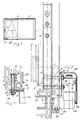
- Fig. 2 in vergrößertem Maßstab abgebrochen einen Vertikalschnitt im Bereich des schließseitigen Ausstellarms,
- Fig. 3 einen ebenfalls abgebrochenen Schnitt durch den Beschlag im Bereich der Verschraubung.
- 1 is a front view of a window with two sashes, one of which is equipped with at least one fitting according to the invention,
- 2 broken off on an enlarged scale a vertical section in the region of the closing arm,
- Fig. 3 is also a broken section through the fitting in the area of the screw.
In einen festen Rahmen 1 sind nebeneinanderliegend zwei Flügel 2 und 3 eingesetzt. Beim Flügel 2 handelt es sich in bevorzugter Weise um ein sogenanntes festes Feld, also einen Flügel, der nicht geöffnet wird. Der Flügel 3 ist beim Ausführungsbeispiel wenigstens um eine obere horizontale Achse klappbar und darüber hinaus auch an seinem oberen Ende ausstellbar, d.h. insgesamt parallelabstellbar. Des weiteren kann er zumindest in der Prallelabstellage im Sinne des Pfeils 4 verschoben, also vor das feste Feld 2 gebracht werden. Er ist sowohl an seinem unteren als auch an seinem oberen Ende derart mit dem festen Rahmen 1 verbunden, daß diese Öffnungsarten und auch das seitliche Verschieben möglich sind. Beispielsweise ist er an seinem unteren Ende mit zwei der erfindungsgemäßen Beschläge ausgestattet und auch an seinem oberen Ende können zwei Ausstellarme oder aber eine Ausstellschere die Verbindung zum festen Rahmen schaffen. Insoweit ist die Abstützung und Längsführung am oberen Ende von bekannter Art.In a fixed
Über eine Umschaltgetriebe 5, beispielsweise ein Dreistellungsgetriebe, wird der Flügel entriegelt und anschließend gekippt bzw. parallelabgestellt oder zumindest in entsprechende Bereitschaftsstellungen überführt. Hierzu notwendige nicht näher dargestellte Treibstangen sind mittels Stulpschienen abgedeckt, wobei in Fig. 2 eine vertikale Stulpschiene bzw. der vertikale Schenkel einer Stulpschiene einer Eckumlenkung mit 6 bezeichnet ist. Insbesondere an dessen in Gebrauchslage unterem Ende ist ein Versteifungsteil 7 befestigt, beispielsweise angenietet oder angeschweißt. Es handelt sich dabei um ein klotzförmiges Element, welches beim Ausführungsbeispiel zwei übereinanderliegende Gewindebohrungen 8 und 9 aufweist. Jede dient zur Aufnahme eines Gewindebolzen 10 bzw. 11 oder auch einer Schraube, wobei auf das stulpschienenferne Ende jedes Gewindebolzens eine Mutter 12 bzw. 13 aufgeschraubt ist. Wenn man das Versteifungsteil beispielsweise winkelförmig gestaltet, so kann es die betreffende Flügelecke umfassen und auch noch am horizontalen Schenkel befestigt werden. Dies verbessert die Aussteifung.The sash is unlocked via a change-over gear 5, for example a three-position gear, and then tilted or parked in parallel or at least transferred to the corresponding ready positions. Necessary driving rods, not shown for this purpose, are covered by cuff rails, wherein a vertical cuff rail or the vertical leg of a cuff rail of a corner deflection is designated by 6 in FIG. 2. In particular, a
Die beiden Gewindebolzen durchsetzen nicht nur entsprechende Profilbohrungen 14 und 15, insbesondere des Flügelüberschlags 16 des schließseitigen vertikalen Flügelholms 17, sondern auch in Verlängerung dazu verlaufende Bohrungen einer Befestigungsplatte 18 eines Lager-Beschlagteils 19. An letzterem ist das flügelseitige Ende eines Ausstellarms 20 drehbar gelagert. In der Zeichnung ist der schließseitige untere Ausstellarm zu sehen. Das festrahmenseitige Ende des Ausstellarms ist mit einem Laufwagen 21 drehbar verbunden, der auf einer Laufschiene 22 verschiebbar gelagert ist, welche gemäß Fig. 2 mit dem unteren Querholm des festen Rahmens 1 verbunden sein kann. Aufgrund der Verwendung dieses Ausstellarmes bzw. beim Ausführungsbeispiel zweier, den unteren Flügelecken zugeordneten Ausstellarme, kann der Flügel an seinem unteren Ende ausgestellt bzw. parallelabgestellt werden.The two threaded bolts not only pass through corresponding profile bores 14 and 15, in particular the wing flap 16 of the closing
Das Lager-Beschlagteil 19 bzw. dessen Befestigungsplatte oder -wand ist unten mit einer Anschlagleiste 23 versehen, welche die untere Stirnkante des Flügels, insbesondere des Flügelüberschlags untergreift. Diese Ausbildung dient in erster Linie der Montagevereinfachung.The bearing
Der Flügel ist ebenso wie der Rahmen aus einzelnen Profilen aufgebaut, insbesondere aus Kunststoffprofilen. Dies ergibt sich besonders deutlich aus Fig. 3 Die vier, einen Rahmen bildenden Profile sind im Eckbereich miteinander verbunden, im Falle von Kunststoff miteinander verschweißt. Die Profile können mit Versteifungen 24 versehen sein, jedoch kann man diese Versteifungen wegen des Verschweißungsvorganges nicht bis an die Schweißnaht heranführen. Um nun trotzdem die mit diesem Beschlag versehene Ecke verstärken zu können dabei insbesondere die Schweißnaht zu entlasten, verbindet man die Stulpschiene 6 über das Versteifungsteil 7 und die Bolzen 10, 11 mit dem Lager-Beschlagteil 19, welches ausschließlich oder in erster Linie mit dem unteren horizontalen Flügelquerholm verbunden wird. Dadurch werden die aus dem Flügelgewicht herrührenden, ein Verwinden des unteren Flügelquerholms bewirkenden Kräfte, auf den vertikalen Flügelquerholm übertragen. Diese Krafteinleitung am vertikalen Flügelholm wirkt der Verwindungskraft am unteren Flügelquerholm entgegen und schützt daher die Verbindungsstelle zwischen den beiden Holmen in diesem Eckbereich vor Überlastung und letztlich auch vor Beschädigung. Selbstverständlich treten diese Wirkungen auch bei Flügeln aus andersartigem Material ein, jedoch ist dort normalerweise die Verbindungsstelle nicht so kritisch wie bei Kunststoffprofilen. Es wird noch nachgetragen, daß die Beschlagteilnut für die Treibstange in Fig. 3 mit 25 bezeichnet ist und man dort die absatzartige Erweiterungen über zwei gegeneinanderweisende Profilstege bewirkt.Like the frame, the sash is constructed from individual profiles, in particular from plastic profiles. This can be seen particularly clearly from FIG. 3. The four profiles forming a frame are connected to one another in the corner region, and welded to one another in the case of plastic. The profiles can be provided with
Insbesondere aus Fig. 3 ersieht man, daß jeder Gewindebolzen 10, 11 mit einem Außenbund 26 ausgestattet ist, der zur Montage und/oder zur Versteifung herangezogen werden kann, wenn man ihn mit Schlüsselflächen versieht. Er liegt an der ins Rauminnere weisenden Fläche 27 des Flügels 3 an. Bei der Montage kann man zunächst die Gewindebolzen in die Gewinde 8 bzw. 9 des Versteifungsteils 7 so weit eindrehen, bis der Außenbund 26 jeweils an der Flügelinnenfläche 27 satt anliegt. Daraufhin steckt man auf die überstehenden freien Bolzenenden das Lager-Beschlagteil 19 auf und sichert es abschließend mit Hilfe der Muttern 12 bzw. 13. Weil die genannten, aus dem Gewicht des Flügels herrührenden Belastungen gleichermaßen auf die linke und recht untere Flügelecke wirken, ist es an sich nur folgerichtig, wenn beiden Flügelecken einen der erfindungsgemäßen Beschläge zuordnet. Dies setzt natürlich voraus, daß auch am rechten vertikalen Flügellängsholm (Fig. 1) die Möglichkeit zur Befestigung einer Stulpschiene besteht. Die beiden Lager-Beschlagteile 19 werden gemäß Fig. 1 mit einem gemeinsamen Abdeckprofil 28 verbunden, wobei insgesamt eine vor allen Dingen optisch sehr vorteilhafte Ausgestaltung entsteht. Das Abdeckprofil ist gemäß Fig. 2 von winkelförmiger Gestalt und es wird nach Überprüfung des komplett angeschlagenen Flügels auf die beiden Lager-Beschlagteile 19 aufgesprengt. Zu diesem Zwecke ist eine Verhakungs-Verbindung 29 am unteren Ende und eine Verrastverbindung 30 am oberen Ende vorgesehen.In particular, from Fig. 3 it can be seen that each threaded
Claims (11)
Priority Applications (1)
| Application Number | Priority Date | Filing Date | Title |
|---|---|---|---|
| AT88113824T ATE81182T1 (en) | 1987-10-23 | 1988-08-25 | FITTING FOR A LEAF OF A WINDOW, A DOOR OR. DGL. AND WINDOW OD. DOOR WITH THIS HARDWARE. |
Applications Claiming Priority (2)
| Application Number | Priority Date | Filing Date | Title |
|---|---|---|---|
| DE8714151U | 1987-10-23 | ||
| DE8714151U DE8714151U1 (en) | 1987-10-23 | 1987-10-23 |
Publications (3)
| Publication Number | Publication Date |
|---|---|
| EP0312738A2 true EP0312738A2 (en) | 1989-04-26 |
| EP0312738A3 EP0312738A3 (en) | 1990-09-26 |
| EP0312738B1 EP0312738B1 (en) | 1992-09-30 |
Family
ID=6813345
Family Applications (1)
| Application Number | Title | Priority Date | Filing Date |
|---|---|---|---|
| EP88113824A Expired - Lifetime EP0312738B1 (en) | 1987-10-23 | 1988-08-25 | Mounting for a wing of a window, door or the like swinging out at least at the bottom and window or door equipped with that mounting |
Country Status (3)
| Country | Link |
|---|---|
| EP (1) | EP0312738B1 (en) |
| AT (1) | ATE81182T1 (en) |
| DE (2) | DE8714151U1 (en) |
Cited By (4)
| Publication number | Priority date | Publication date | Assignee | Title |
|---|---|---|---|---|
| EP0443176A1 (en) * | 1990-02-19 | 1991-08-28 | Gretsch-Unitas GmbH Baubeschläge | At least sliding wing of a window, door or the like |
| EP1132562A2 (en) | 2000-03-11 | 2001-09-12 | W. HAUTAU GmbH | Corner reinforcements or struts for sliding wings |
| WO2017144193A1 (en) * | 2016-02-22 | 2017-08-31 | Siegenia-Aubi Kg | Lift-out protection device for a leaf, which can be moved in a parallel manner, in the form of a sliding and tilting leaf or a sliding leaf |
| WO2019034425A1 (en) * | 2017-08-16 | 2019-02-21 | Roto Frank Ag | Fitting comprising a carriage with a rigid connection locking device |
Families Citing this family (3)
| Publication number | Priority date | Publication date | Assignee | Title |
|---|---|---|---|---|
| DE8714151U1 (en) * | 1987-10-23 | 1987-12-03 | Gretsch-Unitas Gmbh Baubeschlaege, 7257 Ditzingen, De | |
| EP1048810A3 (en) | 1999-04-30 | 2001-11-28 | Gretsch-Unitas GmbH Baubeschläge | Carriage for a parallel sliding and tiltable fitting of a building window or building door as well as a building window or building door with such a fitting |
| EP1391576B1 (en) | 2002-06-28 | 2008-05-28 | HAUTAU GmbH | Torsion compensation for wings movable from one plane to another parallel plane |
Citations (6)
| Publication number | Priority date | Publication date | Assignee | Title |
|---|---|---|---|---|
| DE8308201U1 (en) * | 1983-03-19 | 1983-07-21 | Gretsch-Unitas GmbH Baubeschläge, 7257 Ditzingen | AT LEAST AT THE LOWER END EXTENDABLE WING OF A WINDOW, DOOR OR. DGL. |
| EP0119433A2 (en) * | 1983-03-19 | 1984-09-26 | Gretsch-Unitas GmbH Baubeschläge | Fitting for a wing of a window, door or the like, which is at least tiltable and movable from one plane to a second parallel plane |
| DE8704662U1 (en) * | 1987-03-28 | 1987-06-19 | Gretsch-Unitas Gmbh Baubeschlaege, 7257 Ditzingen, De | |
| DE8709299U1 (en) * | 1987-07-06 | 1987-08-27 | W. Hautau Gmbh, 3068 Helpsen, De | |
| DE8714151U1 (en) * | 1987-10-23 | 1987-12-03 | Gretsch-Unitas Gmbh Baubeschlaege, 7257 Ditzingen, De | |
| DE8804738U1 (en) * | 1988-04-11 | 1988-05-26 | W. Hautau Gmbh, 3068 Helpsen, De |
-
1987
- 1987-10-23 DE DE8714151U patent/DE8714151U1/de not_active Expired
-
1988
- 1988-08-25 DE DE8888113824T patent/DE3875055D1/en not_active Expired - Fee Related
- 1988-08-25 EP EP88113824A patent/EP0312738B1/en not_active Expired - Lifetime
- 1988-08-25 AT AT88113824T patent/ATE81182T1/en not_active IP Right Cessation
Patent Citations (6)
| Publication number | Priority date | Publication date | Assignee | Title |
|---|---|---|---|---|
| DE8308201U1 (en) * | 1983-03-19 | 1983-07-21 | Gretsch-Unitas GmbH Baubeschläge, 7257 Ditzingen | AT LEAST AT THE LOWER END EXTENDABLE WING OF A WINDOW, DOOR OR. DGL. |
| EP0119433A2 (en) * | 1983-03-19 | 1984-09-26 | Gretsch-Unitas GmbH Baubeschläge | Fitting for a wing of a window, door or the like, which is at least tiltable and movable from one plane to a second parallel plane |
| DE8704662U1 (en) * | 1987-03-28 | 1987-06-19 | Gretsch-Unitas Gmbh Baubeschlaege, 7257 Ditzingen, De | |
| DE8709299U1 (en) * | 1987-07-06 | 1987-08-27 | W. Hautau Gmbh, 3068 Helpsen, De | |
| DE8714151U1 (en) * | 1987-10-23 | 1987-12-03 | Gretsch-Unitas Gmbh Baubeschlaege, 7257 Ditzingen, De | |
| DE8804738U1 (en) * | 1988-04-11 | 1988-05-26 | W. Hautau Gmbh, 3068 Helpsen, De |
Cited By (8)
| Publication number | Priority date | Publication date | Assignee | Title |
|---|---|---|---|---|
| EP0443176A1 (en) * | 1990-02-19 | 1991-08-28 | Gretsch-Unitas GmbH Baubeschläge | At least sliding wing of a window, door or the like |
| EP1132562A2 (en) | 2000-03-11 | 2001-09-12 | W. HAUTAU GmbH | Corner reinforcements or struts for sliding wings |
| EP1132562A3 (en) * | 2000-03-11 | 2003-08-06 | W. HAUTAU GmbH | Corner reinforcements or struts for sliding wings |
| DE10110722B4 (en) * | 2000-03-11 | 2015-09-24 | Hautau Gmbh | Fitting for a sliding sash |
| WO2017144193A1 (en) * | 2016-02-22 | 2017-08-31 | Siegenia-Aubi Kg | Lift-out protection device for a leaf, which can be moved in a parallel manner, in the form of a sliding and tilting leaf or a sliding leaf |
| WO2019034425A1 (en) * | 2017-08-16 | 2019-02-21 | Roto Frank Ag | Fitting comprising a carriage with a rigid connection locking device |
| CN111108258A (en) * | 2017-08-16 | 2020-05-05 | 诺托弗朗克门窗技术有限公司 | Accessory including a tackle with rigid lift protection |
| CN111108258B (en) * | 2017-08-16 | 2021-09-14 | 诺托弗朗克门窗技术事业部 | Accessory including a tackle with rigid lift protection |
Also Published As
| Publication number | Publication date |
|---|---|
| EP0312738B1 (en) | 1992-09-30 |
| DE3875055D1 (en) | 1992-11-05 |
| DE8714151U1 (en) | 1987-12-03 |
| EP0312738A3 (en) | 1990-09-26 |
| ATE81182T1 (en) | 1992-10-15 |
Similar Documents
| Publication | Publication Date | Title |
|---|---|---|
| EP0119434B1 (en) | Wing of a window, door or the like movable out of its plane, at least at its lower edge | |
| DE4240416A1 (en) | Stiffener for door section of vehicle bodywork - uses variable length support beam with ends which engage door post recesses | |
| DE3645338C2 (en) | Concealed window hinge fitting | |
| EP0010144A1 (en) | Articulated fitting for windows, doors or the like | |
| EP0312738B1 (en) | Mounting for a wing of a window, door or the like swinging out at least at the bottom and window or door equipped with that mounting | |
| EP0201717A2 (en) | Fitting for a wing of a window, door or the like, which can at least be moved from one plane to another parallel plane | |
| EP0276678B1 (en) | Fitting for an at least pivoting door, window or the like | |
| DE1584080A1 (en) | Suspension for swing doors | |
| EP0231498B2 (en) | Fittings for a wing of a window, door or the like which is at least tiltable | |
| EP0844348B1 (en) | Hinge for doors or windows | |
| DE3900455C2 (en) | Roof boxes for motor vehicles | |
| EP0725202B1 (en) | Reinforcement for doors or windows | |
| DE4439475C1 (en) | Window mechanism for slide and tilt action | |
| EP1391576B1 (en) | Torsion compensation for wings movable from one plane to another parallel plane | |
| DE2520668A1 (en) | Actuated rod system for windows and doors - has top hat cross section covering profile for actuating rods | |
| EP0246431A2 (en) | Checking device for a tilting wing, especially for a tilting and pivoting wing, or sliding and tilting wing of windows, doors or the like | |
| EP0853912B1 (en) | Shower partition | |
| DE102021115490B4 (en) | Locking device for doors hinged on both sides | |
| EP0342420B1 (en) | Locking device at a sliding folding door or window | |
| EP0046821A1 (en) | Fittings for a sky-light | |
| EP3674568B1 (en) | Fitting for a partition wall system, especially for glass partitions | |
| CH655762A5 (en) | Folding sliding part for external and internal walls of buildings | |
| EP1170448A1 (en) | Carriage for a parallel sliding and tiltable fitting of a building window or building door as well as a building window or building door with such a fitting | |
| DE2932865A1 (en) | Roof window wing fitting - has torsion spring assembly connected to one frame and force locked to other | |
| EP0406914B1 (en) | Fitting for a tiltable frame of a window, door or similar |
Legal Events
| Date | Code | Title | Description |
|---|---|---|---|
| PUAI | Public reference made under article 153(3) epc to a published international application that has entered the european phase |
Free format text: ORIGINAL CODE: 0009012 |
|
| AK | Designated contracting states |
Kind code of ref document: A2 Designated state(s): AT DE FR GB |
|
| PUAL | Search report despatched |
Free format text: ORIGINAL CODE: 0009013 |
|
| AK | Designated contracting states |
Kind code of ref document: A3 Designated state(s): AT DE FR GB |
|
| 17P | Request for examination filed |
Effective date: 19901004 |
|
| 17Q | First examination report despatched |
Effective date: 19920213 |
|
| GRAA | (expected) grant |
Free format text: ORIGINAL CODE: 0009210 |
|
| AK | Designated contracting states |
Kind code of ref document: B1 Designated state(s): AT DE FR GB |
|
| REF | Corresponds to: |
Ref document number: 81182 Country of ref document: AT Date of ref document: 19921015 Kind code of ref document: T |
|
| GBT | Gb: translation of ep patent filed (gb section 77(6)(a)/1977) | ||
| REF | Corresponds to: |
Ref document number: 3875055 Country of ref document: DE Date of ref document: 19921105 |
|
| ET | Fr: translation filed | ||
| PLBE | No opposition filed within time limit |
Free format text: ORIGINAL CODE: 0009261 |
|
| STAA | Information on the status of an ep patent application or granted ep patent |
Free format text: STATUS: NO OPPOSITION FILED WITHIN TIME LIMIT |
|
| PG25 | Lapsed in a contracting state [announced via postgrant information from national office to epo] |
Ref country code: GB Effective date: 19930825 Ref country code: AT Effective date: 19930825 |
|
| 26N | No opposition filed | ||
| GBPC | Gb: european patent ceased through non-payment of renewal fee |
Effective date: 19930825 |
|
| PG25 | Lapsed in a contracting state [announced via postgrant information from national office to epo] |
Ref country code: FR Effective date: 19940429 |
|
| PG25 | Lapsed in a contracting state [announced via postgrant information from national office to epo] |
Ref country code: DE Effective date: 19940503 |
|
| REG | Reference to a national code |
Ref country code: FR Ref legal event code: ST |