EP0725202B1 - Reinforcement for doors or windows - Google Patents
Reinforcement for doors or windows Download PDFInfo
- Publication number
- EP0725202B1 EP0725202B1 EP95120728A EP95120728A EP0725202B1 EP 0725202 B1 EP0725202 B1 EP 0725202B1 EP 95120728 A EP95120728 A EP 95120728A EP 95120728 A EP95120728 A EP 95120728A EP 0725202 B1 EP0725202 B1 EP 0725202B1
- Authority
- EP
- European Patent Office
- Prior art keywords
- frame
- counter bearing
- strips
- limb
- reinforcement according
- Prior art date
- Legal status (The legal status is an assumption and is not a legal conclusion. Google has not performed a legal analysis and makes no representation as to the accuracy of the status listed.)
- Expired - Lifetime
Links
Images


Classifications
-
- E—FIXED CONSTRUCTIONS
- E05—LOCKS; KEYS; WINDOW OR DOOR FITTINGS; SAFES
- E05D—HINGES OR SUSPENSION DEVICES FOR DOORS, WINDOWS OR WINGS
- E05D5/00—Construction of single parts, e.g. the parts for attachment
- E05D5/02—Parts for attachment, e.g. flaps
-
- E—FIXED CONSTRUCTIONS
- E06—DOORS, WINDOWS, SHUTTERS, OR ROLLER BLINDS IN GENERAL; LADDERS
- E06B—FIXED OR MOVABLE CLOSURES FOR OPENINGS IN BUILDINGS, VEHICLES, FENCES OR LIKE ENCLOSURES IN GENERAL, e.g. DOORS, WINDOWS, BLINDS, GATES
- E06B1/00—Border constructions of openings in walls, floors, or ceilings; Frames to be rigidly mounted in such openings
- E06B1/04—Frames for doors, windows, or the like to be fixed in openings
- E06B1/52—Frames specially adapted for doors
-
- E—FIXED CONSTRUCTIONS
- E06—DOORS, WINDOWS, SHUTTERS, OR ROLLER BLINDS IN GENERAL; LADDERS
- E06B—FIXED OR MOVABLE CLOSURES FOR OPENINGS IN BUILDINGS, VEHICLES, FENCES OR LIKE ENCLOSURES IN GENERAL, e.g. DOORS, WINDOWS, BLINDS, GATES
- E06B3/00—Window sashes, door leaves, or like elements for closing wall or like openings; Layout of fixed or moving closures, e.g. windows in wall or like openings; Features of rigidly-mounted outer frames relating to the mounting of wing frames
- E06B3/70—Door leaves
- E06B3/82—Flush doors, i.e. with completely flat surface
- E06B3/822—Flush doors, i.e. with completely flat surface with an internal foursided frame
-
- E—FIXED CONSTRUCTIONS
- E06—DOORS, WINDOWS, SHUTTERS, OR ROLLER BLINDS IN GENERAL; LADDERS
- E06B—FIXED OR MOVABLE CLOSURES FOR OPENINGS IN BUILDINGS, VEHICLES, FENCES OR LIKE ENCLOSURES IN GENERAL, e.g. DOORS, WINDOWS, BLINDS, GATES
- E06B3/00—Window sashes, door leaves, or like elements for closing wall or like openings; Layout of fixed or moving closures, e.g. windows in wall or like openings; Features of rigidly-mounted outer frames relating to the mounting of wing frames
- E06B3/96—Corner joints or edge joints for windows, doors, or the like frames or wings
- E06B3/964—Corner joints or edge joints for windows, doors, or the like frames or wings using separate connection pieces, e.g. T-connection pieces
- E06B3/9641—Corner joints or edge joints for windows, doors, or the like frames or wings using separate connection pieces, e.g. T-connection pieces part of which remains visible
-
- E—FIXED CONSTRUCTIONS
- E05—LOCKS; KEYS; WINDOW OR DOOR FITTINGS; SAFES
- E05Y—INDEXING SCHEME RELATING TO HINGES OR OTHER SUSPENSION DEVICES FOR DOORS, WINDOWS OR WINGS AND DEVICES FOR MOVING WINGS INTO OPEN OR CLOSED POSITION, CHECKS FOR WINGS AND WING FITTINGS NOT OTHERWISE PROVIDED FOR, CONCERNED WITH THE FUNCTIONING OF THE WING
- E05Y2900/00—Application of doors, windows, wings or fittings thereof
- E05Y2900/10—Application of doors, windows, wings or fittings thereof for buildings or parts thereof
- E05Y2900/13—Application of doors, windows, wings or fittings thereof for buildings or parts thereof characterised by the type of wing
- E05Y2900/132—Doors
-
- E—FIXED CONSTRUCTIONS
- E05—LOCKS; KEYS; WINDOW OR DOOR FITTINGS; SAFES
- E05Y—INDEXING SCHEME RELATING TO HINGES OR OTHER SUSPENSION DEVICES FOR DOORS, WINDOWS OR WINGS AND DEVICES FOR MOVING WINGS INTO OPEN OR CLOSED POSITION, CHECKS FOR WINGS AND WING FITTINGS NOT OTHERWISE PROVIDED FOR, CONCERNED WITH THE FUNCTIONING OF THE WING
- E05Y2900/00—Application of doors, windows, wings or fittings thereof
- E05Y2900/10—Application of doors, windows, wings or fittings thereof for buildings or parts thereof
- E05Y2900/13—Application of doors, windows, wings or fittings thereof for buildings or parts thereof characterised by the type of wing
- E05Y2900/148—Windows
-
- E—FIXED CONSTRUCTIONS
- E06—DOORS, WINDOWS, SHUTTERS, OR ROLLER BLINDS IN GENERAL; LADDERS
- E06B—FIXED OR MOVABLE CLOSURES FOR OPENINGS IN BUILDINGS, VEHICLES, FENCES OR LIKE ENCLOSURES IN GENERAL, e.g. DOORS, WINDOWS, BLINDS, GATES
- E06B3/00—Window sashes, door leaves, or like elements for closing wall or like openings; Layout of fixed or moving closures, e.g. windows in wall or like openings; Features of rigidly-mounted outer frames relating to the mounting of wing frames
- E06B3/70—Door leaves
- E06B2003/7046—Door leaves with provisions for locks, hinges or other fittings
-
- E—FIXED CONSTRUCTIONS
- E06—DOORS, WINDOWS, SHUTTERS, OR ROLLER BLINDS IN GENERAL; LADDERS
- E06B—FIXED OR MOVABLE CLOSURES FOR OPENINGS IN BUILDINGS, VEHICLES, FENCES OR LIKE ENCLOSURES IN GENERAL, e.g. DOORS, WINDOWS, BLINDS, GATES
- E06B3/00—Window sashes, door leaves, or like elements for closing wall or like openings; Layout of fixed or moving closures, e.g. windows in wall or like openings; Features of rigidly-mounted outer frames relating to the mounting of wing frames
- E06B3/70—Door leaves
- E06B2003/7059—Specific frame characteristics
- E06B2003/7074—Metal frames
- E06B2003/7076—Metal frames insulated
Definitions
- the invention relates to reinforcement on doors or windows, with a fixed frame to be arranged with an abutment bar with a cover leg rests on a frame side of the frame, from which an abutment leg vertically and lengthways engages continuously in the frame, with a fishing pin the hinge of a wing screwed into the abutment leg is.
- Such reinforcement is known from DE 43 19 945 A1.
- a fishing pin becomes one in the abutment leg Angel screwed in, with which a window sash rotates on Frame is stored.
- the known reinforcement is V-shaped formed, with an angle leg the abutment leg and the other leg forms the cover leg.
- Such reinforcement only needs to be thin-walled to be the loads on window sashes record, especially since her abutment leg in one comparatively strong frame frame is embedded.
- only one type of reinforcement is used comparatively low stiffening effect in the area of Frame.
- the pull-out forces are also one in the abutment leg screwed fastener comparatively low.
- the invention is therefore based on the object to improve the abutment strip in such a way that the Frame or its receiving the abutment bar Frame frame significantly reinforced and stiffened when the frame is designed in particular as a wooden frame.
- the abutment leg is formed by a hollow chamber profile.
- the hollow chamber profile of the abutment leg causes a significant Stiffening of the frame leg.
- the abutment ledge is special due to its training with a hollow chamber profile inherently rigid. It is therefore for use with such Frame suitable, which itself has sufficient inherent rigidity or lack strength. For example apply to wooden frames.
- the hollow chamber profile the advantage that fishing pins when screwing them in can be attached in two walls, what the burglary security against prying in the fishing area significantly increases.
- the hollow chamber profile enables the abutment bar also, stable internals such as, for example, protruding pins on the fold side against the vertical prying open of the casement.
- the training go as far as, for example, wooden frames, but also with plastic frames that the two sides of the Hollow chamber profile remaining wall thicknesses of the wood or Plastic frame just like a cladding, while the strength of the construction from the abutment ledge is effected, which, of course, firmly with the Frame frame must be assembled.
- the reinforcement that the abutment leg in the cross section in the center of the cover leg protrudes by comparison at its edges short, parallel frame engagement strips to the abutment leg having.
- the abutment bar receives a substantial one Rigidity also in the area of your cover leg, with the for example the entire fold-side surface of a frame leg can be covered and bordered.
- the reinforcement is designed that within the abutment leg parallel to each other Transverse webs are arranged at a distance from one another, which allows fasteners to be screwed in.
- the corner brackets can be used with the abutment strips be coupled in a known manner, e.g. by Press in or glue in.
- Fasteners can be used in the reinforcement larger pull-out forces are provided that the spacer bars and their parallel strips of a hollow frame profile of the door or window sash and / or the crossbars of the abutment leg on each other facing surfaces longitudinal thread retaining ribs exhibit.
- the engaging in the thread holding ribs Fasteners can not only be anchored more firmly, but also more easily, for example by not using self-tapping Screws must be used.
- the thread retaining ribs are completely unproblematic to manufacture, because it extrudes in one piece with the hollow frame profiles can be.
- the reinforcement can be developed in such a way that you Frame hollow profile of the wing is assigned in parallel, that has a groove open on the rabbet side, into the engagement bores having elements or closure elements acting on the frame side are permanently installed.
- the groove which is open on the rabbet side, is a proven construction tool, to accommodate fittings with which sash adjustment functions be performed.
- Such an actuating function is the locking function in which the casement with locking bolts actuated by the locking rod fitting Swing and / or tilt opening coupled to the frame becomes.
- other closure elements can also be installed, such as Latches, latches or locks.
- Such elements can be advantageous installed using an open groove on the rebate side become.
- Such a groove open on the fold side is also for this suitable for receiving elements with engagement bores, for example, with cuff rails with holes, in whose holes or engaging holes engage bolts that are fixed on the frame side and when the Prevent the wing from levering out vertically.
- a design of the reinforcement is characterized by that the frame hollow profile at least one of each Protruding spacer bar on the inner surface of a side wall for a lock case, the lock latch and / or -Bar engages in the abutment leg. With the spacer bar is achieved that the lock case within of the frame hollow profile can not twist if the Wings are pried open in the event of an attempted break-in should. At the same time, the engagement of the lock latch and / or the lock bolt in the abutment leg a stable Counter bearing reached, regardless of the height of the installation site of the lock in the frame profile.
- the hollow frame profiles are also designed to be as burglar-resistant as possible, its connectors and the abutment ledge Metal.
- the sash has a correspondingly high inherent rigidity, also in the joint area of the hollow frame profiles or the connector. This inherent rigidity is beyond the scope of the frame roughly evenly distributed. A corresponding there is also an even distribution of inherent rigidity in the area of the abutment bar, if this extends over the circumference the frame is closed.
- the reinforcement can be designed the frame profile outwardly projecting fastening strips for fittings or for cladding parts, wherein the fastening strips a side wall if necessary over the fold side Project the frame area to form a rollover.
- the exterior can be designed influence the sash largely.
- the mounting strips can use the mounting strips to fix fittings serve like wing fishing.
- the mounting strips serve to fasten cladding parts, such as bezels that change the look of the Sash frame can be designed.
- the sash is therefore especially for the craft area very interesting in the individual Refinements are particularly in demand.
- the fastening strips are not only used to design the door, that they hold or attach cladding parts allow, but they are also door-shaping in that the fastening strips of a side wall over the fold side Project the frame area to form a rollover.
- the rollover forming board of fastening strips allowed the cover of the rebate space between the casement and Frame, as well as the use of conventional fittings, for example the use of standard door hinges with fishing bolts.
- frame rollovers are formed Find boards of the fastening strips inside the room.
- a door leaf is shown schematically, the Door leaf 36 halfway up the door handle fitting 43 is shown broken away, so that the door leaf frame can recognize.
- This consists of four right angles mutually arranged frame hollow profiles 10, which each have two ends 10 'coupled via a connector 12 are.
- Each hollow frame section 10 has two cut to length Ends 10 'and, accordingly, two joints 11.
- the connectors 12 in turn have at the joints 11 of the hollow frame profiles 10 adjacent abutting surfaces 15, the outer contour is profiled as well as the outer contour of the hollow frame profiles 10th
- the frame hollow profiles 10 in arranged on the same frame level and close between them a frame fill 14 that suits the needs can be designed differently.
- the side walls 17 of the Hollow frame profiles 10 of a frame side each lie in the same Level, so that 10 cladding panels on the outside of the frame hollow sections 21 can be attached, both wing inside, as well as outside.
- each frame hollow profile 10 consists of two Half shells, which essentially form the side walls 17 and are held together by components 33.
- This Components 33 are longitudinal strips from bad thermally conductive material, so that on one side of a Frame hollow profile 10 approximately existing temperature conditions not by conduction to the opposite one, for example, half-shell lying on the inside of the wing can.
- Such a design and use poorly heat-conducting components 33 can also be dispensed with, if the frame hollow profiles 10 or the wing otherwise are sufficiently insulated or covered with thermal insulation.
- the hollow frame profiles 10 have a frame, so on its fold-side frame surface 24, a longitudinally running one Groove 13 as a functional profile.
- This groove 13 is used for example the arrangement of an espagnolette fitting Actuation of locking bolts and the like In the area of the groove 13 can also be used other closure elements If necessary, couple the casement to the frame should.
- a lock case 45 is dashed shown, the lock with its lock latch as a closure element 18 in an abutment strip 40 vertical frame spar 39 engages.
- the lock case 45 is within a hollow frame section 10 against lateral movements supported towards the side walls 17.
- the central web 44 on the Installation location of the lock case 45 removed accordingly, e.g. by milling, so that the screw-in strips present on the central web 44 29, which are still shown in Figure 3, omitted.
- the central web 44 becomes two spacer bars 59.
- the 45 adjacent to the lock case interior of a pair of terminal blocks 32 can the lock case 45 also support if the lock case width the Distance between two adjacent terminal strips 32 each other opposite side walls 17 is dimensioned accordingly.
- the parallel bars 60 are parallel to the spacer bars 59 arranged, namely at a distance 61 that the screwing of fasteners allowed.
- fasteners are, for example, screws.
- the screws screw-on tapes can be set, for example are designed as holding plates for a casement.
- the Hollow frame profile 10 can be used when using several spacer bars 59 and parallel strips 60 are designed so that different distances can be achieved, for example additionally also the distance 61 'in the area of the central web 44.
- the frame profiles 10 point from their side walls 17 from transversely protruding mounting strips 19.20.
- the mounting bar 19 stands in relation to the frame side on the rebate side 24 back.
- the mounting bar 20 is related on the fold-side frame surface 24. As a result, forms the side wall 17 on the fold side or on the cover frame overlap side a sealing surface 47, see FIG. 6, on which according to FIG to 4 is a seal 48 with a sealing lip, wherein the seal 48 in a longitudinal groove 49 of the Frame is set.
- the mounting bar 20 is due to an extension 50 of the side wall 17 so far that a rollover 51st is formed with which the rebate space 52 is covered on the inside of the wing becomes.
- the mounting strips 19,20 run the length of the Hollow frame profiles through and can accommodate cladding parts to serve.
- the Fig.2 to 4 show inside and wing -covering 21 arranged on the outside between two opposite mounting strips 19 outside or 20 inside.
- the cladding panels 21 span the entire Width and height of the casement, including the frame fill 14.
- the cladding panels 21 are designed so that with them the appearance of the entire door or casement frame wing can be influenced. Are there the mounting strips 19 behind the rollovers 53 of the Frame spars 39 arranged so that the frame outside Visible surface 22 only the outer view of the wing certainly.
- the visible surface 22 of the inner paneling panel 21 is on its edges from the mounting strips 20 as well as the wing outer panel 21.
- the mounting strips 19, 20 are each approximately L-shaped, the short L-leg lies flush with the visible surface 22. But this is only on the inside of the wing visible and could also be avoided if desired by the mounting strips 20 in the edges of the Cladding panel 21 can be inserted.
- FIG.4 Another way to influence the view the wing frame surface on the inside of the wing consists of to provide this with a formwork 23, which in Fig.4 is shown.
- This view formwork 23 clad the Cover plate 21 and its outer edges, the fastening strips 19.20 are used in recesses 54 can and wherein the cladding panel 21 is also screw-free can be kept, such as outside of the wing or in all cases of Fig. 2,3.
- fishing 38 can be used with the fishing pin designed as a screw pin 35 through the fastening strip 20 or its formwork 23 installed in the panel 21 become.
- the cladding panel or the fastening strip 20 in the area of the trim panel 21 with a Abutment 37 to increase the screw-in security of the fishing pin 35 be provided, which was indicated in Figure 4.
- the other fishing pin 41 of the fishing 38 is also as Screw pin formed and in an abutment bar 40th screwed into the frame spar from the rebate space 52 39 inserted and attached to it, e.g. by screwing.
- the abutment strip 40 is designed as a hollow chamber profile and its abutment leg 62 has two walls 42, that are parallel to each other at a distance.
- the walls 42 are inside of the frame with a continuous Web 63 connected, while a cover leg on the rebate side 55 is present, the essential area of the rebate side Occupies frame area and in this way the burglar resistance serves.
- the T-shaped design of the abutment bar 40 means a significant increase in the dimensional stability of the frame spar 39. For this is the abutment bar 40 also specially designed for the rest.
- the cover leg 55 has the abutment leg 62 at its ends 63 parallel frame engaging strips 64, from the rebate space 52 intervene in the material of the frame spar 53 and so ensure that the cover leg 55 is not transverse to this Frame engagement bars 64 can be moved. Together with the abutment leg 32 results in an improved Definition of the entire abutment bar 40.
- the cross-section of the hollow chamber the abutment bar 40 or the abutment leg 62 is considerably stiffened by the fact that within the Abutment leg 62 parallel crossbars 65 present are.
- the transverse webs 65 fulfill their stiffening function addition another function by working in a Distance are arranged, the screwing of fasteners allowed.
- Such fasteners are, for example the fishing pin 41 of fishing 38 to the bracket a door or window frame wing. A fishing pin 41 will then across the two walls 42 between the crosspieces 65 screwed through. The latter have turned towards each other Surfaces of longitudinally running thread holding ribs 66, as well as the spacer bars 59 shown in FIG. 6 and the parallel bars 60 assigned to them.
- the hollow chamber profile of the abutment bar 40 allows it, the reinforcement of a frame or its abutment strips 40 to be coupled together in the frame corner area.
- corner brackets 67 are used, the legs of each end engage in the interior of the abutment strips 40, that are adjacent to each other in the frame corner area and there for example, on a miter or butt joint lie.
- the between the cladding panels 21 and the hollow frame profiles 10 formed space is with the frame 14th provided that trained according to the technical requirements can be.
- the frame fill can, like that for example is indicated in Figure 2, from an inhomogeneous Structure exist. Instead, blocked ones can also be used Wooden strips or honeycomb structures can be used. Also one Insulating glass can be used when the cladding panel 21 leaves a corresponding section, in essentially only in the area of the hollow frame profiles 10 is present.
- both the frame filling 14, as well as the interior of the hollow frame profiles 10 in the desired Can be filled in, for example with heat and / or soundproofing material. It is also possible, to increase bullet resistance by using harder material is used, e.g. Liquid stone.
- the design of the hollow frame profiles results 10 a wide range of options, one Door or a door wing or a window wing too design that he on the one hand the technical requirements, on the other hand the optical requirements and moreover meet the burglar security requirements can.
- Fig.5a to 5d connector 12 used.
- This is essentially a prismatic or cuboid Component with two abutment surfaces 15, the outer contour with the outer contour of the hollow frame profiles 10 is identical. The can be seen in particular by comparing FIG. 5d with FIG. 6.
- the side surfaces 16 with the side walls 17 one Hollow frame profile 10.
- the connector 12 Since the frame hollow profile 10 according to Figure 6 several functional Has profiles, the connector 12 is corresponding customized. On the one hand, this applies to the groove 13, which with the same or similar profile also in the rebate side End faces 54 of the connector 12 is incorporated, that is in those end faces on which frame hollow profiles 10 not concern.
- these grooves 13 of the connector 12 it is possible in these grooves 13 of the connector 12 to arrange drive rod fittings, for example with a corner drive so that the sash can be operated with conventional hardware, for example with a one-hand fitting in training for Casement. Special corner or center locks from Sash frames are therefore with little technical effort possible and can the burglar resistance of the casement further increase.
- FIG. 5d Another functional profiling of the hollow frame profile 10 consists in the mounting strips 19.20.
- Appropriate Fastening strips 19, 20 are also shown in FIG. 5d Connector 12 present, the mounting strips 19.20 of the connector 12 with which the frame hollow profiles 10 are aligned.
- the connector 12 is structured such that it is a Has frame structure, so in the middle has mass-free areas. This is achieved by a lattice structure with lattice webs 30, which each have two opposing frame walls connect with each other and perpendicular to those Lattice webs 30, which are the other opposite one another Connect the frame walls together. According to the 5a, 5c there are a total of four lattice webs 30 which one piece with each other and with the frame of the connector 12 Form structure.
- fastening screws 27 For fastening the connector 12 to the frame profiles 10 serve fastening screws 27, through frame holes 57 into the parallel screw-in strips 29 be screwed in until the screw head is as indicated in Fig. 5c Assumes position and the abutting surface 15 against the joint 11 of the hollow frame section 10 pulls.
- the fastening screw 27 is, for example, a cylinder head screw with internal polygon, the head 28 dimensioned so is that the screw 27 through the recesses 26 can get into the position shown.
- an Allen key is a screw adjustment of the fastening screw 27 also possible if this at the beginning of their Intervention in the screw-in strips 29, for example be arranged in the middle cavity 34 of the connector 12 should.
- a frame hollow profile coupling connector 12 can also can be formed for more than two hollow frame profiles by all four narrow end faces designed as abutting surfaces 15 become.
- Such a connector can, for example, four in Hollow frame profiles arranged cross to one another connect what is important for larger casement structures is. In this case, another fastening technique used.
Landscapes
- Engineering & Computer Science (AREA)
- Civil Engineering (AREA)
- Structural Engineering (AREA)
- Mechanical Engineering (AREA)
- Joining Of Corner Units Of Frames Or Wings (AREA)
- Wing Frames And Configurations (AREA)
- Electrical Discharge Machining, Electrochemical Machining, And Combined Machining (AREA)
Abstract
Description
Die Erfindung bezieht sich auf eine Bewehrung an Türen oder Fenstern, mit einem ortsfest anzuordnenden Blendrahmen mit einer Widerlagerleiste, die mit einem Abdeckschenkel auf einer falzseitigen Blendrahmenfläche aufliegt, von dem aus ein Widerlagerschenkel senkrecht und längs durchlaufend in den Blendrahmen eingreift, wobei ein Angelzapfen der Angel eines Flügels in den Widerlagerschenkel eingeschraubt ist.The invention relates to reinforcement on doors or windows, with a fixed frame to be arranged with an abutment bar with a cover leg rests on a frame side of the frame, from which an abutment leg vertically and lengthways engages continuously in the frame, with a fishing pin the hinge of a wing screwed into the abutment leg is.
Eine derartige Bewehrung ist aus der DE 43 19 945 A1 bekannt. In den Widerlagerschenkel wird ein Angelzapfen einer Angel eingeschraubt, mit der ein Fensterflügel drehbar am Blendrahmen gelagert wird. Die bekannte Bewehrung ist V-winkelförmig ausgebildet, wobei ein Winkelschenkel den Widerlagerschenkel und der andere Schenkel den Abdeckschenkel bildet. Eine derartige Bewehrung braucht nur dünnwandig ausgebildet zu sein, um die an Fensterflügeln auftretenden Belastungen aufzunehmen, zumal ihr Widerlagerschenkel in einen vergleichsweise starken Blendrahmenschenkel eingelassen ist. Infolgedessen geht von einer derartigen Bewehrung nur eine vergleichsweise geringe Versteifungswirkung im Bereich des Blendrahmens aus. Auch sind die Auszugkräfte eines in den Widerlagerschenkel eingeschraubten Befestigungsmittels vergleichsweise gering. Such reinforcement is known from DE 43 19 945 A1. A fishing pin becomes one in the abutment leg Angel screwed in, with which a window sash rotates on Frame is stored. The known reinforcement is V-shaped formed, with an angle leg the abutment leg and the other leg forms the cover leg. Such reinforcement only needs to be thin-walled to be the loads on window sashes record, especially since her abutment leg in one comparatively strong frame frame is embedded. As a result, only one type of reinforcement is used comparatively low stiffening effect in the area of Frame. The pull-out forces are also one in the abutment leg screwed fastener comparatively low.
Der Erfindung liegt daher insoweit die Aufgabe zugrunde, die Widerlagerleiste dahingehend zu verbessern, daß sie den Blendrahmen bzw. dessen die Widerlagerleiste aufnehmenden Blendrahmenschenkel erheblich verstärkt und versteift, wenn der Blendrahmen insbesondere als Holzrahmen ausgebildet ist.The invention is therefore based on the object to improve the abutment strip in such a way that the Frame or its receiving the abutment bar Frame frame significantly reinforced and stiffened when the frame is designed in particular as a wooden frame.
Diese Aufgabe wird dadurch gelöst, daß der Widerlagerschenkel von einem Hohlkammerprofil gebildet ist. Das Hohlkammerprofil des Widerlagerschenkels bewirkt eine erhebliche Versteifung des Blendrahmenschenkels. Die Widerlagerleiste ist infolge ihrer Ausbildung mit einem Hohlkammerprofil besonders eigensteif. Sie ist daher zum Einsatz mit solchen Blendrahmen geeignet, die selbst eine ausreichende Eigensteifigkeit oder Festigkeit vermissen lassen. Das kann beispielsweise für Holzblendrahmen gelten. Zugleich hat das Hohlkammerprofil den Vorteil, daß Angelzapfen bei ihrem Einschrauben in zwei Wände besonders auszugfest angebracht werden können, was die Einbruchsicherheit gegen Aufhebeln im Angelbereich erheblich heraufsetzt. Letztlich ermöglicht das Hohlkammerprofil der Widerlagerleiste auch, stabile Einbauten vorzunehmen, wie beispielsweise falzseitig vorspringende Zapfen gegen das vertikale Aufhebeln des Flügelrahmens. Dabei kann die Ausbildung soweit gehen, beispielsweise bei Holzrahmen, aber auch bei Kunststoffrahmen, daß die beidseitig des Hohlkammerprofils verbleibenden Wandstärken des Holz- oder Kunststoffrahmens nur noch einer Verkleidung gleichkommen, während die Festigkeit der Konstruktion von der Widerlagerleiste bewirkt wird, die im übrigen natürlich fest mit dem Blendrahmenholm zusammengebaut sein muß.This object is achieved in that the abutment leg is formed by a hollow chamber profile. The hollow chamber profile of the abutment leg causes a significant Stiffening of the frame leg. The abutment ledge is special due to its training with a hollow chamber profile inherently rigid. It is therefore for use with such Frame suitable, which itself has sufficient inherent rigidity or lack strength. For example apply to wooden frames. At the same time, the hollow chamber profile the advantage that fishing pins when screwing them in can be attached in two walls, what the burglary security against prying in the fishing area significantly increases. Ultimately, the hollow chamber profile enables the abutment bar also, stable internals such as, for example, protruding pins on the fold side against the vertical prying open of the casement. Here can the training go as far as, for example, wooden frames, but also with plastic frames that the two sides of the Hollow chamber profile remaining wall thicknesses of the wood or Plastic frame just like a cladding, while the strength of the construction from the abutment ledge is effected, which, of course, firmly with the Frame frame must be assembled.
Besonders vorteilhaft ist es, die Bewehrung so auszubilden, daß der Widerlagerschenkel im Querschnitt mittig vom Abdeckschenkel vorspringt, der an seinen Kanten im Vergleich zum Widerlagerschenkel kurze, parallele Rahmeneingriffsleisten aufweist. Die Widerlagerleiste erhält eine erhebliche Steifigkeit auch im Bereich ihres Abdeckschenkels, mit dem beispielsweise die gesamte falzseitige Fläche eines Blendrahmenschenkels abgedeckt und eingefaßt werden kann. It is particularly advantageous to design the reinforcement that the abutment leg in the cross section in the center of the cover leg protrudes by comparison at its edges short, parallel frame engagement strips to the abutment leg having. The abutment bar receives a substantial one Rigidity also in the area of your cover leg, with the for example the entire fold-side surface of a frame leg can be covered and bordered.
Um die Auszugfestigkeit von Befestigungsmitteln wesentlich zu erhöhen, andererseits aber auch die Stabilität der Widerlagerleiste zu verbessern, wird die Bewehrung so ausgebildet, daß innerhalb des Widerlagerschenkels einander parallele Querstege in einem Abstand voneinander angeordnet sind, der das Einschrauben von Befestigungsmitteln erlaubt.To the pull-out strength of fasteners essential to increase, but also the stability of the To improve the abutment bar, the reinforcement is designed that within the abutment leg parallel to each other Transverse webs are arranged at a distance from one another, which allows fasteners to be screwed in.
Eine weitere erhebliche Verbesserung der Bewehrung im Blendrahmenbereich wird dadurch bewirkt, daß die Widerlagerleisten zweier winkliger Blendrahmenholme von Eckwinkeln miteinander gekuppelt sind. Die Eckwinkel können mit den Widerlagerleisten in bekannter Weise gekuppelt werden, z.B. durch Einpressen oder Einkleben.Another significant improvement in reinforcement in The frame area is caused by the abutment strips two angled frame spars of corner brackets together are coupled. The corner brackets can be used with the abutment strips be coupled in a known manner, e.g. by Press in or glue in.
Befestigungsmittel können in der Bewehrung dadurch mit größeren Auszugkräften versehen werden, daß die Distanzhalteleisten und deren Parallelleisten eines Rahmenhohlprofils des Tür- oder Fensterflügels und/oder die Querstege des Widerlagerschenkels auf ihren einander zugekehrten Flächen längsdurchlaufende Gewindehalterippen aufweisen. Die in die Gewindehalterippen eingreifenden Befestigungsmittel lassen sich nicht nur fester verankern, sondern auch problemloser, indem beispielsweise keine selbstschneidenden Schrauben eingesetzt werden müssen. Andererseits sind die Gewindehalterippen völlig unproblematisch herzustellen, da sie mit den Rahmenhohlprofilen einstückig extrudiert werden können.Fasteners can be used in the reinforcement larger pull-out forces are provided that the spacer bars and their parallel strips of a hollow frame profile of the door or window sash and / or the crossbars of the abutment leg on each other facing surfaces longitudinal thread retaining ribs exhibit. The engaging in the thread holding ribs Fasteners can not only be anchored more firmly, but also more easily, for example by not using self-tapping Screws must be used. On the other hand the thread retaining ribs are completely unproblematic to manufacture, because it extrudes in one piece with the hollow frame profiles can be.
Die Bewehrung kann so weitergebildet werden, daß ihr ein Rahmenhohlprofil des Flügels parallel zugeordnet ist, das eine falzseitig offene Nut aufweist, in die Eingriffsbohrungen aufweisende Elemente oder blendrahmenseitig wirkende Verschlußelemente fest eingebaut sind.The reinforcement can be developed in such a way that you Frame hollow profile of the wing is assigned in parallel, that has a groove open on the rabbet side, into the engagement bores having elements or closure elements acting on the frame side are permanently installed.
Die falzseitig offene Nut ist ein an sich bewährtes Konstruktionsmittel, um Beschläge unterzubringen, mit denen Flügelstellfunktionen durchgeführt werden. Eine solche Stellfunktion ist die Verschlußfunktion, bei der der Flügelrahmen mit vom Teibstangenbeschlag betätigten Schließbolzen gegen Schwenk- und/oder Kippöffnen mit dem Blendrahmen gekoppelt wird. Außer solchen Verschlußelemente bildenden Schließbolzen können auch andere Verschlußelemente eingebaut werden, wie Riegel, Fallen bzw. Schlösser. Derartige Elemente können vorteilhaft unter Ausnutzung einer falzseitig offenen Nut eingebaut werden. Eine solche falzseitig offene Nut ist auch dafür geeignet, Eingriffsbohrungen aufweisende Elemente aufzunehmen, beispielsweise mit Löchern versehene Stulpschienen, in deren Löcher bzw. Eingriffsbohrungen Bolzen eingreifen, die blendrahmenseitig fixiert sind und bei Schließstellung des Flügels dessen vertikales Aushebeln verhindern.The groove, which is open on the rabbet side, is a proven construction tool, to accommodate fittings with which sash adjustment functions be performed. Such an actuating function is the locking function in which the casement with locking bolts actuated by the locking rod fitting Swing and / or tilt opening coupled to the frame becomes. Except for such locking elements forming locking bolts other closure elements can also be installed, such as Latches, latches or locks. Such elements can be advantageous installed using an open groove on the rebate side become. Such a groove open on the fold side is also for this suitable for receiving elements with engagement bores, for example, with cuff rails with holes, in whose holes or engaging holes engage bolts that are fixed on the frame side and when the Prevent the wing from levering out vertically.
Eine Ausgestaltung der Bewehrung ist dadurch gekennzeichnet, daß das Rahmenhohlprofil mindestens eine von jeder Innenfläche einer Seitenwand vorstehende Distanzhalteleiste für einen Schloßkasten aufweist, dessen Schloßfalle und/oder -Riegel in den Widerlagerschenkel eingreift. Mit der Distanzhalteleiste wird erreicht, daß sich der Schloßkasten innerhalb des Rahmenhohlprofils nicht verdrehen kann, wenn der Flügel im Falle eines Einbruchsversuchs aufgehebelt werden soll. Zugleich wird durch den Eingriff der Schloßfalle und/ oder des Schloßriegels in den Widerlagerschenkel ein stabiles Gegenlager erreicht, das unabhängig von der Höhe der Einbaustelle des Schlosses in das Rahmenprofil ist.A design of the reinforcement is characterized by that the frame hollow profile at least one of each Protruding spacer bar on the inner surface of a side wall for a lock case, the lock latch and / or -Bar engages in the abutment leg. With the spacer bar is achieved that the lock case within of the frame hollow profile can not twist if the Wings are pried open in the event of an attempted break-in should. At the same time, the engagement of the lock latch and / or the lock bolt in the abutment leg a stable Counter bearing reached, regardless of the height of the installation site of the lock in the frame profile.
Um den Flügelrahmen möglichst stabil und infolgedessen auch möglichst einbruchhemmend auszubilden, bestehen die Rahmenhohlprofile, seine Verbinder und die Widerlagerleiste aus Metall. Der Flügelrahmen besitzt eine entsprechend große Eigensteifigkeit, auch im Stoßbereich der Rahmenhohlprofile bzw. der Verbinder. Diese Eigensteifigkeit ist über den Rahmenumfang in etwa gleichmäßig verteilt. Eine entsprechende gleichmäßige Verteilung der Eigensteifigkeit ergibt sich auch im Bereich der Widerlagerleiste, wenn diese über den Umfang des Blendrahmens geschlossen ausgebildet ist.To make the sash as stable as possible and as a result the hollow frame profiles are also designed to be as burglar-resistant as possible, its connectors and the abutment ledge Metal. The sash has a correspondingly high inherent rigidity, also in the joint area of the hollow frame profiles or the connector. This inherent rigidity is beyond the scope of the frame roughly evenly distributed. A corresponding there is also an even distribution of inherent rigidity in the area of the abutment bar, if this extends over the circumference the frame is closed.
Die Bewehrung kann so ausgestaltet werden, das Rahmenprofil nach außen vorspringende Befestigungsleisten für Beschläge oder für Verkleidungsteile aufweist wobei die Befestigungsleisten einer Seitenwand bedarfsweise über die falzseitige Rahmenfläche rahmenüberschlagbildend vorstehen. Mit Hilfe derartiger Befestigungsleisten läßt sich die Außengestaltung der Flügelrahmen weitgehend beeinflussen. Zum einen können die Befestigungsleisten der Festlegung von Beschlägen dienen, wie Flügelangeln. Zum anderen können die Befestigungsleisten der Befestigung von Verkleidungsteilen dienen, wie beispielsweise Blenden, mit denen sich das Aussehen des Flügelrahmens gestalten läßt. Beispielsweise läßt sich die farbliche Gestaltung beeinflussen, insbesondere auch durch nachträgliche Änderung, wenn die Verkleidungsteile ausgewechselt werden. Der Flügelrahmen ist also insbesondere für den handwerklichen Bereich sehr interessant, in dem individuelle Ausgestaltungen besonders gefragt sind.The reinforcement can be designed the frame profile outwardly projecting fastening strips for fittings or for cladding parts, wherein the fastening strips a side wall if necessary over the fold side Project the frame area to form a rollover. With With the help of such mounting strips, the exterior can be designed influence the sash largely. On the one hand can use the mounting strips to fix fittings serve like wing fishing. On the other hand, the mounting strips serve to fasten cladding parts, such as bezels that change the look of the Sash frame can be designed. For example, the influence the color design, especially through Subsequent change when the trim parts are replaced become. The sash is therefore especially for the craft area very interesting in the individual Refinements are particularly in demand.
Die Befestigungsleisten sind nicht nur dadurch türgestaltend, daß sie Verkleidungsteile halten bzw. anzubringen gestatten, sondern sie sind auch dadurch türgestaltend, daß die Befestigungsleisten einer Seitenwand über die falzseitige Rahmenfläche rahmenüberschlagbildend vorstehen. Der den Rahmenüberschlag bildende Vorstand der Befestigungsleisten gestattet die Abdeckung des Falzraums zwischen Flügelrahmen und Blendrahmen, wie auch den Einsatz üblicher Beschläge, beispielsweise den Einsatz von üblichen Türangeln mit Angelschraubbolzen. In der Regel werden sich rahmenüberschlagbildende Vorstände der Befestigungsleisten rauminnenseitig finden.The fastening strips are not only used to design the door, that they hold or attach cladding parts allow, but they are also door-shaping in that the fastening strips of a side wall over the fold side Project the frame area to form a rollover. The rollover forming board of fastening strips allowed the cover of the rebate space between the casement and Frame, as well as the use of conventional fittings, for example the use of standard door hinges with fishing bolts. As a rule, frame rollovers are formed Find boards of the fastening strips inside the room.
Die Erfindung wird anhand von in der Zeichnung dargestellten Ausführungsbeispielen erläutert. Es zeigt:
- Fig. 1
- eine schematische Ansicht eines Türflügels,
- Fig.2 bis 4
- jeweils einen horizontalen Querschnitt eines Türflügelrahmens im Angelbereich,
- Fig.5a, 5c
- Seitenansichten eines Verbinders für Rahmenprofile,
- Fig.5b
- eine Stirnansicht des Verbinders der Fig.5a in Richtung A,
- Fig.5d
- den Schnitt D-D der Fig.5b,
- Fig.6
- einen Querschnitt durch ein Rahmenprofil, und
- Fig.7
- einen Querschnitt durch eine Widerlagerleiste für einen Blendrahmenholm.
- Fig. 1
- 1 shows a schematic view of a door leaf,
- Fig. 2 to 4
- each have a horizontal cross section of a door leaf frame in the fishing area,
- Fig.5a, 5c
- Side views of a connector for frame profiles,
- Fig. 5b
- 5a shows an end view of the connector of FIG. 5a in direction A,
- Fig.5d
- the section DD of Fig.5b,
- Fig. 6
- a cross section through a frame profile, and
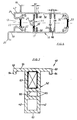
- Fig. 7
- a cross section through an abutment bar for a frame spar.
In Fig.1 ist schematisch ein Türflügel dargestellt, dessen
Türblatt 36 auf halber Höhe oberhalb des Türklinkenbeschlags
43 weggebrochen dargestellt ist, so daß man den Türflügelrahmen
erkennen kann. Dieser besteht aus vier rechtwinklig
zueinander angeordneten Rahmenhohlprofilen 10, von
denen je zwei mit ihren Enden 10' über einen Verbinder 12 gekoppelt
sind. Jedes Rahmenhohlprofil 10 hat zwei abgelängte
Enden 10' und dementsprechend zwei Stoßstellen 11. Die Verbinder
12 haben ihrerseits an den Stoßstellen 11 der Rahmenhohlprofile
10 anliegende Stoßflächen 15, deren Außenumriß
ebenso profiliert ist, wie der Außenumriß der Rahmenhohlprofile
10.In Fig.1 a door leaf is shown schematically, the
Gemäß den Fig.2 bis 4 sind die Rahmenhohlprofile 10 in
derselben Rahmenebene angeordnet und schließen zwischen sich
eine Rahmenfüllung 14 ein, die den Bedürfnissen entsprechend
unterschiedlich ausgebildet sein kann. Die Seitenwände 17 der
Rahmenhohlprofile 10 einer Rahmenseite liegen jeweils in derselben
Ebene, so daß außen auf den Rahmenhohlprofilen 10 Verkleidungsplatten
21 angebracht werden können, und zwar sowohl
flügelinnenseitig, wie auch flügelaußenseitig.According to Figures 2 to 4, the frame
Jedes Rahmenhohlprofil 10 besteht gemäß Fig.6 aus zwei
Halbschalen, welche im wesentlichen die Seitenwände 17 bilden
und miteinander durch Bauteile 33 zusammengehalten sind. Diese
Bauteile 33 sind längsdurchlaufende Leisten aus schlecht
wärmeleitendem Werkstoff, so daß sich auf der einen Seite eines
Rahmenhohlprofils 10 etwa vorhandene Temperaturverhältnisse
nicht durch Wärmeleitung auf die ihr gegenüberliegende,
beispielsweise flügelinnenseitig liegende Halbschale auswirken
können. Eine derartige Ausgestaltung und der Einsatz
schlecht wärmeleitender Bauteile 33 kann sich aber auch erübrigen,
wenn die Rahmenhohlprofile 10 bzw. der Flügel sonst
hinreichend isoliert bzw. wärmedämmend abgedeckt sind.According to FIG. 6, each frame
Damit die Rahmenhohlprofile 10 und die Verbinder 12 zusammengebaut
werden können, sind zwei Einschraubleisten 29
vorhanden, die einander parallel längs durchlaufen und von
einem die beiden Seitenwände 17 miteinander verbindenden und
versteifenden Mittelsteg 44 gehalten werden. Zwischen diese
Einschraubleisten 29 können Befestigungsschrauben mit ihrem
Gewindeteil eingreifen.So that the frame
Die Rahmenhohlprofile 10 haben blendrahmenseitig, also
an ihrer falzseitigen Rahmenfläche 24, eine längsdurchlaufende
Nut 13 als funktionelle Profilierung. Diese Nut 13 dient
beispielsweise der Anordnung eines Treibstangenbeschlags zur
Betätigung von Schließbolzen u.dgl. Im Bereich der Nut 13
können auch weitere Verschlußelemente eingesetzt werden, die
den Flügelrahmen mit dem Blendrahmen bedarfsweise kuppeln
sollen. In Fig.3 ist beispielsweise ein Schloßkasten 45 gestrichelt
dargestellt, dessen Schloß mit seiner Schloßfalle
als Verschlußelement 18 in eine Widerlagerleiste 40 eines
vertikalen Blendrahmenholms 39 eingreift. Der Schloßkasten 45
ist innerhalb eines Rahmenhohlprofils 10 gegen seitliche Bewegungen
in Richtung auf die Seitenwände 17 abgestützt. Hierzu
dienen Distanzhalteleisten 59, die jeweils von einer Innenfläche
58 einer Seitenwand 17 in den Innenraum des Rahmenhohlprofils
10 vorspringen, wobei sie so lang bemessen sind,
daß sie etwa an der Außenwand des Schloßkastens 45 anliegen.
Im Bereich des Schloßkastens 45 wird der Mittelsteg 44 an der
Einbaustelle des Schloßkastens 45 entsprechend entfernt, z.B.
durch Ausfräsen, so daß die am Mittelsteg 44 vorhandenen Einschraubleisten
29, die in Fig.3 noch dargestellt sind, entfallen.
In diesem Bereich wird der Mittelsteg 44 zu zwei Distanzhalteleisten
59. Die dem Schloßkasten 45 benachbarten
inneren eines Paares von Klemmleisten 32 können den Schloßkasten
45 ebenfalls abstützen, wenn die Schloßkastenbreite dem
Abstand zweier einander benachbarter Klemmleisten 32 einander
gegenüberliegender Seitenwände 17 entsprechend bemessen ist.The hollow frame profiles 10 have a frame, so
on its fold-
Den Distanzhalteleisten 59 sind Parallelleisten 60 parallel
angeordnet, und zwar in einem Abstand 61, der das Einschrauben
von Befestigungsmitteln erlaubt. Derartige Befestigungsmittel
sind beispielsweise Schrauben. Mit den Schrauben
können Aufschraubbänder festgelegt werden, die beispielsweise
als Halteplatten für einen Flügelrahmen ausgebildet sind. Das
Rahmenhohlprofil 10 kann bei Einsatz mehrerer Distanzhalteleisten
59 und Parallelleisten 60 so ausgebildet werden, daß
unterschiedliche Abstände erreicht werden, beispielsweise zusätzlich
auch der Abstand 61' im Bereich des Mittelstegs 44.The
Dem Schloßkasten 45 gegenüber zeigt Fig.3 einen feststehenden,
in der Widerlagerleiste 40 befestigten Eingriffsbolzen
46, der in die Nut 13 hineinragt. Wenn die Mündung der
Nut 13 in an sich bekannter Weise mit einem Stulp versehen
ist, in der eine der Vertikalposition des Eingriffsbolzens 46
entsprechende Eingriffsbohrung vorhanden ist, so kann auf
diese Weise eine Sicherung des Türflügels gegen vertikales
Aushebeln erreicht werden, wobei der Eingriffsbolzen 46 so
ausgebildet ist, daß er das Aufschwenken des Türflügels nicht
behindert.3 shows a fixed, opposite the
Die Rahmenprofile 10 weisen von ihren Seitenwänden 17
aus quer vorstehende Befestigungsleisten 19,20 auf. Die Befestigungsleiste
19 steht in Bezug auf die falzseitige Rahmenfläche
24 zurück. Die Befestigungsleiste 20 steht in Bezug
auf die falzseitige Rahmenfläche 24 vor. Infolgedessen bildet
die Seitenwand 17 falzseitig bzw. blendrahmenüberschlagseitig
eine Dichtungsfläche 47, siehe Fig.6, an der gemäß den Fig.2
bis 4 eine Dichtung 48 mit einer Dichtungslippe anliegt, wobei
die Dichtung 48 in einer längsdurchlaufenden Nut 49 des
Blendrahmens festgelegt ist.The frame profiles 10 point from their
Die Befestigungsleiste 20 steht infolge einer Verlängerung
50 der Seitenwand 17 soweit vor, daß ein Überschlag 51
gebildet wird, mit der der Falzraum 52 flügelinnenseitig abgedeckt
wird.The mounting
Die Befestigungsleisten 19,20 laufen über die Länge der
Rahmenhohlprofile durch und können der Aufnahme von Verkleidungsteilen
dienen. Die Fig.2 bis 4 zeigen flügelinnen- und
-außenseitig angeordnete Verkleidungsplatten 21 zwischen zwei
einander gegenüberliegenden Befestigungsleisten 19 außen bzw.
20 innen. Die Verkleidungsplatten 21 überspannen die gesamte
Breite und Höhe des Flügelrahmens, einschließlich der Rahmenfüllung
14. The mounting strips 19,20 run the length of the
Hollow frame profiles through and can accommodate cladding parts
to serve. The Fig.2 to 4 show inside and wing
-covering 21 arranged on the outside between two
opposite mounting strips 19 outside or
20 inside. The
Die Verkleidungsplatten 21 sind so ausgebildet, daß mit
ihnen das Erscheinungsbild des gesamten Tür- oder Fensterflügelrahmens
bzw. -flügels beeinflußt werden kann. Dabei sind
die Befestigungsleisten 19 hinter den Überschlägen 53 der
Blendrahmenholme 39 angeordnet, so daß die rahmenaußenseitige
Sichtfläche 22 ausschließlich die äußere Ansicht des Flügels
bestimmt. Die Sichtfläche 22 der flügelinnenseitigen Verkleidungsplatte
21 ist an ihren Kanten von den Befestigungsleisten
20 ebenso gefaßt, wie die flügelaußenseitige Verkleidungsplatte
21. Die Befestigungsleisten 19,20 sind dabei jeweils
etwa L-förmig ausgebildet, wobei der kurze L-Schenkel
mit der Sichtfläche 22 bündig liegt. Das ist aber nur flügelinnenseitig
sichtbar und könnte auch vermieden werden, falls
gewünscht, indem die Befestigungsleisten 20 in die Kanten der
Verkleidungsplatte 21 eingelassen werden.The
Eine weitere Möglichkeit zur Einflußnahme auf die Ansicht
der flügelinnenseitigen Flügelrahmenfläche besteht darin,
diese mit einer Sichtschalung 23 zu versehen, was in
Fig.4 dargestellt ist. Diese Sichtschalung 23 bekleidet die
Verkleidungsplatte 21 und deren Außenkanten, wobei die Befestigungsleisten
19,20 in Ausnehmungen 54 eingesetzt werden
können und wobei die Verkleidungsplatte 21 ebenso verschraubungsfrei
gehalten werden kann, wie flügelaußenseitig bzw. in
allen Fällen der Fig.2,3.Another way to influence the view
the wing frame surface on the inside of the wing consists of
to provide this with a
Um einen Türflügel bzw. einen Türflügelrahmen an einem
Blendrahmenholm 39 zu befestigen, können Angeln 38 eingesetzt
werden, die mit ihrem als Schraubzapfen ausgebildeten Angelzapfen
35 durch die Befestigungsleiste 20 bzw. deren Sichtschalung
23 hindurch in die Verkleidungsplatte 21 eingebaut
werden. Hierzu kann die Verkleidungsplatte bzw. die Befestigungsleiste
20 im Bereich der Verkleidungsplatte 21 mit einem
Widerlager 37 zur Erhöhung der Einschraubsicherheit des Angelzapfens
35 versehen sein, was in Fig.4 angedeutet wurde.Around a door leaf or a door leaf frame on one
To fasten
Der andere Angelzapfen 41 der Angel 38 ist ebenfalls als
Schraubzapfen ausgebildet und in eine Widerlagerleiste 40
eingeschraubt, die vom Falzraum 52 her in den Blendrahmenholm
39 eingesetzt und daran befestigt ist, z.B. durch Verschraubung.
Die Widerlagerleiste 40 ist als Hohlkammerprofil ausgebildet
und ihr Widerlagerschenkel 62 besitzt zwei Wände 42,
die einander mit Abstand parallel sind. Die Wände 42 sind
blendrahmeninnenseitig miteinander durch einen durchlaufenden
Steg 63 verbunden, während falzraumseitig ein Abdeckschenkel
55 vorhanden ist, der den wesentlichen Bereich der falzraumseitigen
Rahmenfläche einnimmt und auf diese Weise der Einbruchsicherheit
dient. Die T-förmige Gestaltung der Widerlagerleiste
40 bedeutet eine erhebliche Steigerung der Formfestigkeit
des Blendrahmenholms 39. Hierzu ist die Widerlagerleiste
40 auch im übrigen besonders ausgestaltet. Der Abdeckschenkel
55 hat an seinen Enden 63 dem Widerlagerschenkel 62
parallele Rahmeneingriffsleisten 64, die vom Falzraum 52 her
in den Werkstoff des Blendrahmenholms 53 eingreifen und so
dafür sorgen, daß der Abdeckschenkel 55 nicht quer zu diesen
Rahmeneingriffsleisten 64 verschoben werden kann. Zusammen
mit dem Widerlagerschenkel 32 ergibt sich eine verbesserte
Festlegung der gesamten Widerlagerleiste 40. Der Hohlkammerquerschnitt
der Widerlagerleiste 40 bzw. des Widerlagerschenkels
62 wird dadurch erheblich versteift, daß innerhalb des
Widerlagerschenkels 62 einander parallele Querstege 65 vorhanden
sind. Die Querstege 65 erfüllen über ihre Versteifungsfunktion
hinaus eine weitere Funktion, indem sie in einem
Abstand angeordnet sind, der das Einschrauben von Befestigungsmitteln
erlaubt. Solche Befestigungsmittel sind beispielsweise
die Angelzapfen 41 von Angeln 38 zur Halterung
eines Tür- oder Fensterrahmenflügels. Ein Angelzapfen 41 wird
dann quer durch die beiden Wände 42 zwischen den Querstegen
65 hindurchgeschraubt. Letztere haben auf ihren einander zugekehrten
Flächen längsdurchlaufende Gewindehalterippen 66,
ebenso wie die in Fig.6 dargestellten Distanzhalteleisten 59
und die diesen zugeordneten Parallelleisten 60.The
Das Hohlkammerprofil der Widerlagerleiste 40 gestattet
es, die Bewehrung eines Blendrahmens bzw. dessen Widerlagerleisten
40 im Rahmeneckbereich miteinander zu kuppeln. Hierzu
werden Eckwinkel 67 eingesetzt, deren Schenkel jeweils stirnseitig
in den Innenraum der Widerlagerleisten 40 eingreifen,
die einander in dem Rahmeneckbereich benachbart sind und dort
beispielsweise auf Gehrung oder stumpf aneinanderstoßend benachbart
liegen.The hollow chamber profile of the
Der zwischen den Verkleidungsplatten 21 bzw. den Rahmenhohlprofilen
10 gebildete Raum ist mit der Rahmenfüllung 14
versehen, die den technischen Anforderungen entsprechend ausgebildet
sein kann. Die Rahmenfüllung kann, wie das beispielsweise
in Fig.2 angedeutet ist, aus einer inhomogenen
Struktur bestehen. Stattdessen können aber auch gesperrte
Holzleisten oder Wabenstrukturen eingesetzt werden. Auch eine
Isolierglasscheibe kann zum Einsatz kommen, wenn die Verkleidungsplatte
21 einen entsprechenden Ausschnitt freiläßt, im
wesentlichen also lediglich im Bereich der Rahmenhohlprofile
10 vorhanden ist.The between the
In Fig.3,4 ist dargestellt, daß sowohl die Rahmenfüllung 14, als auch der Innenraum der Rahmenhohlprofile 10 in gewünschter Weise ausgefüllt sein kann, beispielsweise mit wärme- und/oder schalldämmendem Werkstoff. Es ist auch möglich, die Durchschußsicherheit dadurch zu erhöhen, daß härteres Material eingesetzt wird, z.B. Flüssigstein.In Fig. 3,4 it is shown that both the frame filling 14, as well as the interior of the hollow frame profiles 10 in the desired Can be filled in, for example with heat and / or soundproofing material. It is also possible, to increase bullet resistance by using harder material is used, e.g. Liquid stone.
Insgesamt ergibt sich durch die Ausgestaltung der Rahmenhohlprofile 10 eine breite Palette von Möglichkeiten, eine Tür bzw. einen Türflügel oder auch einen Fensterflügel so zu gestalten, daß er einerseits den technischen Anforderungen, andererseits den optischen Anforderungen und außerdem noch den Anforderungen an die Einbruchsicherheit gerecht werden kann.Overall, the design of the hollow frame profiles results 10 a wide range of options, one Door or a door wing or a window wing too design that he on the one hand the technical requirements, on the other hand the optical requirements and moreover meet the burglar security requirements can.
Um die vorbeschriebenen Rahmenhohlprofile 10 in geeigneter
Weise miteinander zu verbinden, wird beispielsweise der
in den Fig.5a bis 5d dargestellter Verbinder 12 eingesetzt.
Dieser ist ein im wesentlichen prismatisches bzw. quaderförmiges
Bauteil mit zwei Stoßflächen 15, deren Außenumriß mit
dem Außenumriß der Rahmenhohlprofile 10 identisch ist. Das
ist insbesondere durch Vergleich der Fig.5d mit Fig.6 ersichtlich.
Insbesondere fluchten bei einem eingebauten Verbinder
12 die Seitenflächen 16 mit den Seitenwänden 17 eines
Rahmenhohlprofils 10. To the previously described frame
Da das Rahmenhohlprofil 10 gemäß Fig.6 mehrere funktionelle
Profilierungen aufweist, ist der Verbinder 12 entsprechend
angepaßt. Das gilt zum einen bezüglich der Nut 13, welche
mit gleichem bzw. ähnlichem Profil auch in die falzseitigen
Stirnflächen 54 des Verbinders 12 eingearbeitet ist, also
in diejenigen Stirnseiten, an denen Rahmenhohlprofile 10
nicht anliegen. Es ist infolgedessen möglich, in diesen Nuten
13 des Verbinders 12 Treibstangenbeschläge anzuordnen, beispielsweise
mit einer Eckumlenkung, so daß der Flügelrahmen
mit herkömmlichen Beschlagmitteln bedient werden kann, beispielsweise
mit einem Einhandbeschlag in einer Ausbildung für
Fensterflügel. Spezielle Eck- oder Mittelverriegelungen von
Flügelrahmen sind daher mit nur geringem technischen Aufwand
möglich und können die Einbruchsicherheit des Flügelrahmens
weiter steigern.Since the frame
Eine weitere funktionelle Profilierung des Rahmenhohlprofils
10 besteht in den Befestigungsleisten 19,20. Entsprechende
Befestigungsleisten 19,20 sind gemäß Fig.5d auch am
Verbinder 12 vorhanden, wobei die Befestigungsleisten 19,20
des Verbinders 12 mit denen der Rahmenhohlprofile 10 fluchten.Another functional profiling of the
Der Verbinder 12 ist derart strukturiert, daß er eine
Rahmenstruktur aufweist, mittig also massefreie Bereiche hat.
Dies wird durch eine Gitterstruktur mit Gitterstegen 30 erreicht,
welche jeweils zwei einander gegenüberliegende Rahmenwände
miteinander verbinden und senkrecht zu denjenigen
Gitterstegen 30 stehen, welche die anderen einander gegenüberliegenden
Rahmenwände miteinander verbinden. Gemäß den
Fig.5a,5c sind insgesamt vier Gitterstege 30 vorhanden, die
miteinander und mit dem Rahmen des Verbinders 12 eine einstückige
Struktur bilden.The
Zur Befestigung der Verbinder 12 mit den Rahmenprofilen
10 dienen Befestigungsschrauben 27, die durch Rahmenbohrungen
57 hindurch in die einander parallelen Einschraubleisten 29
eingeschraubt werden, bis der Schraubenkopf die in Fig.5c angedeutete
Stellung einnimmt und dabei die Stoßfläche 15 gegen
die Stoßstelle 11 des Rahmenhohlprofils 10 zieht. Die Befestigungsschraube
27 ist beispielsweise eine Zylinderkopfschraube
mit Innenmehrkant, deren Kopf 28 so dimensioniert
ist, daß die Schraube 27 durch die Ausnehmungen 26 hindurch
bis in die dargestellte Stellung gelangen kann. Mit einem Innenmehrkantschlüssel
ist eine Schraubverstellung der Befestigungsschraube
27 auch dann möglich, wenn diese bei Beginn ihres
Eingriffs in die Einschraubleisten 29 beispielsweise noch
im mittleren Hohlraum 34 des Verbinders 12 angeordnet sein
sollte.For fastening the
Mit einer derartigen Schraubbefestigung ist der Zusammenbau
eines Flügelrahmens mit von den L-förmigen Befestigungsleisten
19,20 umgriffenen Verkleidungsplatten 21 ohne
weiteres möglich, weil diese Verkleidungsplatten problemlos
auf den Seitenflächen von vier Rahmenhohlprofilen 10 angeordnet
werden können, wonach die Verbinder 12 durch nacheinander
erfolgendes Einschrauben der Befestigungsschrauben 27 in ihre
Endmontagestellungen zwischen die Verkleidungsplatten 21 gezogen
werden. Dabei sind die Verbinder 12 relativ zu den Rahmenhohlprofilen
geführt, weil die Verbinder 12 Zentrierzapfen
31 aufweisen, die bereits vor dem Einschrauben der Befestigungsschrauben
27 jeweils zwischen zwei einander parallele
Klemmleisten 32 des zugehörigen Endes 10' des benachbarten
Rahmenprofils 10 eingreifen. Die Klemmleisten 32 sind gemäß
Fig.6 in allen vier Ecken des Profilquerschnitts vorhanden
und gewährleisten eine einwandfreie Lageanordnung des Verbinders
12 auch beim Montieren. Darüber hinaus dienen die Zentrierzapfen
31 als Mittel zur Steigerung der Torsionsfestigkeit
des Flügelrahmens im Bereich der Stoßstellen 11 und entlasten
dementsprechend die Befestigungsschrauben 27.With such a screw attachment is the assembly
a sash with the L-shaped mounting strips
19.20 encompassed
Ein Rahmenhohlprofile kuppelnder Verbinder 12 kann auch
für mehr als zwei Rahmenhohlprofile ausgebildet werden, indem
alle vier schmalen Stirnflächen als Stoßflächen 15 ausgebildet
werden. Ein solcher Verbinder kann beispielsweise vier im
Kreuz zueinander angeordnete Rahmenhohlprofile miteinander
verbinden, was für größere Flügelrahmenkonstruktionen von Bedeutung
ist. In diesem Fall wird eine andere Befestigungstechnik
eingesetzt.A frame hollow
Claims (11)
- Reinforcement on doors or windows having a window/door frame which is to be disposed in a fixed manner and has a counter bearing strip (40) which lies with a cover limb (55) on a rebate-side window/door frame surface, from which cover limb a counter bearing limb (62) engages so as to extend vertically and longitudinally into the window/door frame, wherein a hinge-spigot (41) of the hinge (38) of a wing is screwed into the counter bearing limb (62), characterised in that the counter bearing limb (62) is formed by a hollow chamber profile.
- Reinforcement according to claim 1, characterised in that in cross-section the counter bearing limb (62) protrudes centrally from the cover limb (55) which comprises on its edges (63) parallel frame engagement strips (64) which are shorter than the counter bearing limb (62).
- Reinforcement according to claim 1 or 2, characterised in that inside the counter bearing limb (62) mutually parallel transverse pieces (65) are disposed spaced apart from each other so as to allow attachment means to be screwed in.
- Reinforcement according to any one or several of the claims 1 to 3, characterised in that the counter bearing strips (40) of two angular window/door frame spars are coupled together by corner angles.
- Reinforcement according to any one or several of the claims 1 to 4, characterised in that the spacer strips (59) and their parallel strips (60) of a frame hollow profile (10) of a wing of the door or of the window and/or the transverse pieces (65) of the counter bearing limb (62) comprise longitudinally extending threaded retaining ribs (66) on their mutually facing surfaces.
- Reinforcement according to any one or several of the claims 1 to 5, characterised in that attachment screws of screw-on strips are screwed in between a spacer strip (59) and its parallel strip (60), and/or that hinge-spigots (41) are screwed in a transverse manner through two walls (42) of the hollow chamber profile of the counter bearing strip (40).
- Reinforcement according to any one or several of the claims 1 to 6, characterised in that a frame hollow profile (10) of the wing is allocated in a parallel manner to the said reinforcement and comprises a groove (13) which is open on the rebate-side and into which elements, which comprise engagement bores, or closure elements (18), which are effective on the window/door frame side, are fixedly screwed.
- Reinforcement according to any one or several of the claims 1 to 7, characterised in that the frame hollow profile (10) comprises at least one spacer strip (59), which protrudes from each inner surface (58) of a lateral wall (17), for a lock case (45) whose lock catch bolt and/or lock bolt engage(s) into the counter bearing limb (62).
- Reinforcement according to any one or several of the claims 1 to 8, characterised in that the frame hollow profiles (10), its [sic] connectors (12) and the counter bearing strip (40) consist of metal.
- Reinforcement according to any one or several of the claims 1 to 9, characterised in that the frame profile (10) comprises outwardly protruding attachment strips (19, 20) for fittings or for panelling parts, wherein according to requirement the attachment strips (19, 20) of a lateral wall (17) protrude beyond the rebate-side frame surface (24) in such a manner as to form a frame cover.
- Reinforcement according to any one or several of the claims 1 to 10, characterised in that wing-side hinge-spigots (35) are screwed into a counter bearing (37), which is held by an attachment strip (20), and/or are screwed into a panelling plate (21) held by this strip.
Applications Claiming Priority (2)
| Application Number | Priority Date | Filing Date | Title |
|---|---|---|---|
| DE19500226 | 1995-01-05 | ||
| DE19500226A DE19500226C2 (en) | 1995-01-05 | 1995-01-05 | Door or casement |
Publications (2)
| Publication Number | Publication Date |
|---|---|
| EP0725202A1 EP0725202A1 (en) | 1996-08-07 |
| EP0725202B1 true EP0725202B1 (en) | 1999-07-28 |
Family
ID=7751048
Family Applications (2)
| Application Number | Title | Priority Date | Filing Date |
|---|---|---|---|
| EP95120729A Expired - Lifetime EP0725203B1 (en) | 1995-01-05 | 1995-12-30 | Reinforcement of doors, windows or facades |
| EP95120728A Expired - Lifetime EP0725202B1 (en) | 1995-01-05 | 1995-12-30 | Reinforcement for doors or windows |
Family Applications Before (1)
| Application Number | Title | Priority Date | Filing Date |
|---|---|---|---|
| EP95120729A Expired - Lifetime EP0725203B1 (en) | 1995-01-05 | 1995-12-30 | Reinforcement of doors, windows or facades |
Country Status (3)
| Country | Link |
|---|---|
| EP (2) | EP0725203B1 (en) |
| AT (2) | ATE182652T1 (en) |
| DE (3) | DE19500226C2 (en) |
Families Citing this family (6)
| Publication number | Priority date | Publication date | Assignee | Title |
|---|---|---|---|---|
| DE19739408C1 (en) * | 1997-09-09 | 1999-06-02 | Pax Gmbh | Process for the production of a filling plate which is fitted in a surrounding frame made of profiled bars |
| DE19927719A1 (en) * | 1999-06-17 | 2000-12-21 | Peter Willrich | Draught excluder for insertion between frame and window or door comprises first section attached to frame and second section attached to window or door, first section being deformable and adjusted after installation to produce seal |
| DE19962364C2 (en) * | 1999-12-23 | 2003-10-23 | W & S Vario Schicht Systeme Gm | component |
| DE102005002308B4 (en) * | 2005-01-17 | 2012-06-06 | Adams-Fensterbau Gmbh | front door |
| DE102017217360A1 (en) * | 2017-09-29 | 2019-04-04 | Siemens Mobility GmbH | Custom vehicle door leaf e.g. for a rail vehicle |
| PL233482B1 (en) * | 2017-10-30 | 2019-10-31 | Januszewski Bartosz Zakl Produkcyjny Anbo Spolka Cywilna | Interior doors |
Family Cites Families (7)
| Publication number | Priority date | Publication date | Assignee | Title |
|---|---|---|---|---|
| DE8019955U1 (en) * | 1980-10-16 | Kemmlit-Bauelemente Gmbh, 7400 Tuebingen | Element for walls and / or doors | |
| US2862257A (en) * | 1956-10-26 | 1958-12-02 | John A Comer | Hollow core panel |
| EP0074623B1 (en) * | 1981-09-15 | 1985-12-27 | Wolfgang Zwick | Manufacturing method for door leaves |
| DE8436580U1 (en) * | 1984-12-14 | 1985-04-11 | Brümmer, Roland, 7108 Möckmühl | DO-IT-YOURSELF - WINDOW |
| DE3618482A1 (en) * | 1985-06-18 | 1986-12-18 | Knierim GmbH u. Co KG Metall- und Kunststoffverarbeitung, 3500 Kassel | Corner element for wall or door elements which are intended, in particular, for producing sanitary unitised units |
| DE4308944C3 (en) * | 1993-03-19 | 2002-01-24 | Helmut Siegel | Insect protection device |
| DE4319945A1 (en) * | 1993-06-16 | 1994-12-22 | Hans Dieter Niemann | Wooden door or window frames |
-
1995
- 1995-01-05 DE DE19500226A patent/DE19500226C2/en not_active Expired - Fee Related
- 1995-12-30 EP EP95120729A patent/EP0725203B1/en not_active Expired - Lifetime
- 1995-12-30 AT AT95120728T patent/ATE182652T1/en not_active IP Right Cessation
- 1995-12-30 DE DE59506469T patent/DE59506469D1/en not_active Expired - Fee Related
- 1995-12-30 EP EP95120728A patent/EP0725202B1/en not_active Expired - Lifetime
- 1995-12-30 AT AT95120729T patent/ATE183809T1/en not_active IP Right Cessation
- 1995-12-30 DE DE59506690T patent/DE59506690D1/en not_active Expired - Fee Related
Also Published As
| Publication number | Publication date |
|---|---|
| DE19500226C2 (en) | 1997-12-18 |
| EP0725203B1 (en) | 1999-08-25 |
| ATE183809T1 (en) | 1999-09-15 |
| ATE182652T1 (en) | 1999-08-15 |
| EP0725202A1 (en) | 1996-08-07 |
| DE59506690D1 (en) | 1999-09-30 |
| EP0725203A1 (en) | 1996-08-07 |
| DE19500226A1 (en) | 1996-07-18 |
| DE59506469D1 (en) | 1999-09-02 |
Similar Documents
| Publication | Publication Date | Title |
|---|---|---|
| DE102009012438B4 (en) | pinheader | |
| CH624729A5 (en) | ||
| EP0275235A2 (en) | Door or window with a movable, lockable wing | |
| EP0725202B1 (en) | Reinforcement for doors or windows | |
| AT501873A1 (en) | PROFILE AND METHOD FOR THE PRODUCTION THEREOF | |
| DE4338181C1 (en) | Plastic hollow profile | |
| EP0844348B1 (en) | Hinge for doors or windows | |
| EP0792992B1 (en) | Retrofit door frame | |
| DE19744832C2 (en) | Arrangement for the installation of a window frame | |
| EP2022903B1 (en) | Fixing device and mounting method for installing a support plate into a passage opening between walls | |
| EP1864000B1 (en) | Leaf of a door or a window and method for production of a leaf of a door or a window | |
| EP0128372B1 (en) | Device for fastening one wing of a pair of windows, doors or the like | |
| EP2339095B1 (en) | Door, in particular plastic door, with a lock guard | |
| EP0005283B1 (en) | Fixed metal frame for horizontally movable sliding windows or sliding doors | |
| CH672000A5 (en) | ||
| EP2060726B1 (en) | Hollow profile | |
| DE102006062161A1 (en) | Window or door with a frame profile system comprises a frame made from plastic frame profiles with a mounting groove in the folding region | |
| DE10251431A1 (en) | Door for installation in door aperture in house has hinges connecting moving frame to fixed frame, with frame elements made of hollow profiles | |
| EP3674568B1 (en) | Fitting for a partition wall system, especially for glass partitions | |
| DE3045813A1 (en) | Composite plastics and metal, hollow window frame sections - have support fittings with fasteners locking onto sections and made of complementary material | |
| EP3656955B1 (en) | Striker | |
| EP1970513A2 (en) | Semi-fixed wing of a double door and a lock for the semi-fixed wing | |
| DE8426131U1 (en) | PROFILE FRAME FOR A WINDOW, A DOOR OR. DGL. WITH A GEARBOX HANDLE OD. DGL. | |
| DE3616670A1 (en) | Set of structural elements for a fence | |
| DE2718651A1 (en) | Building window or door frame - uses inner and outer profiles with plastic sheathed hollow aluminium reinforcing inlays |
Legal Events
| Date | Code | Title | Description |
|---|---|---|---|
| PUAI | Public reference made under article 153(3) epc to a published international application that has entered the european phase |
Free format text: ORIGINAL CODE: 0009012 |
|
| AK | Designated contracting states |
Kind code of ref document: A1 Designated state(s): AT BE CH DE FR GB LI NL |
|
| 17P | Request for examination filed |
Effective date: 19961205 |
|
| GRAG | Despatch of communication of intention to grant |
Free format text: ORIGINAL CODE: EPIDOS AGRA |
|
| 17Q | First examination report despatched |
Effective date: 19981112 |
|
| GRAG | Despatch of communication of intention to grant |
Free format text: ORIGINAL CODE: EPIDOS AGRA |
|
| GRAH | Despatch of communication of intention to grant a patent |
Free format text: ORIGINAL CODE: EPIDOS IGRA |
|
| GRAH | Despatch of communication of intention to grant a patent |
Free format text: ORIGINAL CODE: EPIDOS IGRA |
|
| GRAA | (expected) grant |
Free format text: ORIGINAL CODE: 0009210 |
|
| AK | Designated contracting states |
Kind code of ref document: B1 Designated state(s): AT BE CH DE FR GB LI NL |
|
| PG25 | Lapsed in a contracting state [announced via postgrant information from national office to epo] |
Ref country code: NL Free format text: LAPSE BECAUSE OF FAILURE TO SUBMIT A TRANSLATION OF THE DESCRIPTION OR TO PAY THE FEE WITHIN THE PRESCRIBED TIME-LIMIT Effective date: 19990728 Ref country code: GB Free format text: LAPSE BECAUSE OF FAILURE TO SUBMIT A TRANSLATION OF THE DESCRIPTION OR TO PAY THE FEE WITHIN THE PRESCRIBED TIME-LIMIT Effective date: 19990728 Ref country code: FR Free format text: LAPSE BECAUSE OF FAILURE TO SUBMIT A TRANSLATION OF THE DESCRIPTION OR TO PAY THE FEE WITHIN THE PRESCRIBED TIME-LIMIT Effective date: 19990728 |
|
| REF | Corresponds to: |
Ref document number: 182652 Country of ref document: AT Date of ref document: 19990815 Kind code of ref document: T |
|
| REG | Reference to a national code |
Ref country code: CH Ref legal event code: EP |
|
| REF | Corresponds to: |
Ref document number: 59506469 Country of ref document: DE Date of ref document: 19990902 |
|
| EN | Fr: translation not filed | ||
| PG25 | Lapsed in a contracting state [announced via postgrant information from national office to epo] |
Ref country code: AT Free format text: LAPSE BECAUSE OF NON-PAYMENT OF DUE FEES Effective date: 19991230 |
|
| PG25 | Lapsed in a contracting state [announced via postgrant information from national office to epo] |
Ref country code: LI Free format text: LAPSE BECAUSE OF NON-PAYMENT OF DUE FEES Effective date: 19991231 Ref country code: CH Free format text: LAPSE BECAUSE OF NON-PAYMENT OF DUE FEES Effective date: 19991231 Ref country code: BE Free format text: LAPSE BECAUSE OF NON-PAYMENT OF DUE FEES Effective date: 19991231 |
|
| NLV1 | Nl: lapsed or annulled due to failure to fulfill the requirements of art. 29p and 29m of the patents act | ||
| GBV | Gb: ep patent (uk) treated as always having been void in accordance with gb section 77(7)/1977 [no translation filed] |
Effective date: 19990728 |
|
| PLBE | No opposition filed within time limit |
Free format text: ORIGINAL CODE: 0009261 |
|
| STAA | Information on the status of an ep patent application or granted ep patent |
Free format text: STATUS: NO OPPOSITION FILED WITHIN TIME LIMIT |
|
| BERE | Be: lapsed |
Owner name: NIEMANN HANS-DIETER Effective date: 19991231 |
|
| 26N | No opposition filed | ||
| PGFP | Annual fee paid to national office [announced via postgrant information from national office to epo] |
Ref country code: DE Payment date: 20001130 Year of fee payment: 6 |
|
| PG25 | Lapsed in a contracting state [announced via postgrant information from national office to epo] |
Ref country code: DE Free format text: LAPSE BECAUSE OF NON-PAYMENT OF DUE FEES Effective date: 20020702 |