EP0312264A2 - Übertragungsprotokoll und -vorrichtung für ein Netzwerk mit verteilten Stationen - Google Patents
Übertragungsprotokoll und -vorrichtung für ein Netzwerk mit verteilten Stationen Download PDFInfo
- Publication number
- EP0312264A2 EP0312264A2 EP88309370A EP88309370A EP0312264A2 EP 0312264 A2 EP0312264 A2 EP 0312264A2 EP 88309370 A EP88309370 A EP 88309370A EP 88309370 A EP88309370 A EP 88309370A EP 0312264 A2 EP0312264 A2 EP 0312264A2
- Authority
- EP
- European Patent Office
- Prior art keywords
- line
- message
- bus
- interval
- arrangement
- Prior art date
- Legal status (The legal status is an assumption and is not a legal conclusion. Google has not performed a legal analysis and makes no representation as to the accuracy of the status listed.)
- Granted
Links
- 230000005540 biological transmission Effects 0.000 claims abstract description 30
- 238000012544 monitoring process Methods 0.000 claims 6
- 238000010586 diagram Methods 0.000 description 3
- 230000036772 blood pressure Effects 0.000 description 2
- 238000000034 method Methods 0.000 description 2
- 230000001419 dependent effect Effects 0.000 description 1
- 238000009432 framing Methods 0.000 description 1
Images

Classifications
-
- H—ELECTRICITY
- H04—ELECTRIC COMMUNICATION TECHNIQUE
- H04L—TRANSMISSION OF DIGITAL INFORMATION, e.g. TELEGRAPHIC COMMUNICATION
- H04L12/00—Data switching networks
- H04L12/28—Data switching networks characterised by path configuration, e.g. LAN [Local Area Networks] or WAN [Wide Area Networks]
-
- H—ELECTRICITY
- H04—ELECTRIC COMMUNICATION TECHNIQUE
- H04L—TRANSMISSION OF DIGITAL INFORMATION, e.g. TELEGRAPHIC COMMUNICATION
- H04L12/00—Data switching networks
- H04L12/28—Data switching networks characterised by path configuration, e.g. LAN [Local Area Networks] or WAN [Wide Area Networks]
- H04L12/40—Bus networks
- H04L12/407—Bus networks with decentralised control
- H04L12/413—Bus networks with decentralised control with random access, e.g. carrier-sense multiple-access with collision detection [CSMA-CD]
Definitions
- This invention relates to communication systems in which a number of transmitters share a common transmission channel and, in particular, to a collision-free communications protocol for use by transmitters on a common data bus.
- a system such as the above described hospital system could be configured by connecting each remote sensor over its own dedicated communications line to its own dedicated receiver. But for reasons of complexity, flexibility and cost, it is desirable to configure the system by transmitting all sensor information over a common data line to one receiver. The use of the common line, however, creates the need to insure that only one sensor is transmitting information over the line at any one time; otherwise, data transmissions become intertwined and garbled.
- a common solution to this problem is to employ a central controlling station that polls, or queries, the transmitting stations in some sequential order. This solution presents its own undesirable aspects. First, the polling station is constantly active, regardless of whether a transmitter has data to send. Second, a transmitter with an urgent message cannot begin transmitting even when the line is idle: it must wait its turn to be polled. Third, the arrangement presents a reliability problem. If the polling station fails or is otherwise unable to poll correctly, the entire system is disabled.
- the present invention is directed toward a system which prevents message overlap without polling. Instead, a system of the present invention imposes a requirement on each transmitter to insure that the line is idle before transmitting.
- a situation that must be prevented if message overlap is to be eliminated is the simultaneous commencement of transmission by two transmitters, each of whcih has just ascertained that the line is idle. This situation is resolved in accordance with the principles of the present invention by the use of a protocol to be followed by any transmitter before transmission of a message. Under the protocol, the transmitter first senses the state of the line for a given period of time to determine that it is idle. The line is idle if the detected state is uniquely different from any valid data transmission.
- the transmitter then asserts a predetermined state on the line. At the end of this transmission, the transmitter senses the state of the line for another period of time. If no other transmission is sensed during this period, the transmitter is then free to transmit its message.
- This protocol insures that only one transmitter will gain exclusive control over the line at any one time.
- FIGURE 1 the environment of the present invention is illustrated in block diagram form.
- a number of communications devices shown as device #0, device #1, and device #2, are connected to a common communications line, bus 10.
- the devices are operated asynchronously for communication over the bus 10.
- the two-headed arrow connections between each device and the bus indicate that the devices may be transceivers capable of both transmission over the bus and of listening to, or reading the information which is carried by the bus.
- Devices connected to the bus may be capable of only reading the information which is on the bus, but those devices which intend to transmit data over the bus must also be capable of sensing or reading the state of the bus.
- the bus 10 comprises two transmission lines 11 and 12.
- the bus 10 is operated differentially, and each device is interfaced to the bus by a differential bus transceiver which includes a three-state differential line driver D and a differential-input line receiver R.
- These differential bus transceivers are commercially available from Texas Instrument Inc. of Dallas, Texas as Type SN75176 interface circuits. In a differential bus arrangement, it is the relative polarity of the two transmission lines which indicates the information content of the bus.
- a differential receiver R would sense a "high" signal on a line, which may be interpreted by the device as a "1" or a "mark” bit. If line 12 were at a potential of zero volts and line 11 were at a potential of +5 volts, the difference of the two would have a negative sense (0 minus 5) and the receiver R would sense a "low” line signal, which would be interpreted by the device as a "0" or "space” bit, depending on the chosen convention. In the preferred embodiment the transmission lines 11 and 12 are switched between zero and five volts, and the bus is sensed as being in either a mark state or a space state.
- a receiver R need only be capable of sensing the two binary conditions of the mark state and the space state. If the mark state is a "high" signal as interpreted by the transceiver, then the space state is a "low” signal, or vice-versa.
- the line drivers D in the preferred embodiment of FIGURE 2 are capable of presenting three states to the bus 10: a mark state, a space state, and a high impedance state. The latter high impedance state is presented when the device is not transmitting information over the bus. It is imperative in a system in which a station can transmit without prior approval for only one transmitter at a time to be transmitting data. While a transmission is ongoing, the line drivers of the other devices on the bus must be presenting their high impedance state to the bus.
- the line drivers D are controlled by driver enable lines DE. When a DE line is high, the driver is asserting a differential mark or space state on the bus. When the DE line is low, the high impedance state is presented to the bus.
- devices #0 and #2 are connected as transceivers or transmitters, since the devices are connected to both the driver D and the receiver R of their respective interface circuits.
- Device #1 does not transmit data, as it is only connected to the receiver of its interface circuit.
- the device may control the receiver through a receive enable line RE, or the RE line may be held low to continuously receive data with the acceptance or rejection of received data being performed internal to the device.
- FIGURE 2 shows the bus 10 connected to a central station 20 which is in communication with all of the devices on the bus. Like the devices, the central station 20 communicates over the line by way of its own bus transceiver. The bus is also seen to be terminated by resistors 22 and 24, which establish predetermined states on the lines when the bus is idle.
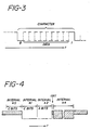
- FIGURE 3 illustrates the serial data format of the characters which are transmitted over the bus in FIGURE 2.
- a data character is ten bits in length, beginning with a space bit 0 and ending with a mark bit 1. Between the mark and space bits are eight bits of data which are variably either mark or space bits.
- a collision-free communication protocol is provided to allow the multiple devices to transmit over the bus without interference with each other. Collision-free communication is desirable because it reduces overhead on the network and it reduces the burden of error control.
- the protocol allows any device wishing to transmit a message a means of gaining exclusive control over the data bus.
- the protocol of the preferred embodiment is shown in FIGURE 4.
- a device To send a message over the bus a device invokes the following procedure. First, the device listens to the bus through its receiver R for a line condition that indicates the absence of character transmission on the bus. This is shown in FIGURE 4 as interval #0, which has a duration of C bits. The determination of the absence of character transmission on the bus is dependent upon the character format. In the example of FIGURE 3, a character is seen to contain a space bit and a mark bit within the character bit length of ten bits. Therefore, if interval #0 is ten bits in length and the device desiring to transmit senses no space bit during this time, the device would conclude that there is no character transmission ongoing; the bus is idle. During interval #0 the device would see the condition established when the high impedance state is presented to the bus by all other devices, as indicated by the shaded bar in FIGURE 4. If the device would sense a space bit on the bus during interval #0, it would restart the interval.
- the terminating resistors 22 and 24 establish the condition of the mark state on the bus during those times that all drivers are presenting their high impedance state to the bus. Under these conditions, and with the character format of FIGURE 3, an idle bus would be determined by C consecutive bits of the mark state where C is equal to ten. In essence, the device is listening for the absence of the initial space bit of a character.
- the receivers R of the preferred embodiment need only be capable of sensing the mark and space states of the bus. It is not necessary for the receiver to sense the existence of the high impedance state presented by all other stations on the line. This lesser requirement allows the use of relatively simple, commercially available transceivers in the preferred embodiment, as discussed above. If a receiver capable of distinguishing between all three bus states were used, a termination establishing a high impedance condition would be employed, and either the mark or space bit of a character transmission would be sensed to indicate that the bus is not idle.
- interval #1 and interval #2 where C bits is the character length and "a" bits is a unique device identifier bit sequence.
- the space state overrides the high impedance condition of the bus, and also the mark state established by the terminating resistors, if present.
- the C bits of the space condition of interval #1 with a bit length of ten in this example, presents what is unambiguously an invalid character when the character format of FIGURE 3 is used. Thus, any receiver listening on the bus for character information would identify the interval #1 transmission as an invalid character by reason of the absence of the tenth mark bit.
- interval #1 is followed by a further interval #2 of "a" bits of the space condition.
- This is an address transmission which identifies the source of the message and also establishes priority among devices competing for bus access.
- the address "a” uniquely identifies a device and has a bit length varying between 0 and minimally N-1, where N is the number of transmitting devices on the bus.
- N is the number of transmitting devices on the bus.
- a bit length "a" equal to zero, one, or two would uniquely identify each of the three devices.
- the driver is switched from the space condition to the high impedance condition, and the state of the bus is sensed. If the bus is sensed as being in the mark state (i.e., all other transmitters are in the high impedance state), then the device has exclusive control of the bus and can begin a continuous transmission of data characters. At the end of the data transmission the driver switches back to the high impedance condition.
- the sensing period after interval #2 is one bit in length. If the sensing period were C bits or longer, it may be appreciated that another device on the bus would identify the period as an idle bus condition during its own interval #0. Accordingly, the sense period must have a duration of less than C bits. A one bit duration is optimal for establishing the shortest protocol length. However, if propagation delay along the bus is a significant consideration, then the sensing period must be set to be greater than the network's propagation delay, which is functionally related to the baud rate of a serial communications system.
- a further advantage of the protocol of the present invention is that receiving devices need no special logic to decode or discriminate the protocol. Many traditional asynchronous receivers will reject C or greater bit lengths of space bits as invalid characters. In the protocol of FIGURE 4, the time during which the protocol is actively asserting the bus, intervals #1 and #2, comprises just such a sequence of space bits. Thus, the asynchronous receivers on the bus will detect the protocol as simply an invalid transmission and will reject it. The reception of valid data does not occur until the first character transmitted at the beginning of interval #4, when a device has acquired exclusive control of the bus.
- the interval #0 may be seen to serve two purposes. On the one hand it is the first procedure in the protocol. On the other, it serves as a message framing interval.
- a receiving device When a message of consecutive characters ends, a receiving device generally will know the message has ended by sensing the ten bits of the mark state which follow the message, when no device is asserting the bus. Thus, the ten bits of mark at the end of a message serve to inform the receiving device that the message has ended; and the mark bits also serve as interval #0 for a device which has been waiting to transmit over the bus.
- the communication system of the present invention has been successfully employed in a network of automated blood pressure monitors connected to a central receiving station.
- the monitors automatically take blood pressure readings and send medical information at intervals ranging from once every several hours to several times a second.
- the monitors asynchronously send data over a common line without interference. Asynchronous operation would also occur if the monitors were not operated automatically, but were activated periodically by a nurse making rounds from patient to patient.
- the protocol of the present invention solves a very real problem in the hospital environment where, after a lengthy transmission by one device, several waiting devices will simultaneously attempt to assume control over the bus. The protocol avoids collisions without any intervention from the central station.
- the present invention is equally applicable to single-ended line systems.
Landscapes
- Engineering & Computer Science (AREA)
- Computer Networks & Wireless Communication (AREA)
- Signal Processing (AREA)
- Small-Scale Networks (AREA)
- Communication Control (AREA)
- Data Exchanges In Wide-Area Networks (AREA)
- Computer And Data Communications (AREA)
- Maintenance And Management Of Digital Transmission (AREA)
Applications Claiming Priority (2)
| Application Number | Priority Date | Filing Date | Title |
|---|---|---|---|
| US106748 | 1987-10-08 | ||
| US07/106,748 US4807223A (en) | 1987-10-08 | 1987-10-08 | Communications protocol for distributed station network |
Publications (3)
| Publication Number | Publication Date |
|---|---|
| EP0312264A2 true EP0312264A2 (de) | 1989-04-19 |
| EP0312264A3 EP0312264A3 (en) | 1990-10-24 |
| EP0312264B1 EP0312264B1 (de) | 1994-06-15 |
Family
ID=22313042
Family Applications (1)
| Application Number | Title | Priority Date | Filing Date |
|---|---|---|---|
| EP88309370A Expired - Lifetime EP0312264B1 (de) | 1987-10-08 | 1988-10-07 | Übertragungsprotokoll und -vorrichtung für ein Netzwerk mit verteilten Stationen |
Country Status (15)
| Country | Link |
|---|---|
| US (1) | US4807223A (de) |
| EP (1) | EP0312264B1 (de) |
| JP (2) | JPH01135241A (de) |
| KR (1) | KR960014977B1 (de) |
| CN (1) | CN1016833B (de) |
| AT (1) | ATE107449T1 (de) |
| AU (1) | AU604980B2 (de) |
| CA (1) | CA1322391C (de) |
| DE (1) | DE3850209T2 (de) |
| ES (1) | ES2056111T3 (de) |
| GR (1) | GR1000361B (de) |
| MX (1) | MX170934B (de) |
| NO (1) | NO884483L (de) |
| PT (1) | PT88702B (de) |
| ZA (1) | ZA887553B (de) |
Families Citing this family (16)
| Publication number | Priority date | Publication date | Assignee | Title |
|---|---|---|---|---|
| JPH0646733B2 (ja) * | 1987-06-30 | 1994-06-15 | 沖電気工業株式会社 | 1つの伝送媒体を共有する競合制御方式 |
| US5200743A (en) * | 1989-09-01 | 1993-04-06 | Bently Nevada | Multiple remote sensor system for real time analog sensing and differential cummunication |
| US5142277A (en) * | 1990-02-01 | 1992-08-25 | Gulton Industries, Inc. | Multiple device control system |
| US5230044A (en) * | 1990-07-02 | 1993-07-20 | Digital Equipment Corporation | Arbitration apparatus for shared bus |
| US5239630A (en) * | 1990-07-02 | 1993-08-24 | Digital Equipment Corporation | Shared bus arbitration apparatus having a deaf node |
| WO1992014210A1 (en) * | 1991-02-07 | 1992-08-20 | Datacard Corporation | Network interface circuit apparatus and method |
| US5661467A (en) * | 1991-02-18 | 1997-08-26 | Nec Corporation | Method and system for transferring supervisory right requirement in submarine cable communication network system |
| EP0524676A1 (de) * | 1991-07-08 | 1993-01-27 | Koninklijke Philips Electronics N.V. | Verfahren und Schaltungsanordnung zur Datenübertragung |
| GB9118040D0 (en) * | 1991-08-21 | 1991-10-09 | D2B Systems Co Ltd | Method of identifying a signal path and signal processing apparatus |
| US5694617A (en) * | 1995-03-31 | 1997-12-02 | International Business Machines Corporation | System for prioritizing quiesce requests and recovering from a quiescent state in a multiprocessing system with a milli-mode operation |
| US5734675A (en) * | 1996-01-16 | 1998-03-31 | Lucent Technologies Inc. | Receiver sharing for demand priority access method repeaters |
| US5729547A (en) * | 1996-02-07 | 1998-03-17 | Dutec, Inc. | Automatic driver/receiver control for half-duplex serial networks |
| US6751232B1 (en) * | 1997-12-22 | 2004-06-15 | Nortel Networks Limited | Method and apparatus for communicating data between first and second pairs of transceivers communicating on a common communications link |
| US6275883B1 (en) * | 1999-01-15 | 2001-08-14 | Advanced Memory International, Inc. | Contention-free signaling scheme for shared control signals |
| US6625163B1 (en) * | 1999-04-21 | 2003-09-23 | Nortel Networks Ltd. | Collision detection on a differential bus |
| CN108270652B (zh) * | 2017-12-29 | 2021-03-30 | 北京纳米维景科技有限公司 | 一种高速实时总线系统及其数据处理方法 |
Family Cites Families (9)
| Publication number | Priority date | Publication date | Assignee | Title |
|---|---|---|---|---|
| US4395710A (en) * | 1980-11-26 | 1983-07-26 | Westinghouse Electric Corp. | Bus access circuit for high speed digital data communication |
| US4345250A (en) * | 1980-12-22 | 1982-08-17 | Honeywell Information Systems Inc. | Information communication system with collision avoidance |
| GB2101457B (en) * | 1981-07-08 | 1985-04-17 | Int Computers Ltd | Data communication system |
| US4476467A (en) * | 1982-06-08 | 1984-10-09 | Cromemco Inc. | Random entry intercomputer network with collision prevention |
| JPS59135965A (ja) * | 1983-01-24 | 1984-08-04 | Nec Corp | 加入者線アクセス方式 |
| JPS59212048A (ja) * | 1983-05-18 | 1984-11-30 | Canon Inc | デ−タ伝送制御方式 |
| US4551721A (en) * | 1983-10-07 | 1985-11-05 | Honeywell Inc. | Method for initializing a token-passing local-area network |
| DE3420232C2 (de) * | 1984-05-30 | 1987-04-23 | Honeywell Regelsysteme GmbH, 6050 Offenbach | Verfahren zur Auswahl von an einen seriellen Bus angeschlossenen Teilnehmern |
| JPS61186045A (ja) * | 1985-02-13 | 1986-08-19 | Meidensha Electric Mfg Co Ltd | ネツトワ−クシステムにおけるアクセス方式 |
-
1987
- 1987-10-08 US US07/106,748 patent/US4807223A/en not_active Expired - Fee Related
-
1988
- 1988-10-06 CA CA000579510A patent/CA1322391C/en not_active Expired - Fee Related
- 1988-10-07 ES ES88309370T patent/ES2056111T3/es not_active Expired - Lifetime
- 1988-10-07 EP EP88309370A patent/EP0312264B1/de not_active Expired - Lifetime
- 1988-10-07 PT PT88702A patent/PT88702B/pt not_active IP Right Cessation
- 1988-10-07 AU AU23573/88A patent/AU604980B2/en not_active Ceased
- 1988-10-07 DE DE3850209T patent/DE3850209T2/de not_active Expired - Fee Related
- 1988-10-07 AT AT88309370T patent/ATE107449T1/de not_active IP Right Cessation
- 1988-10-07 ZA ZA887553A patent/ZA887553B/xx unknown
- 1988-10-07 MX MX013345A patent/MX170934B/es unknown
- 1988-10-07 NO NO88884483A patent/NO884483L/no unknown
- 1988-10-08 KR KR1019880013153A patent/KR960014977B1/ko not_active Expired - Fee Related
- 1988-10-08 CN CN88108427A patent/CN1016833B/zh not_active Expired
- 1988-10-08 JP JP63254669A patent/JPH01135241A/ja active Pending
- 1988-10-10 GR GR880100677A patent/GR1000361B/el unknown
-
1998
- 1998-04-27 JP JP003235U patent/JPH1188U/ja active Pending
Also Published As
| Publication number | Publication date |
|---|---|
| NO884483D0 (no) | 1988-10-07 |
| CA1322391C (en) | 1993-09-21 |
| PT88702B (pt) | 1994-03-31 |
| ZA887553B (en) | 1990-06-27 |
| MX170934B (es) | 1993-09-22 |
| PT88702A (pt) | 1989-07-31 |
| ES2056111T3 (es) | 1994-10-01 |
| KR960014977B1 (ko) | 1996-10-23 |
| JPH01135241A (ja) | 1989-05-26 |
| AU604980B2 (en) | 1991-01-03 |
| EP0312264A3 (en) | 1990-10-24 |
| JPH1188U (ja) | 1999-07-13 |
| ATE107449T1 (de) | 1994-07-15 |
| EP0312264B1 (de) | 1994-06-15 |
| CN1036089A (zh) | 1989-10-04 |
| DE3850209D1 (de) | 1994-07-21 |
| CN1016833B (zh) | 1992-05-27 |
| AU2357388A (en) | 1989-04-13 |
| GR1000361B (el) | 1992-06-30 |
| KR890007528A (ko) | 1989-06-20 |
| NO884483L (no) | 1989-04-10 |
| DE3850209T2 (de) | 1994-09-22 |
| US4807223A (en) | 1989-02-21 |
Similar Documents
| Publication | Publication Date | Title |
|---|---|---|
| US4807223A (en) | Communications protocol for distributed station network | |
| US4988990A (en) | Dual master implied token communication system | |
| US5122794A (en) | Dual master implied token communication system | |
| US5166678A (en) | Dual master implied token communication system | |
| US5515035A (en) | Method and equipment for bidirectional data transmission (protocol) | |
| EP0435037B1 (de) | "Master-Slave" industrielles Netzwerk mit Tokenübergabe | |
| US4434421A (en) | Method for digital data transmission with bit-echoed arbitration | |
| US4516205A (en) | Access control of data transmission network | |
| US5642350A (en) | Peer to peer network for a mobile radio transceiver | |
| US5140586A (en) | Token associated data network communications protocol | |
| EP0539796A2 (de) | Verfahren zur Datakollisionserkennung in einem Multiprozessorenübertragungsnetz | |
| EP0081821A1 (de) | System von lokalen Netzen mit Konkurrenzbetrieb | |
| US5065153A (en) | Contention control system | |
| US4191941A (en) | Switch matrix for data transfers | |
| EP0602827B1 (de) | Digitale Mehrmaster-Übertragungstechnik mit einem eigenen Konkurrenzbus | |
| US20020075885A1 (en) | Multiple device communications | |
| EP0718988B1 (de) | Optisches Datenübertragungssystem und entsprechendes Verfahren | |
| JP3042822B2 (ja) | バス競合制御方式 | |
| WO1990015491A1 (en) | Data communication apparatus | |
| US5732625A (en) | Method and system for transmitting signals in a printing machine | |
| JP2691005B2 (ja) | 通信方式 | |
| JPS622742A (ja) | 衝突検出方式 | |
| JPS62287723A (ja) | 通信監視装置 | |
| GB2122779A (en) | Access control of data transmission network | |
| JPS63294030A (ja) | バス形の網の情報転送方式 |
Legal Events
| Date | Code | Title | Description |
|---|---|---|---|
| PUAI | Public reference made under article 153(3) epc to a published international application that has entered the european phase |
Free format text: ORIGINAL CODE: 0009012 |
|
| AK | Designated contracting states |
Kind code of ref document: A2 Designated state(s): AT BE CH DE ES FR GB IT LI LU NL SE |
|
| RAP1 | Party data changed (applicant data changed or rights of an application transferred) |
Owner name: CRITIKON, INC. (A FLORIDA CORPORATION) |
|
| RAP3 | Party data changed (applicant data changed or rights of an application transferred) |
Owner name: CRITIKON, INC. |
|
| PUAL | Search report despatched |
Free format text: ORIGINAL CODE: 0009013 |
|
| AK | Designated contracting states |
Kind code of ref document: A3 Designated state(s): AT BE CH DE ES FR GB IT LI LU NL SE |
|
| 17P | Request for examination filed |
Effective date: 19901123 |
|
| 17Q | First examination report despatched |
Effective date: 19921125 |
|
| GRAA | (expected) grant |
Free format text: ORIGINAL CODE: 0009210 |
|
| AK | Designated contracting states |
Kind code of ref document: B1 Designated state(s): AT BE CH DE ES FR GB IT LI LU NL SE |
|
| REF | Corresponds to: |
Ref document number: 107449 Country of ref document: AT Date of ref document: 19940715 Kind code of ref document: T |
|
| REF | Corresponds to: |
Ref document number: 3850209 Country of ref document: DE Date of ref document: 19940721 |
|
| ET | Fr: translation filed | ||
| ITF | It: translation for a ep patent filed | ||
| REG | Reference to a national code |
Ref country code: ES Ref legal event code: FG2A Ref document number: 2056111 Country of ref document: ES Kind code of ref document: T3 |
|
| PGFP | Annual fee paid to national office [announced via postgrant information from national office to epo] |
Ref country code: DE Payment date: 19941010 Year of fee payment: 7 |
|
| EAL | Se: european patent in force in sweden |
Ref document number: 88309370.0 |
|
| PLBE | No opposition filed within time limit |
Free format text: ORIGINAL CODE: 0009261 |
|
| STAA | Information on the status of an ep patent application or granted ep patent |
Free format text: STATUS: NO OPPOSITION FILED WITHIN TIME LIMIT |
|
| 26N | No opposition filed | ||
| PG25 | Lapsed in a contracting state [announced via postgrant information from national office to epo] |
Ref country code: DE Effective date: 19960702 |
|
| PGFP | Annual fee paid to national office [announced via postgrant information from national office to epo] |
Ref country code: GB Payment date: 19970929 Year of fee payment: 10 |
|
| PGFP | Annual fee paid to national office [announced via postgrant information from national office to epo] |
Ref country code: FR Payment date: 19971009 Year of fee payment: 10 |
|
| PGFP | Annual fee paid to national office [announced via postgrant information from national office to epo] |
Ref country code: AT Payment date: 19971014 Year of fee payment: 10 |
|
| PGFP | Annual fee paid to national office [announced via postgrant information from national office to epo] |
Ref country code: SE Payment date: 19971015 Year of fee payment: 10 Ref country code: LU Payment date: 19971015 Year of fee payment: 10 |
|
| PGFP | Annual fee paid to national office [announced via postgrant information from national office to epo] |
Ref country code: ES Payment date: 19971017 Year of fee payment: 10 |
|
| PGFP | Annual fee paid to national office [announced via postgrant information from national office to epo] |
Ref country code: CH Payment date: 19971023 Year of fee payment: 10 |
|
| PGFP | Annual fee paid to national office [announced via postgrant information from national office to epo] |
Ref country code: NL Payment date: 19971029 Year of fee payment: 10 |
|
| PGFP | Annual fee paid to national office [announced via postgrant information from national office to epo] |
Ref country code: BE Payment date: 19971211 Year of fee payment: 10 |
|
| PG25 | Lapsed in a contracting state [announced via postgrant information from national office to epo] |
Ref country code: LU Free format text: LAPSE BECAUSE OF NON-PAYMENT OF DUE FEES Effective date: 19981007 Ref country code: GB Free format text: LAPSE BECAUSE OF NON-PAYMENT OF DUE FEES Effective date: 19981007 Ref country code: AT Free format text: LAPSE BECAUSE OF NON-PAYMENT OF DUE FEES Effective date: 19981007 |
|
| PG25 | Lapsed in a contracting state [announced via postgrant information from national office to epo] |
Ref country code: SE Free format text: LAPSE BECAUSE OF NON-PAYMENT OF DUE FEES Effective date: 19981008 Ref country code: ES Free format text: LAPSE BECAUSE OF NON-PAYMENT OF DUE FEES Effective date: 19981008 |
|
| PG25 | Lapsed in a contracting state [announced via postgrant information from national office to epo] |
Ref country code: LI Free format text: LAPSE BECAUSE OF NON-PAYMENT OF DUE FEES Effective date: 19981031 Ref country code: CH Free format text: LAPSE BECAUSE OF NON-PAYMENT OF DUE FEES Effective date: 19981031 Ref country code: BE Free format text: LAPSE BECAUSE OF NON-PAYMENT OF DUE FEES Effective date: 19981031 |
|
| BERE | Be: lapsed |
Owner name: CRITIKON INC. Effective date: 19981031 |
|
| PG25 | Lapsed in a contracting state [announced via postgrant information from national office to epo] |
Ref country code: NL Free format text: LAPSE BECAUSE OF NON-PAYMENT OF DUE FEES Effective date: 19990501 |
|
| GBPC | Gb: european patent ceased through non-payment of renewal fee |
Effective date: 19981007 |
|
| REG | Reference to a national code |
Ref country code: CH Ref legal event code: PL |
|
| EUG | Se: european patent has lapsed |
Ref document number: 88309370.0 |
|
| PG25 | Lapsed in a contracting state [announced via postgrant information from national office to epo] |
Ref country code: FR Free format text: LAPSE BECAUSE OF NON-PAYMENT OF DUE FEES Effective date: 19990630 |
|
| NLV4 | Nl: lapsed or anulled due to non-payment of the annual fee |
Effective date: 19990501 |
|
| REG | Reference to a national code |
Ref country code: FR Ref legal event code: ST |
|
| REG | Reference to a national code |
Ref country code: ES Ref legal event code: FD2A Effective date: 19991113 |
|
| PG25 | Lapsed in a contracting state [announced via postgrant information from national office to epo] |
Ref country code: IT Free format text: LAPSE BECAUSE OF NON-PAYMENT OF DUE FEES;WARNING: LAPSES OF ITALIAN PATENTS WITH EFFECTIVE DATE BEFORE 2007 MAY HAVE OCCURRED AT ANY TIME BEFORE 2007. THE CORRECT EFFECTIVE DATE MAY BE DIFFERENT FROM THE ONE RECORDED. Effective date: 20051007 |