EP0312065B1 - Sicherheitsvorrichtung für einen Wäschetrockner - Google Patents
Sicherheitsvorrichtung für einen Wäschetrockner Download PDFInfo
- Publication number
- EP0312065B1 EP0312065B1 EP88117058A EP88117058A EP0312065B1 EP 0312065 B1 EP0312065 B1 EP 0312065B1 EP 88117058 A EP88117058 A EP 88117058A EP 88117058 A EP88117058 A EP 88117058A EP 0312065 B1 EP0312065 B1 EP 0312065B1
- Authority
- EP
- European Patent Office
- Prior art keywords
- input
- voltage
- circuit
- tension roller
- electric
- Prior art date
- Legal status (The legal status is an assumption and is not a legal conclusion. Google has not performed a legal analysis and makes no representation as to the accuracy of the status listed.)
- Expired - Lifetime
Links
Images


Classifications
-
- D—TEXTILES; PAPER
- D06—TREATMENT OF TEXTILES OR THE LIKE; LAUNDERING; FLEXIBLE MATERIALS NOT OTHERWISE PROVIDED FOR
- D06F—LAUNDERING, DRYING, IRONING, PRESSING OR FOLDING TEXTILE ARTICLES
- D06F58/00—Domestic laundry dryers
- D06F58/02—Domestic laundry dryers having dryer drums rotating about a horizontal axis
- D06F58/04—Details
- D06F58/08—Driving arrangements
-
- D—TEXTILES; PAPER
- D06—TREATMENT OF TEXTILES OR THE LIKE; LAUNDERING; FLEXIBLE MATERIALS NOT OTHERWISE PROVIDED FOR
- D06F—LAUNDERING, DRYING, IRONING, PRESSING OR FOLDING TEXTILE ARTICLES
- D06F2103/00—Parameters monitored or detected for the control of domestic laundry washing machines, washer-dryers or laundry dryers
- D06F2103/02—Characteristics of laundry or load
- D06F2103/04—Quantity, e.g. weight or variation of weight
-
- D—TEXTILES; PAPER
- D06—TREATMENT OF TEXTILES OR THE LIKE; LAUNDERING; FLEXIBLE MATERIALS NOT OTHERWISE PROVIDED FOR
- D06F—LAUNDERING, DRYING, IRONING, PRESSING OR FOLDING TEXTILE ARTICLES
- D06F2103/00—Parameters monitored or detected for the control of domestic laundry washing machines, washer-dryers or laundry dryers
- D06F2103/02—Characteristics of laundry or load
- D06F2103/06—Type or material
-
- D—TEXTILES; PAPER
- D06—TREATMENT OF TEXTILES OR THE LIKE; LAUNDERING; FLEXIBLE MATERIALS NOT OTHERWISE PROVIDED FOR
- D06F—LAUNDERING, DRYING, IRONING, PRESSING OR FOLDING TEXTILE ARTICLES
- D06F2103/00—Parameters monitored or detected for the control of domestic laundry washing machines, washer-dryers or laundry dryers
- D06F2103/24—Spin speed; Drum movements
-
- D—TEXTILES; PAPER
- D06—TREATMENT OF TEXTILES OR THE LIKE; LAUNDERING; FLEXIBLE MATERIALS NOT OTHERWISE PROVIDED FOR
- D06F—LAUNDERING, DRYING, IRONING, PRESSING OR FOLDING TEXTILE ARTICLES
- D06F2103/00—Parameters monitored or detected for the control of domestic laundry washing machines, washer-dryers or laundry dryers
- D06F2103/38—Time, e.g. duration
-
- D—TEXTILES; PAPER
- D06—TREATMENT OF TEXTILES OR THE LIKE; LAUNDERING; FLEXIBLE MATERIALS NOT OTHERWISE PROVIDED FOR
- D06F—LAUNDERING, DRYING, IRONING, PRESSING OR FOLDING TEXTILE ARTICLES
- D06F2103/00—Parameters monitored or detected for the control of domestic laundry washing machines, washer-dryers or laundry dryers
- D06F2103/44—Current or voltage
-
- D—TEXTILES; PAPER
- D06—TREATMENT OF TEXTILES OR THE LIKE; LAUNDERING; FLEXIBLE MATERIALS NOT OTHERWISE PROVIDED FOR
- D06F—LAUNDERING, DRYING, IRONING, PRESSING OR FOLDING TEXTILE ARTICLES
- D06F34/00—Details of control systems for washing machines, washer-dryers or laundry dryers
- D06F34/08—Control circuits or arrangements thereof
-
- D—TEXTILES; PAPER
- D06—TREATMENT OF TEXTILES OR THE LIKE; LAUNDERING; FLEXIBLE MATERIALS NOT OTHERWISE PROVIDED FOR
- D06F—LAUNDERING, DRYING, IRONING, PRESSING OR FOLDING TEXTILE ARTICLES
- D06F37/00—Details specific to washing machines covered by groups D06F21/00 - D06F25/00
- D06F37/42—Safety arrangements, e.g. for stopping rotation of the receptacle upon opening of the casing door
-
- D—TEXTILES; PAPER
- D06—TREATMENT OF TEXTILES OR THE LIKE; LAUNDERING; FLEXIBLE MATERIALS NOT OTHERWISE PROVIDED FOR
- D06F—LAUNDERING, DRYING, IRONING, PRESSING OR FOLDING TEXTILE ARTICLES
- D06F58/00—Domestic laundry dryers
- D06F58/32—Control of operations performed in domestic laundry dryers
- D06F58/34—Control of operations performed in domestic laundry dryers characterised by the purpose or target of the control
- D06F58/50—Responding to irregular working conditions, e.g. malfunctioning of blowers
Definitions
- the invention relates to a laundry dryer and in particular to a safety device for a laundry drier adapted to interrupt the electric power supply to the machine whenever the drum is not properly rotated by the associated electric motor, in the case for instance of rupture or excessive elongation of the transmission belt connected between the drum and the electric motor.
- Known laundry driers substantially comprise a blower and at least one heater element operable to establish a circulation of hot air through a conduit containing a filter for retaining fluff and any possible foreign bodies to the interior of a drum containing the laundry to be dried and adapted to be rotated by an electric motor with the aid of a transmission belt connected between the drum and the electric motor.
- electro-mechanical safety devices For preventing such malfunctions from occurring, electro-mechanical safety devices have already been proposed, such safety devices being operable to interrupt the electric power supply to the machine in response to rupture or excessive elongation of the transmission belt.
- the bracket is resiliently biased by the tension of the transmission belt towards an operative position to thereby keep the breaker switch in the closed state ensuring the continued supply of electric power to the machine.
- the bracket In the case of possible rupture or excessive elongation of the belt, however, the bracket is no longer biased by the tension of the belt and thus permitted to assume an alternative operative position, causing the breaker switch to open and to thereby interupt the power supply to the machine.
- This safety device is employed in a laundry washing machine comprising a tension roller acting on the transmission belt and carried by a spring-biased lever mounted on the base of the machine and acting on a breaker switch incorporated in the electric power supply circuit of the machine.
- these known safety devices are not capable of interrupting the electric power supply to the respective machine in the possible case of damage or malfunction of the belt tensioning mechanism (comprising the elastic bracket or the spring-biased lever, respectively) so that in this case the electric power supply to the machine is continued although the drum might have come to a standstill or might be rotated at a reduced speed.
- a laundry drier having a combination idler and belt failure switch associated to a pulley engaged by a belt by means of which the drum of the drier is driven by a motor.
- An idler pulley is supported and biased by a bracket to maintain tension of the belt.
- linkage means are provided interconnecting the idler pulley and the centrifugal switch for deactuating said switch to cease operation of the motor in response to the breaking of the belt.
- power supply to heater elements is controlled by the same switch, heating is interrupted as well upon deactuation of the switch.
- a control device for a rotational movement of a turning member in an apparatus like a laundry washing-machine comprising electronic means for detecting the rotational speed of the rotating member which may be a pulley to drive a drum.
- the detector is formed by a magnetic coil connected to an electronic circuit, and the coil is influenced by a magnet disposed at the rotating member. If rotational speed of the rotating member does not exceed the predetermined threshhold, heating elements of the washing-machine are switched off or a programme unit is controlled to attain its initial position in which all power to the electric components of the washing-machine is switched off.
- the known arrangements suffer from suitably indicating any condition of disorder of the machine, so that it is the object of the invention to provide a laundry drier permitting to signal automatically the correct or incorrect operation of the drier through suitable control means.
- a lower portion of a laundry drier 7 having a housing 8 surrounding a drum 9 adapted to be rotated by an electric motor 10 of conventional construction mounted on the base 11 of the machine.
- the present laundry drier also comprises a blower 12 connected to a conduit 13 leading to the interior of drum 9 and defined between the walls of housing 8 and the drum 9 itself.
- conduit 13 Mounted within conduit 13 are at least one heater element and a filter of conventional construction (both of which are not shown), adapted respectively to heat the flow of air produced by blower 12, and to retain fluff and any foreign bodies possibly entrained by the air flow.
- Drum 9 of the described machine on its part is adapted to be rotated by electric motor 10, preferably in a single direction, with the aid of a transmission belt 14 extending between a driving pulley 15 associated to motor 10 and a driven pulley formed by or on the circumferential surface of drum 9.
- transmission belt 14 is kept under tension by at least one tension roller 16 of conventional type to thereby ensure the efficient transmission of the driving force from motor 10 to drum 9, said tension roller 16 being mounted in a lower portion of the machine in the manner to be described.
- FIG. 2 With reference now to Figs. 2 and 3, there is shown a first embodiment of a safety device according to the invention.
- tension roller 16 has a centrally mounted extended shaft 17 adapted to extend through the bore (not shown) of a slide bushing 18 and through a corresponding bore (not shown) drilled in a projection 19 of the front shield 20 of motor 10.
- This tension roller 16 is further provided with two lateral stop disks 21 and 22 adapted to prevent any lateral displacement of transmission belt 14 during operation of the machine.
- Tension roller 16 is thus mounted in the bore of projection 19 in a freely rotatable manner and in pressure contact with transmission belt 14 due to the tension of the latter, so as to be rotated by the movement of the belt during operation of the machine.
- the present safety device comprises a set of radial-expansion flyweights 23 connected at one end to stop disk 22 and biased away from one another by compression springs 24, their other ends being engaged with the cylindrical outer surface of slide bushing 18.
- flyweights 23 are caused to expand radially as shown in fig. 2.
- flyweights 23 thus assume an operative position to thereby cause slide bushing 18 to be axially displaced on shaft 17 to a position in which a further disc 25 carried by its free end is located closely adjacent projection 19.
- disc 25 acts on an actuator arm 26 of an electric breaker switch 27 incorporated in the electric circuit of the machine in a manner to be described, to thereby close the mobile contacts (not shown) of breaker switch 27 by the action thereon of actuator arm 26.
- tension roller 16 When on the other hand tension roller 16 is not rotated, or is rotated at a reduced speed below the above specified limits,, i.e. in the case of rupture or excessive elongation of transmission belt 14, under a condition thus, in which drum 9 has come to a standstill or is rotated at a considerably reduced speed, resulting in the danger of the laundry being damaged by the flow of heated air directed through the drum, flyweights 23 assume their rest position as shown in fig. 3, in which they are not radially expanded.
- flyweights 23 are automatically returned to their rest position by the resilient action thereon of compression springs 24, causing axial displacement of slide bushing 18 towards tension roller 16, see Fig.3.
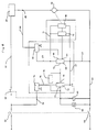
- Fig. 5 Shown in Fig. 5 is an electric circuit diagram of the described safety device.
- This device substantially comprises an electronic control stage constituted by an electronic comparator 28 connected to the electric circuit of the machine together with breaker switch 27, motor 10 and a program timing unit 29 provided for selecting the duration and the maximum temperature of a drying cycle in view of the type and amount of the fabrics introduced into drum 9.
- comparator 28 is supplied from the main conductors 30 and 31 of the electric circuit of the machine through a rectifying and voltage limiting circuit 32 and conductors 33 and 34.
- Program timing unit 29 on its part is connected to main conductor 30 through a manually operable breaker switch 35 of the normally-open type, and to main conductor 31 through the electric motor 10 for rotating drum 9.
- Comparator 28 has a DC reference voltage of a predetermined level applied to a first input terminal 36 connected to this purpose to circuit 32 adapted to also supply this reference voltage, a second input terminal 37 being connected to the juncture 38 between program timing unit 29 and motor 10 through a rectifying and voltage limiter circuit 39, a logic AND gate 40 supplied from mains, a time-constant circuit 41 of conventional type, and a limiting resistor 42.
- This second input terminal 37 is additionally adapted to be connected to ground 43 by means of a mobile contact 44 of breaker switch 27, associated to a further mobile contact 45 adapted to be actuated contemporaneously to the same operative positions and adapted to be connected to main conductor 30 parallel to manually operable breaker switch 35.
- Logic AND gate 40 on its part has a first and a second input terminal 46 and 47 connected respectively to rectifying and voltage limiter circuits 32 and 39 through conductors 33 and 48, respectively, and an output terminal 49 connected to the second input terminal 37 of comparator 28 through time-constant circuit 41.
- Logic AND gate 40 serves the purpose of permitting or preventing the DC voltage generated by circuit 41 in the manner to be described to be applied to second input terminal 37 of comparator 28 in the course of the drying cycle.
- Time-constant circuit 41 is composed of a series of electric components of the R-C type (i.e. comprising resistors and capacitors) connected and dimensioned so as to establish, in the presence of a DC input voltage of a constant level, a DC output voltage of a rising level of exponential configuration to be applied to second input terminal 37 of comparator 28.
- R-C type i.e. comprising resistors and capacitors
- a specific signalling device 50 for instance a warning lamp, an acoustic warning device or the like, to which purpose said signalling device is connected between main conductor 30 and output terminal 51 of comparator 28 through a pilot stage 52 of conventional type energized by circuit 32 and connected between the latter and main conductor 31.
- the present safety device is put into operation by closing the main switch 53 of the machine and manually operable breaker switch 35 subsequent to adjusting program timing unit 29 to a drying cycle selected in view of the kind and amount of the fabrics to be dried and introduced into the drum.
- the energization of program timing unit 29 permits the energization of motor 10, of the remaining electric components of the machine required for controlling the selected drying cycle, and of rectifying and voltage limiter circuits 32 and 39, comparator 28, pilot stage 52 and logic AND gate 40.
- the first input terminal 36 of comparator 28, the output 51 of which is initially in the disabled state, is supplied with the reference voltage generated by circuit 32, while second input 37 of comparator 28 is supplied with the voltage generated by circuit 39 through limiting resistor 42, time-constant circuit 41 and logic AND gate 40, the output 49 of which is switched to the conductive state as soon as the voltages generated by circuits 32 and 39, respectively, are applied to its input terminals 46 and 47.
- flyweights 23 Only after flyweights 23 are fully expanded they cause mobile contacts 44 and 45 of breaker switch 27 to be ccntemporaneously closed to thereby connect second input 37 of comparator 28 to ground 43 while maintaining the power supply to the electric circuit of the machine also after manually operable breaker switch 35 has been released.
- Comparator 28 is thus maintained in the non-conductive state, so that signalling device 50 remains deenergized during the full drying cycle.
- tension roller 16 is no longer rotated by motor 10 and thus comes to a standstill, as a result of which flyweights 23 return to their non-expanded rest position, while motor 10 remains in operation.
- program-timing unit 29 and motor 10 being deenergized, and the connection of second input 37 of comparator 28 to ground 43 and time-constant circuit 41 to be interrupted.
- the present safety device further includes a feedback circuit 54 connected between output 51 and second input 37 of comparator 28.
- This feedback circuit may for instance comprise a diode (not shown) conductive in the direction towards second input 37 of comparator 28, and at least one resistor (not shown) connected in series with said diode for constantly applying to input 37 a voltage higher than that applied to first input 36 of comparator 28.
- comparator 28 remains always in the conductive state to thereby maintain signalling device 50 energized through pilot stage 52.
- the present safety device is also capable of indicating in a similar manner as described above a state of malfunction caused by excessive elongation of transmission belt 14, as a result of which drum 9 comes to a standstill or continues to be rotated at a reduced speed insufficient for maintaining flyweights 23 in their expanded state, with the resultant danger of the laundry being damaged for the reasons given above.
- FIG. 4 With reference to Fig. 4, there is shown a second embodiment of the safety device according to the invention.
- the safety device comprises an element for detecting the rotational speed of tension roller 16.
- a small permanent magnet 55, a coloured or reflective lamina or a similar element of a per se known type is secured to stop disc 22 of tension roller 16 at a position facing towards shield 20 of motor 10, to cooperate with a stationary transducer 56.
- This transducer particularly comprises a conventional magnetic and/or optical sensor (including for instance light-emitting diodes and a phototransistor or similar electronic components) or other suitable elements of a per se known type, and is mounted at a position opposite element 55.
- a conventional magnetic and/or optical sensor including for instance light-emitting diodes and a phototransistor or similar electronic components
- other suitable elements of a per se known type and is mounted at a position opposite element 55.
- the described detector element is capable of detecting whether or not tension roller 16 is being rotated, by means of sensor 56 directly responsive to the corresponding rotation of element 55.
- This sensor is thus effective to generate an electric voltage corresponding to the rotational speed of tension roller 16, and to transmit this electric voltage to the electric circuit of the laundry drier via a transmission cable 57 connected between said electric circuit and a connector 58 associated to sensor 56.
- Fig. 6 depicts the electric circuit diagram of this second embodiment of the safety device.
- This electric circuit substantially comprises an electronic control stage constituted by a conventional electronic NAND gate 59 connected to the electric circuit for the purpose and in the manner to be described, together with a control relay 60, a signalling device 50 of the type described above, the program-timing unit 29 of the machine, the electric motor 10 and the above described transducer 56.
- Program-timing unit 29 is connected to main conductor 61 by a breaker switch 62 adapted to be actuated by control relay 60, and to main conductor 63 through the electric motor 10 provided for rotating drum 9.
- NAND gate 59 on its part is energized from the mains via a conductor 64 connected to the junction 65 between program-timing unit 29 an motor 10 through a rectifying and voltage limiter circuit 66, and via a common conductor 67.
- a first input 68 of NAND gate 59 is also connected to junction 65, likewise through rectifying and voltage limiting circuit 66, a second input 69 being connected to transducer 56 through a circuit 70 adapted to amplify and process the electric signal generated by transducer 56 in the manner described above, and to thereby apply a corresponding DC voltage to second input 69.
- Transducer 56 and circuit 70 on their part are energized in parallel to one another by rectifying and voltage limiter circuit 66 via conductors 64, 71 and 67.
- NAND gate 59 serves the purpose of comparing the DC voltage applied to its second input 69 and generated in the manner described to a constant-level DC reference voltage applied to its first input 68 through circuit 66, enabling the electric circuit of the machine to be energized and deenergized during the drying cycle in response to the logic state of the output 72 of NAND gate 59 determined by this comparison.
- Output 72 of NAND gate 59 on its part is connected to main conductor 63 through a driver circuit 73 of a conventional type and control relay 60 itself connected in parallel to signalling device 50, said driver circuit being energized from the mains through a rectifying and voltage limiter circuit 74 and via conductors 75 and 67.
- the thus composed safety device operates as follows: At the beginning, the main switch 53 of the electric circuit of the present laundry drier is closed after adjusting program-timing unit 29 to the temperature and the maximum duration of the selected drying cycle in accordance with the type and the quantity of the laundered fabrics introduced into the drum.
- control relay 60 is deenergized to thereby keep breaker switch 62 in the closed state, as a result of which program-timing unit 29 is energized and permits motor 10 and/or the heater element and the blower (both of which are not shown) to be likewise energized.
- transmission belt 14 starts to rotate tension roller 16 together with element 55 secured thereto.
- transducer 56 In response to the rotation of element 55, transducer 56 generates a corresponding electric signal which is amplified by circuit 70 and converted to a DC voltage of a practically constant level to be applied to second input 69 of NAND gate 59.
- tension roller 16 is no longer rotated by motor 10 and thus comes to a standstill while motor 10 continues to operate for the time being.
- This malfunction state of the machine is indicated by the energization of signalling device 50 to thereby casue the malfunction to be attended to.
- the present safety device is provided with a feedback circuit 76 connected between output 77 and input 78 of driver circuit 73.
- this feedback circuit may comprise a diode (not shown) conductive in the direction towards input 78 of driver circuit 73, and at least one resistor (not shown) connected in series with the diode for always maintaining the input of the driver circuit at the same logic state as its output 77.
- relay 60 is maintained energized to keep breaker switch 62 in the open state, while signalling device 50 on its part remains energized.
- Another state of malfunction of the present laundry drier could also be brought about by excessive elongation of transmission belt 14, as a result of which the rotation of drum 9 could come to a standstill or be continued at a reduced speed, so that there is again the danger of the laundry being damaged for the reasons explained above.
- transducer 56 operates to generate an electric signal at a reduced level
- input 69 of NAND gate 59 has no voltage applied thereto, because circuit 70 is designed and dimensioned in such a manner that it does not produce any output voltage in the presence of this electric signal supplied thereto at said reduced level.
- NAND gate 59 causes relay 60 to be energized for opening breaker switch 62, and signalling device 50 to be energized in the manner explained above.
Claims (6)
- Wäschetrockner, enthaltend ein Gebläse (12) und wenigstens ein Heizelement zum Erzeugen einer Heißluftströmung durch eine Leitung (13) in das Innere einer Trommel (9), die die zu trocknende Wäsche enthält und dazu eingerichtet ist, von einem Elektromotor (10) mit Hilfe eines Treibriemens (14) angetrieben zu werden, wobei der Treibriemen (14) durch wenigstens eine Spannrolle (16) unter Spannung gehalten wird, die in den Wäschetrockner montiert und dazu eingerichtet ist, von dem Treibriemen (14) in Drehung versetzt zu werden und im Falle eines Bruchs desselben nicht gedreht zu werden, wobei der Trockner weiterhin eine elektrische Schaltung enthält, die mit dem Gebläse (12), dem Heizelement, dem Motor (10), einer Programmsteuereinheit (29) zum Auswählen der Dauer und der Maximaltemperatur eines Trocknungszyklus verbunden ist, wobei die Programmsteuereinheit (29) mit einem elektrischen Unterbrecherschalter (27;62) verbunden ist, der durch die Spannrolle (26) betätigt wird, um den Motor (10) und das Heizelement ein- bzw. auszuschalten, wenn die Spannrolle (16) rotiert oder bzw. nicht ausreichend rotiert, dadurch gekennzeichnet, daß er eine Steuereinrichtung (28;59) enthält, die mit einer Signalvorrichtung (50) verbunden ist und dazu dient, diese aus- und einzuschalten, wenn der Motor (10) und das Heizelement (29) ein- bzw. ausgeschaltet sind.
- Wäschetrockner nach Anspruch 1, bei dem die Spannrolle (16) mechanisch mit einem Satz radial auslenkbarer Fliehgewichte (23) gekoppelt ist, die mit dem elektrischen Unterbrecherschalter (27) zusammenwirken,dadurch gekennzeichnet, daß die Steuereinrichtung einen elektronischen Komparator (28) üblicher Bauart enthält, der mit dem Unterbrecherschalter (27) verbunden ist und einen ersten (36) und einen zweiten (37) Eingang aufweist, die mit einer Gleichbezugsspannung vorbestimmten Pegels bzw. einer exponentiell ansteigenden Gleichspannung versorgt sind, und der einen Ausgang (51) aufweist, der mit der Signalvorrichtung (50) über eine Steuerstufe (52) üblicher Bauart verbunden ist, wobei der elektronische Komparator (28) dazu dient, die Signalvorrichtung (50) über die Steuerstufe (52) nur dann einzuschalten, wenn die exponentiell ansteigende Gleichspannung, die dem zweiten Eingang (37) zugeführt ist, über die Gleichbezugsspannung steigt, die dem ersten Eingang (36) zugeführt ist.
- Wäschetrockner nach Anspruch 2, dadurch gekennzeichnet, daß der zweite Eingang (37) des Komparators (28) mit dem Elektromotor (10) und der Programmsteuereinheit (29) über eine logische Und-Schaltung (50), ein Zeitglied (41) üblicher Bauart zur Erzeugung der exponentiell ansteigenden Gleichspannung und einen Begrenzungstransistor (42) verbunden ist, und der zweite Eingang (37) zur Verbindung mit Masse (53) mittels des Unterbrecherschalters (27) eingerichtet ist.
- Wäschetrockner nach Anspruch 3, dadurch gekennzeichnet, daß er eine Rückkopplungsschaltung (54) an sich bekannter Art aufweist, die zwischen den Ausgang (51) und den zweiten Eingang (37) des Komparators (28) geschaltet ist, um den zweiten Eingang (37) auf einem höheren Spannungspegel zu halten, als der erste Eingang (36), wenn eine Spannung an dem Ausgang (51) erscheint.
- Wäschetrockner nach Anspruch 1, bei dem die Spannrolle (16) mechanisch mit einem Element (55) in Form eines Permanentmagneten, einer gefärbten Lamelle oder dergleichen gekoppelt ist, welches Element (55) einem Wandler (56) an sich bekannter Art zugeordnet ist, der dazu dient, eine entsprechende elektrische Spannung in Übereinstimmung mit der Drehgeschwindigkeit der Spannrolle (16) zu erzeugen, dadurch gekennzeichnet, daß die Steuereinrichtung eine elektronische Nand-Schaltung (59) üblicher Bauart enthält, die mit einem ersten (68) und einem zweiten (69) Eingang versehen ist, die mit dem Elektromotor (10) zusammen mit der Programmsteuereinheit (29) und mit dem Wandler (56) verbunden sind, und die einen Ausgang (72) aufweist, der über eine Treiberschaltung (73) mit einem Steuerrelais (60) verbunden ist, das der Signalvorrichtung (50) parallel geschaltet ist und dem Unterbrecherschalter (62) zugeordnet ist, wobei die Nand-Schaltung (59) dazu dient, das Relais (60) über die Treiberschaltung (73) in Abhängigkeit von einem Vergleich einer Gleichbezugsspannung konstanten Pegels mit der Gleichspannung, die von dem Wandler (56) erzeugt wird und die im ersten (68) bzw. dem zweiten (69) Eingang zugeführt werden, zu steuern.
- Wäschetrockner nach Anspruch 5, dadurch gekennzeichnet, daß er eine Rückkopplungsschaltung (76) an sich bekannter Art aufweist, die zwischen den Ausgang (77) und den Eingang (78) der Treiberschaltung (73) geschaltet ist.
Applications Claiming Priority (2)
| Application Number | Priority Date | Filing Date | Title |
|---|---|---|---|
| IT45747/87A IT1220064B (it) | 1987-10-14 | 1987-10-14 | Dispositivo di sicurezza per macchina asciugabiancheria |
| IT4574787 | 1987-10-14 |
Publications (2)
| Publication Number | Publication Date |
|---|---|
| EP0312065A1 EP0312065A1 (de) | 1989-04-19 |
| EP0312065B1 true EP0312065B1 (de) | 1993-01-13 |
Family
ID=11258026
Family Applications (1)
| Application Number | Title | Priority Date | Filing Date |
|---|---|---|---|
| EP88117058A Expired - Lifetime EP0312065B1 (de) | 1987-10-14 | 1988-10-13 | Sicherheitsvorrichtung für einen Wäschetrockner |
Country Status (3)
| Country | Link |
|---|---|
| EP (1) | EP0312065B1 (de) |
| DE (1) | DE3877496T2 (de) |
| IT (1) | IT1220064B (de) |
Families Citing this family (9)
| Publication number | Priority date | Publication date | Assignee | Title |
|---|---|---|---|---|
| DE10226911B4 (de) * | 2002-06-17 | 2016-06-09 | Marquardt Gmbh | Sensor für Riemenriß |
| DE10239493A1 (de) * | 2002-08-28 | 2004-03-11 | BSH Bosch und Siemens Hausgeräte GmbH | Wäschebehandlungsgerät |
| DE102004019700B3 (de) * | 2004-04-20 | 2005-06-30 | Miele & Cie. Kg | Verfahren und Vorrichtung zur Erkennung von Betriebszuständen in einem elektronisch gesteuerten Wäschetrockner |
| DE102005048890A1 (de) * | 2005-10-12 | 2007-04-19 | BSH Bosch und Siemens Hausgeräte GmbH | Haushaltswäschetrockner und Verfahren zum Erkennen einer Drehbewegung einer Trommel |
| KR101218031B1 (ko) | 2006-10-09 | 2013-01-02 | 엘지전자 주식회사 | 건조기의 제어 방법 |
| EP2053153A1 (de) * | 2007-10-25 | 2009-04-29 | Electrolux Home Products Corporation N.V. | Waschmaschine |
| US8245415B2 (en) | 2009-12-18 | 2012-08-21 | Whirlpool Corporation | Method for determining load size in a clothes dryer using an infrared sensor |
| US8549770B2 (en) | 2009-12-18 | 2013-10-08 | Whirlpool Corporation | Apparatus and method of drying laundry with drying uniformity determination |
| US9580860B2 (en) | 2009-12-18 | 2017-02-28 | Whirlpool Corporation | Method for operating a clothes dryer using load temperature determined by an infrared sensor |
Family Cites Families (4)
| Publication number | Priority date | Publication date | Assignee | Title |
|---|---|---|---|---|
| DE1585985A1 (de) * | 1964-09-18 | 1969-10-02 | Siemens Elektrogeraete Gmbh | Nach dem Trommelprinzip arbeitender Waeschetrockner |
| US3890719A (en) * | 1974-01-25 | 1975-06-24 | Whirlpool Co | Broken belt power-disconnect system for dryers |
| FR2370283A1 (fr) * | 1976-11-05 | 1978-06-02 | Thomson Brandt | Dispositif electronique de controle d'un mouvement rotatif et circuit de securite comportant un tel dispositif |
| US4488363A (en) * | 1983-04-06 | 1984-12-18 | Whirlpool Corporation | Combination idler and belt failure switch for a dryer |
-
1987
- 1987-10-14 IT IT45747/87A patent/IT1220064B/it active
-
1988
- 1988-10-13 EP EP88117058A patent/EP0312065B1/de not_active Expired - Lifetime
- 1988-10-13 DE DE8888117058T patent/DE3877496T2/de not_active Expired - Fee Related
Also Published As
| Publication number | Publication date |
|---|---|
| DE3877496T2 (de) | 1993-05-13 |
| IT8745747A0 (it) | 1987-10-14 |
| EP0312065A1 (de) | 1989-04-19 |
| IT1220064B (it) | 1990-06-06 |
| DE3877496D1 (de) | 1993-02-25 |
Similar Documents
| Publication | Publication Date | Title |
|---|---|---|
| EP0312065B1 (de) | Sicherheitsvorrichtung für einen Wäschetrockner | |
| CA1238486A (en) | Combination idler and belt failure switch for a dryer | |
| US7536807B2 (en) | Method and device for safe operation of a program-controlled laundry drier | |
| US2882610A (en) | Control system for clothes dryers | |
| EP0312072B1 (de) | Sicherheitsvorrichtung für einen Wäschetrockner | |
| US4531307A (en) | Fabric dryer control with cycle interrupt | |
| US2736970A (en) | Laundry dryers | |
| US3571941A (en) | Appliance control circuit | |
| US3266168A (en) | Domestic dryer apparatus | |
| KR20170099292A (ko) | 세탁기 및 이의 제어방법 | |
| US2950009A (en) | Unbalance correcting arrangement for laundry machines | |
| US3210862A (en) | Dryer control system | |
| US2796679A (en) | Autoamtic clothes dryer control | |
| US2623979A (en) | Motor control device | |
| US3398461A (en) | Dryer with antiwrinkle cycle | |
| US3394465A (en) | Dryer with anti-werinkle cycle | |
| US11773530B2 (en) | Laundry appliance utilizing a permanent split capacitor motor having a sensor for providing temperature control within the appliance | |
| US2296263A (en) | Cleaning apparatus | |
| US3116983A (en) | Electric dryer control circuit | |
| US3286363A (en) | Fabric dryer controls | |
| US2967621A (en) | Unbalance correcting system for use in laundry machines | |
| US3234449A (en) | Laundry apparatus with improved control | |
| WO2008077968A1 (en) | A washer / dryer with drive belt breakage detection | |
| US3018560A (en) | Clothes drying machine | |
| US5416400A (en) | Gas dryer conversion circuit |
Legal Events
| Date | Code | Title | Description |
|---|---|---|---|
| PUAI | Public reference made under article 153(3) epc to a published international application that has entered the european phase |
Free format text: ORIGINAL CODE: 0009012 |
|
| AK | Designated contracting states |
Kind code of ref document: A1 Designated state(s): DE FR GB IT SE |
|
| 17P | Request for examination filed |
Effective date: 19891004 |
|
| 17Q | First examination report despatched |
Effective date: 19910308 |
|
| ITF | It: translation for a ep patent filed |
Owner name: PROPRIA PROTEZIONE PROPR. IND. |
|
| GRAA | (expected) grant |
Free format text: ORIGINAL CODE: 0009210 |
|
| AK | Designated contracting states |
Kind code of ref document: B1 Designated state(s): DE FR GB IT SE |
|
| ET | Fr: translation filed | ||
| REF | Corresponds to: |
Ref document number: 3877496 Country of ref document: DE Date of ref document: 19930225 |
|
| PG25 | Lapsed in a contracting state [announced via postgrant information from national office to epo] |
Ref country code: GB Effective date: 19931013 |
|
| PG25 | Lapsed in a contracting state [announced via postgrant information from national office to epo] |
Ref country code: SE Effective date: 19931014 |
|
| PLBE | No opposition filed within time limit |
Free format text: ORIGINAL CODE: 0009261 |
|
| STAA | Information on the status of an ep patent application or granted ep patent |
Free format text: STATUS: NO OPPOSITION FILED WITHIN TIME LIMIT |
|
| 26N | No opposition filed | ||
| GBPC | Gb: european patent ceased through non-payment of renewal fee |
Effective date: 19931013 |
|
| PG25 | Lapsed in a contracting state [announced via postgrant information from national office to epo] |
Ref country code: FR Effective date: 19940630 |
|
| PG25 | Lapsed in a contracting state [announced via postgrant information from national office to epo] |
Ref country code: DE Effective date: 19940701 |
|
| REG | Reference to a national code |
Ref country code: FR Ref legal event code: ST |
|
| EUG | Se: european patent has lapsed |
Ref document number: 88117058.3 Effective date: 19940510 |
|
| PG25 | Lapsed in a contracting state [announced via postgrant information from national office to epo] |
Ref country code: IT Free format text: LAPSE BECAUSE OF NON-PAYMENT OF DUE FEES;WARNING: LAPSES OF ITALIAN PATENTS WITH EFFECTIVE DATE BEFORE 2007 MAY HAVE OCCURRED AT ANY TIME BEFORE 2007. THE CORRECT EFFECTIVE DATE MAY BE DIFFERENT FROM THE ONE RECORDED. Effective date: 20051013 |