EP0312065B1 - Safety device for a laundry drier - Google Patents
Safety device for a laundry drier Download PDFInfo
- Publication number
- EP0312065B1 EP0312065B1 EP88117058A EP88117058A EP0312065B1 EP 0312065 B1 EP0312065 B1 EP 0312065B1 EP 88117058 A EP88117058 A EP 88117058A EP 88117058 A EP88117058 A EP 88117058A EP 0312065 B1 EP0312065 B1 EP 0312065B1
- Authority
- EP
- European Patent Office
- Prior art keywords
- input
- voltage
- circuit
- tension roller
- electric
- Prior art date
- Legal status (The legal status is an assumption and is not a legal conclusion. Google has not performed a legal analysis and makes no representation as to the accuracy of the status listed.)
- Expired - Lifetime
Links
Images


Classifications
-
- D—TEXTILES; PAPER
- D06—TREATMENT OF TEXTILES OR THE LIKE; LAUNDERING; FLEXIBLE MATERIALS NOT OTHERWISE PROVIDED FOR
- D06F—LAUNDERING, DRYING, IRONING, PRESSING OR FOLDING TEXTILE ARTICLES
- D06F58/00—Domestic laundry dryers
- D06F58/02—Domestic laundry dryers having dryer drums rotating about a horizontal axis
- D06F58/04—Details
- D06F58/08—Driving arrangements
-
- D—TEXTILES; PAPER
- D06—TREATMENT OF TEXTILES OR THE LIKE; LAUNDERING; FLEXIBLE MATERIALS NOT OTHERWISE PROVIDED FOR
- D06F—LAUNDERING, DRYING, IRONING, PRESSING OR FOLDING TEXTILE ARTICLES
- D06F2103/00—Parameters monitored or detected for the control of domestic laundry washing machines, washer-dryers or laundry dryers
- D06F2103/02—Characteristics of laundry or load
- D06F2103/04—Quantity, e.g. weight or variation of weight
-
- D—TEXTILES; PAPER
- D06—TREATMENT OF TEXTILES OR THE LIKE; LAUNDERING; FLEXIBLE MATERIALS NOT OTHERWISE PROVIDED FOR
- D06F—LAUNDERING, DRYING, IRONING, PRESSING OR FOLDING TEXTILE ARTICLES
- D06F2103/00—Parameters monitored or detected for the control of domestic laundry washing machines, washer-dryers or laundry dryers
- D06F2103/02—Characteristics of laundry or load
- D06F2103/06—Type or material
-
- D—TEXTILES; PAPER
- D06—TREATMENT OF TEXTILES OR THE LIKE; LAUNDERING; FLEXIBLE MATERIALS NOT OTHERWISE PROVIDED FOR
- D06F—LAUNDERING, DRYING, IRONING, PRESSING OR FOLDING TEXTILE ARTICLES
- D06F2103/00—Parameters monitored or detected for the control of domestic laundry washing machines, washer-dryers or laundry dryers
- D06F2103/24—Spin speed; Drum movements
-
- D—TEXTILES; PAPER
- D06—TREATMENT OF TEXTILES OR THE LIKE; LAUNDERING; FLEXIBLE MATERIALS NOT OTHERWISE PROVIDED FOR
- D06F—LAUNDERING, DRYING, IRONING, PRESSING OR FOLDING TEXTILE ARTICLES
- D06F2103/00—Parameters monitored or detected for the control of domestic laundry washing machines, washer-dryers or laundry dryers
- D06F2103/38—Time, e.g. duration
-
- D—TEXTILES; PAPER
- D06—TREATMENT OF TEXTILES OR THE LIKE; LAUNDERING; FLEXIBLE MATERIALS NOT OTHERWISE PROVIDED FOR
- D06F—LAUNDERING, DRYING, IRONING, PRESSING OR FOLDING TEXTILE ARTICLES
- D06F2103/00—Parameters monitored or detected for the control of domestic laundry washing machines, washer-dryers or laundry dryers
- D06F2103/44—Current or voltage
-
- D—TEXTILES; PAPER
- D06—TREATMENT OF TEXTILES OR THE LIKE; LAUNDERING; FLEXIBLE MATERIALS NOT OTHERWISE PROVIDED FOR
- D06F—LAUNDERING, DRYING, IRONING, PRESSING OR FOLDING TEXTILE ARTICLES
- D06F34/00—Details of control systems for washing machines, washer-dryers or laundry dryers
- D06F34/08—Control circuits or arrangements thereof
-
- D—TEXTILES; PAPER
- D06—TREATMENT OF TEXTILES OR THE LIKE; LAUNDERING; FLEXIBLE MATERIALS NOT OTHERWISE PROVIDED FOR
- D06F—LAUNDERING, DRYING, IRONING, PRESSING OR FOLDING TEXTILE ARTICLES
- D06F37/00—Details specific to washing machines covered by groups D06F21/00 - D06F25/00
- D06F37/42—Safety arrangements, e.g. for stopping rotation of the receptacle upon opening of the casing door
-
- D—TEXTILES; PAPER
- D06—TREATMENT OF TEXTILES OR THE LIKE; LAUNDERING; FLEXIBLE MATERIALS NOT OTHERWISE PROVIDED FOR
- D06F—LAUNDERING, DRYING, IRONING, PRESSING OR FOLDING TEXTILE ARTICLES
- D06F58/00—Domestic laundry dryers
- D06F58/32—Control of operations performed in domestic laundry dryers
- D06F58/34—Control of operations performed in domestic laundry dryers characterised by the purpose or target of the control
- D06F58/50—Responding to irregular working conditions, e.g. malfunctioning of blowers
Definitions
- the invention relates to a laundry dryer and in particular to a safety device for a laundry drier adapted to interrupt the electric power supply to the machine whenever the drum is not properly rotated by the associated electric motor, in the case for instance of rupture or excessive elongation of the transmission belt connected between the drum and the electric motor.
- Known laundry driers substantially comprise a blower and at least one heater element operable to establish a circulation of hot air through a conduit containing a filter for retaining fluff and any possible foreign bodies to the interior of a drum containing the laundry to be dried and adapted to be rotated by an electric motor with the aid of a transmission belt connected between the drum and the electric motor.
- electro-mechanical safety devices For preventing such malfunctions from occurring, electro-mechanical safety devices have already been proposed, such safety devices being operable to interrupt the electric power supply to the machine in response to rupture or excessive elongation of the transmission belt.
- the bracket is resiliently biased by the tension of the transmission belt towards an operative position to thereby keep the breaker switch in the closed state ensuring the continued supply of electric power to the machine.
- the bracket In the case of possible rupture or excessive elongation of the belt, however, the bracket is no longer biased by the tension of the belt and thus permitted to assume an alternative operative position, causing the breaker switch to open and to thereby interupt the power supply to the machine.
- This safety device is employed in a laundry washing machine comprising a tension roller acting on the transmission belt and carried by a spring-biased lever mounted on the base of the machine and acting on a breaker switch incorporated in the electric power supply circuit of the machine.
- these known safety devices are not capable of interrupting the electric power supply to the respective machine in the possible case of damage or malfunction of the belt tensioning mechanism (comprising the elastic bracket or the spring-biased lever, respectively) so that in this case the electric power supply to the machine is continued although the drum might have come to a standstill or might be rotated at a reduced speed.
- a laundry drier having a combination idler and belt failure switch associated to a pulley engaged by a belt by means of which the drum of the drier is driven by a motor.
- An idler pulley is supported and biased by a bracket to maintain tension of the belt.
- linkage means are provided interconnecting the idler pulley and the centrifugal switch for deactuating said switch to cease operation of the motor in response to the breaking of the belt.
- power supply to heater elements is controlled by the same switch, heating is interrupted as well upon deactuation of the switch.
- a control device for a rotational movement of a turning member in an apparatus like a laundry washing-machine comprising electronic means for detecting the rotational speed of the rotating member which may be a pulley to drive a drum.
- the detector is formed by a magnetic coil connected to an electronic circuit, and the coil is influenced by a magnet disposed at the rotating member. If rotational speed of the rotating member does not exceed the predetermined threshhold, heating elements of the washing-machine are switched off or a programme unit is controlled to attain its initial position in which all power to the electric components of the washing-machine is switched off.
- the known arrangements suffer from suitably indicating any condition of disorder of the machine, so that it is the object of the invention to provide a laundry drier permitting to signal automatically the correct or incorrect operation of the drier through suitable control means.
- a lower portion of a laundry drier 7 having a housing 8 surrounding a drum 9 adapted to be rotated by an electric motor 10 of conventional construction mounted on the base 11 of the machine.
- the present laundry drier also comprises a blower 12 connected to a conduit 13 leading to the interior of drum 9 and defined between the walls of housing 8 and the drum 9 itself.
- conduit 13 Mounted within conduit 13 are at least one heater element and a filter of conventional construction (both of which are not shown), adapted respectively to heat the flow of air produced by blower 12, and to retain fluff and any foreign bodies possibly entrained by the air flow.
- Drum 9 of the described machine on its part is adapted to be rotated by electric motor 10, preferably in a single direction, with the aid of a transmission belt 14 extending between a driving pulley 15 associated to motor 10 and a driven pulley formed by or on the circumferential surface of drum 9.
- transmission belt 14 is kept under tension by at least one tension roller 16 of conventional type to thereby ensure the efficient transmission of the driving force from motor 10 to drum 9, said tension roller 16 being mounted in a lower portion of the machine in the manner to be described.
- FIG. 2 With reference now to Figs. 2 and 3, there is shown a first embodiment of a safety device according to the invention.
- tension roller 16 has a centrally mounted extended shaft 17 adapted to extend through the bore (not shown) of a slide bushing 18 and through a corresponding bore (not shown) drilled in a projection 19 of the front shield 20 of motor 10.
- This tension roller 16 is further provided with two lateral stop disks 21 and 22 adapted to prevent any lateral displacement of transmission belt 14 during operation of the machine.
- Tension roller 16 is thus mounted in the bore of projection 19 in a freely rotatable manner and in pressure contact with transmission belt 14 due to the tension of the latter, so as to be rotated by the movement of the belt during operation of the machine.
- the present safety device comprises a set of radial-expansion flyweights 23 connected at one end to stop disk 22 and biased away from one another by compression springs 24, their other ends being engaged with the cylindrical outer surface of slide bushing 18.
- flyweights 23 are caused to expand radially as shown in fig. 2.
- flyweights 23 thus assume an operative position to thereby cause slide bushing 18 to be axially displaced on shaft 17 to a position in which a further disc 25 carried by its free end is located closely adjacent projection 19.
- disc 25 acts on an actuator arm 26 of an electric breaker switch 27 incorporated in the electric circuit of the machine in a manner to be described, to thereby close the mobile contacts (not shown) of breaker switch 27 by the action thereon of actuator arm 26.
- tension roller 16 When on the other hand tension roller 16 is not rotated, or is rotated at a reduced speed below the above specified limits,, i.e. in the case of rupture or excessive elongation of transmission belt 14, under a condition thus, in which drum 9 has come to a standstill or is rotated at a considerably reduced speed, resulting in the danger of the laundry being damaged by the flow of heated air directed through the drum, flyweights 23 assume their rest position as shown in fig. 3, in which they are not radially expanded.
- flyweights 23 are automatically returned to their rest position by the resilient action thereon of compression springs 24, causing axial displacement of slide bushing 18 towards tension roller 16, see Fig.3.
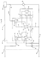
- Fig. 5 Shown in Fig. 5 is an electric circuit diagram of the described safety device.
- This device substantially comprises an electronic control stage constituted by an electronic comparator 28 connected to the electric circuit of the machine together with breaker switch 27, motor 10 and a program timing unit 29 provided for selecting the duration and the maximum temperature of a drying cycle in view of the type and amount of the fabrics introduced into drum 9.
- comparator 28 is supplied from the main conductors 30 and 31 of the electric circuit of the machine through a rectifying and voltage limiting circuit 32 and conductors 33 and 34.
- Program timing unit 29 on its part is connected to main conductor 30 through a manually operable breaker switch 35 of the normally-open type, and to main conductor 31 through the electric motor 10 for rotating drum 9.
- Comparator 28 has a DC reference voltage of a predetermined level applied to a first input terminal 36 connected to this purpose to circuit 32 adapted to also supply this reference voltage, a second input terminal 37 being connected to the juncture 38 between program timing unit 29 and motor 10 through a rectifying and voltage limiter circuit 39, a logic AND gate 40 supplied from mains, a time-constant circuit 41 of conventional type, and a limiting resistor 42.
- This second input terminal 37 is additionally adapted to be connected to ground 43 by means of a mobile contact 44 of breaker switch 27, associated to a further mobile contact 45 adapted to be actuated contemporaneously to the same operative positions and adapted to be connected to main conductor 30 parallel to manually operable breaker switch 35.
- Logic AND gate 40 on its part has a first and a second input terminal 46 and 47 connected respectively to rectifying and voltage limiter circuits 32 and 39 through conductors 33 and 48, respectively, and an output terminal 49 connected to the second input terminal 37 of comparator 28 through time-constant circuit 41.
- Logic AND gate 40 serves the purpose of permitting or preventing the DC voltage generated by circuit 41 in the manner to be described to be applied to second input terminal 37 of comparator 28 in the course of the drying cycle.
- Time-constant circuit 41 is composed of a series of electric components of the R-C type (i.e. comprising resistors and capacitors) connected and dimensioned so as to establish, in the presence of a DC input voltage of a constant level, a DC output voltage of a rising level of exponential configuration to be applied to second input terminal 37 of comparator 28.
- R-C type i.e. comprising resistors and capacitors
- a specific signalling device 50 for instance a warning lamp, an acoustic warning device or the like, to which purpose said signalling device is connected between main conductor 30 and output terminal 51 of comparator 28 through a pilot stage 52 of conventional type energized by circuit 32 and connected between the latter and main conductor 31.
- the present safety device is put into operation by closing the main switch 53 of the machine and manually operable breaker switch 35 subsequent to adjusting program timing unit 29 to a drying cycle selected in view of the kind and amount of the fabrics to be dried and introduced into the drum.
- the energization of program timing unit 29 permits the energization of motor 10, of the remaining electric components of the machine required for controlling the selected drying cycle, and of rectifying and voltage limiter circuits 32 and 39, comparator 28, pilot stage 52 and logic AND gate 40.
- the first input terminal 36 of comparator 28, the output 51 of which is initially in the disabled state, is supplied with the reference voltage generated by circuit 32, while second input 37 of comparator 28 is supplied with the voltage generated by circuit 39 through limiting resistor 42, time-constant circuit 41 and logic AND gate 40, the output 49 of which is switched to the conductive state as soon as the voltages generated by circuits 32 and 39, respectively, are applied to its input terminals 46 and 47.
- flyweights 23 Only after flyweights 23 are fully expanded they cause mobile contacts 44 and 45 of breaker switch 27 to be ccntemporaneously closed to thereby connect second input 37 of comparator 28 to ground 43 while maintaining the power supply to the electric circuit of the machine also after manually operable breaker switch 35 has been released.
- Comparator 28 is thus maintained in the non-conductive state, so that signalling device 50 remains deenergized during the full drying cycle.
- tension roller 16 is no longer rotated by motor 10 and thus comes to a standstill, as a result of which flyweights 23 return to their non-expanded rest position, while motor 10 remains in operation.
- program-timing unit 29 and motor 10 being deenergized, and the connection of second input 37 of comparator 28 to ground 43 and time-constant circuit 41 to be interrupted.
- the present safety device further includes a feedback circuit 54 connected between output 51 and second input 37 of comparator 28.
- This feedback circuit may for instance comprise a diode (not shown) conductive in the direction towards second input 37 of comparator 28, and at least one resistor (not shown) connected in series with said diode for constantly applying to input 37 a voltage higher than that applied to first input 36 of comparator 28.
- comparator 28 remains always in the conductive state to thereby maintain signalling device 50 energized through pilot stage 52.
- the present safety device is also capable of indicating in a similar manner as described above a state of malfunction caused by excessive elongation of transmission belt 14, as a result of which drum 9 comes to a standstill or continues to be rotated at a reduced speed insufficient for maintaining flyweights 23 in their expanded state, with the resultant danger of the laundry being damaged for the reasons given above.
- FIG. 4 With reference to Fig. 4, there is shown a second embodiment of the safety device according to the invention.
- the safety device comprises an element for detecting the rotational speed of tension roller 16.
- a small permanent magnet 55, a coloured or reflective lamina or a similar element of a per se known type is secured to stop disc 22 of tension roller 16 at a position facing towards shield 20 of motor 10, to cooperate with a stationary transducer 56.
- This transducer particularly comprises a conventional magnetic and/or optical sensor (including for instance light-emitting diodes and a phototransistor or similar electronic components) or other suitable elements of a per se known type, and is mounted at a position opposite element 55.
- a conventional magnetic and/or optical sensor including for instance light-emitting diodes and a phototransistor or similar electronic components
- other suitable elements of a per se known type and is mounted at a position opposite element 55.
- the described detector element is capable of detecting whether or not tension roller 16 is being rotated, by means of sensor 56 directly responsive to the corresponding rotation of element 55.
- This sensor is thus effective to generate an electric voltage corresponding to the rotational speed of tension roller 16, and to transmit this electric voltage to the electric circuit of the laundry drier via a transmission cable 57 connected between said electric circuit and a connector 58 associated to sensor 56.
- Fig. 6 depicts the electric circuit diagram of this second embodiment of the safety device.
- This electric circuit substantially comprises an electronic control stage constituted by a conventional electronic NAND gate 59 connected to the electric circuit for the purpose and in the manner to be described, together with a control relay 60, a signalling device 50 of the type described above, the program-timing unit 29 of the machine, the electric motor 10 and the above described transducer 56.
- Program-timing unit 29 is connected to main conductor 61 by a breaker switch 62 adapted to be actuated by control relay 60, and to main conductor 63 through the electric motor 10 provided for rotating drum 9.
- NAND gate 59 on its part is energized from the mains via a conductor 64 connected to the junction 65 between program-timing unit 29 an motor 10 through a rectifying and voltage limiter circuit 66, and via a common conductor 67.
- a first input 68 of NAND gate 59 is also connected to junction 65, likewise through rectifying and voltage limiting circuit 66, a second input 69 being connected to transducer 56 through a circuit 70 adapted to amplify and process the electric signal generated by transducer 56 in the manner described above, and to thereby apply a corresponding DC voltage to second input 69.
- Transducer 56 and circuit 70 on their part are energized in parallel to one another by rectifying and voltage limiter circuit 66 via conductors 64, 71 and 67.
- NAND gate 59 serves the purpose of comparing the DC voltage applied to its second input 69 and generated in the manner described to a constant-level DC reference voltage applied to its first input 68 through circuit 66, enabling the electric circuit of the machine to be energized and deenergized during the drying cycle in response to the logic state of the output 72 of NAND gate 59 determined by this comparison.
- Output 72 of NAND gate 59 on its part is connected to main conductor 63 through a driver circuit 73 of a conventional type and control relay 60 itself connected in parallel to signalling device 50, said driver circuit being energized from the mains through a rectifying and voltage limiter circuit 74 and via conductors 75 and 67.
- the thus composed safety device operates as follows: At the beginning, the main switch 53 of the electric circuit of the present laundry drier is closed after adjusting program-timing unit 29 to the temperature and the maximum duration of the selected drying cycle in accordance with the type and the quantity of the laundered fabrics introduced into the drum.
- control relay 60 is deenergized to thereby keep breaker switch 62 in the closed state, as a result of which program-timing unit 29 is energized and permits motor 10 and/or the heater element and the blower (both of which are not shown) to be likewise energized.
- transmission belt 14 starts to rotate tension roller 16 together with element 55 secured thereto.
- transducer 56 In response to the rotation of element 55, transducer 56 generates a corresponding electric signal which is amplified by circuit 70 and converted to a DC voltage of a practically constant level to be applied to second input 69 of NAND gate 59.
- tension roller 16 is no longer rotated by motor 10 and thus comes to a standstill while motor 10 continues to operate for the time being.
- This malfunction state of the machine is indicated by the energization of signalling device 50 to thereby casue the malfunction to be attended to.
- the present safety device is provided with a feedback circuit 76 connected between output 77 and input 78 of driver circuit 73.
- this feedback circuit may comprise a diode (not shown) conductive in the direction towards input 78 of driver circuit 73, and at least one resistor (not shown) connected in series with the diode for always maintaining the input of the driver circuit at the same logic state as its output 77.
- relay 60 is maintained energized to keep breaker switch 62 in the open state, while signalling device 50 on its part remains energized.
- Another state of malfunction of the present laundry drier could also be brought about by excessive elongation of transmission belt 14, as a result of which the rotation of drum 9 could come to a standstill or be continued at a reduced speed, so that there is again the danger of the laundry being damaged for the reasons explained above.
- transducer 56 operates to generate an electric signal at a reduced level
- input 69 of NAND gate 59 has no voltage applied thereto, because circuit 70 is designed and dimensioned in such a manner that it does not produce any output voltage in the presence of this electric signal supplied thereto at said reduced level.
- NAND gate 59 causes relay 60 to be energized for opening breaker switch 62, and signalling device 50 to be energized in the manner explained above.
Description
- The invention relates to a laundry dryer and in particular to a safety device for a laundry drier adapted to interrupt the electric power supply to the machine whenever the drum is not properly rotated by the associated electric motor, in the case for instance of rupture or excessive elongation of the transmission belt connected between the drum and the electric motor.
- Known laundry driers substantially comprise a blower and at least one heater element operable to establish a circulation of hot air through a conduit containing a filter for retaining fluff and any possible foreign bodies to the interior of a drum containing the laundry to be dried and adapted to be rotated by an electric motor with the aid of a transmission belt connected between the drum and the electric motor.
- In known machines of this type, the possible rupture or excessive elongation of the transmission belt, held under tension by at least one tension roller disposed at a lower rearward location of the machine, will cause the drum to come to a standstill or to be rotated at a considerably reduced speed, with the resultant danger of overheating and/or scorching of the laundry contained in the drum by the hot air flow passing through the drum.
- For preventing such malfunctions from occurring, electro-mechanical safety devices have already been proposed, such safety devices being operable to interrupt the electric power supply to the machine in response to rupture or excessive elongation of the transmission belt.
- Known in particular from US Patents 3,890,719 and 3,890,720 is such a safety device comprising a tension roller associated to the transmission belt and carried by an elastic bracket secured to the base of the machine and cooperating with a breaker switch incorporated in the electric power supply circuit of the machine.
- During normal operation of the machine, the bracket is resiliently biased by the tension of the transmission belt towards an operative position to thereby keep the breaker switch in the closed state ensuring the continued supply of electric power to the machine.
- In the case of possible rupture or excessive elongation of the belt, however, the bracket is no longer biased by the tension of the belt and thus permitted to assume an alternative operative position, causing the breaker switch to open and to thereby interupt the power supply to the machine.
- Another safety device is known from GB Patent 839,471.
- This safety device is employed in a laundry washing machine comprising a tension roller acting on the transmission belt and carried by a spring-biased lever mounted on the base of the machine and acting on a breaker switch incorporated in the electric power supply circuit of the machine.
- Also in this case a possible rupture or excessive elongation of the transmission belt causes the breaker switch to be actuated to its open position, as in the preceding case, to thereby interrupt the power supply to the machine.
- In any case, these known safety devices are not capable of interrupting the electric power supply to the respective machine in the possible case of damage or malfunction of the belt tensioning mechanism (comprising the elastic bracket or the spring-biased lever, respectively) so that in this case the electric power supply to the machine is continued although the drum might have come to a standstill or might be rotated at a reduced speed.
- As a result, the hot air continuously circulating through the drum of the laundry drier leads to a progressive over-heating of the laundry, with the danger of the laundry being scorched.
- From US-A-4 488 363 a laundry drier is known having a combination idler and belt failure switch associated to a pulley engaged by a belt by means of which the drum of the drier is driven by a motor. An idler pulley is supported and biased by a bracket to maintain tension of the belt. Further, linkage means are provided interconnecting the idler pulley and the centrifugal switch for deactuating said switch to cease operation of the motor in response to the breaking of the belt. As power supply to heater elements is controlled by the same switch, heating is interrupted as well upon deactuation of the switch. This drier is prior art according to the preamble of
claim 1. - From FR-A-2 370 283 a control device for a rotational movement of a turning member in an apparatus like a laundry washing-machine is known comprising electronic means for detecting the rotational speed of the rotating member which may be a pulley to drive a drum. The detector is formed by a magnetic coil connected to an electronic circuit, and the coil is influenced by a magnet disposed at the rotating member. If rotational speed of the rotating member does not exceed the predetermined threshhold, heating elements of the washing-machine are switched off or a programme unit is controlled to attain its initial position in which all power to the electric components of the washing-machine is switched off.
- The known arrangements suffer from suitably indicating any condition of disorder of the machine, so that it is the object of the invention to provide a laundry drier permitting to signal automatically the correct or incorrect operation of the drier through suitable control means.
- This object is obtained by the characterising features of
claim 1. Preferred embodiments of the invention are subject-matter of the dependent claims. - The characteristics of the invention will become more evident from the following description, given by way of example with reference to the accompanying drawings, wherein:
- Figure 1 shows a diagrammatic side view of the parts of a laundry drier equipped with a safety device according to the invention,
- Figures 2 and 3 show a first embodiment of the present safety device in two different operative positions,
- Fig. 4 shows a second embodiment of the present safety device, and
- Figs. 5 and 6 show an electric circuit diagram of the present safety device in a first and a second embodiment thereof, respectively.
- With reference to Fig. 1, there is shown a lower portion of a
laundry drier 7 having ahousing 8 surrounding adrum 9 adapted to be rotated by anelectric motor 10 of conventional construction mounted on the base 11 of the machine. - The present laundry drier also comprises a
blower 12 connected to aconduit 13 leading to the interior ofdrum 9 and defined between the walls ofhousing 8 and thedrum 9 itself. - Mounted within
conduit 13 are at least one heater element and a filter of conventional construction (both of which are not shown), adapted respectively to heat the flow of air produced byblower 12, and to retain fluff and any foreign bodies possibly entrained by the air flow. -
Drum 9 of the described machine on its part is adapted to be rotated byelectric motor 10, preferably in a single direction, with the aid of atransmission belt 14 extending between a drivingpulley 15 associated tomotor 10 and a driven pulley formed by or on the circumferential surface ofdrum 9. - During operation of the machine,
transmission belt 14 is kept under tension by at least onetension roller 16 of conventional type to thereby ensure the efficient transmission of the driving force frommotor 10 todrum 9, saidtension roller 16 being mounted in a lower portion of the machine in the manner to be described. - With reference now to Figs. 2 and 3, there is shown a first embodiment of a safety device according to the invention.
- As shown in these figures,
tension roller 16 has a centrally mounted extendedshaft 17 adapted to extend through the bore (not shown) of a slide bushing 18 and through a corresponding bore (not shown) drilled in aprojection 19 of thefront shield 20 ofmotor 10. - This
tension roller 16 is further provided with twolateral stop disks transmission belt 14 during operation of the machine. -
Tension roller 16 is thus mounted in the bore ofprojection 19 in a freely rotatable manner and in pressure contact withtransmission belt 14 due to the tension of the latter, so as to be rotated by the movement of the belt during operation of the machine. - According to the invention, the present safety device comprises a set of radial-
expansion flyweights 23 connected at one end to stopdisk 22 and biased away from one another bycompression springs 24, their other ends being engaged with the cylindrical outer surface of slide bushing 18. - When
tension roller 16 is rotated by the action thereon oftransmission belt 14 at a speed comprised between predetermined limits and indicative ofdrum 9 of the machine being rotated at a proper speed,flyweights 23 are caused to expand radially as shown in fig. 2. - Under these
conditions flyweights 23 thus assume an operative position to thereby cause slide bushing 18 to be axially displaced onshaft 17 to a position in which afurther disc 25 carried by its free end is located closelyadjacent projection 19. - In this
position disc 25 acts on anactuator arm 26 of anelectric breaker switch 27 incorporated in the electric circuit of the machine in a manner to be described, to thereby close the mobile contacts (not shown) ofbreaker switch 27 by the action thereon ofactuator arm 26. - This results in the machine being supplied with electric power, permitting the selected drying cycle to proceed.
- When on the other
hand tension roller 16 is not rotated, or is rotated at a reduced speed below the above specified limits,, i.e. in the case of rupture or excessive elongation oftransmission belt 14, under a condition thus, in whichdrum 9 has come to a standstill or is rotated at a considerably reduced speed, resulting in the danger of the laundry being damaged by the flow of heated air directed through the drum,flyweights 23 assume their rest position as shown in fig. 3, in which they are not radially expanded. - Under these
conditions flyweights 23 are automatically returned to their rest position by the resilient action thereon ofcompression springs 24, causing axial displacement of slide bushing 18 towardstension roller 16, see Fig.3. - The resultant displacement of
disc 25 permitsactuator arm 26 ofbreaker switch 27 to assume a second position in which the mobile contacts of the breaker switch are opened to thereby interrupt the electric power supply to the machine. - As a result, the performance of the selected drying cycle is interrupted for permitting the malfunction of the machine to be attended to.
- Shown in Fig. 5 is an electric circuit diagram of the described safety device.
- This device substantially comprises an electronic control stage constituted by an electronic comparator 28 connected to the electric circuit of the machine together with
breaker switch 27,motor 10 and aprogram timing unit 29 provided for selecting the duration and the maximum temperature of a drying cycle in view of the type and amount of the fabrics introduced intodrum 9. - In particular, comparator 28 is supplied from the
main conductors voltage limiting circuit 32 andconductors -
Program timing unit 29 on its part is connected tomain conductor 30 through a manuallyoperable breaker switch 35 of the normally-open type, and tomain conductor 31 through theelectric motor 10 for rotatingdrum 9. - Comparator 28 has a DC reference voltage of a predetermined level applied to a
first input terminal 36 connected to this purpose tocircuit 32 adapted to also supply this reference voltage, asecond input terminal 37 being connected to thejuncture 38 betweenprogram timing unit 29 andmotor 10 through a rectifying andvoltage limiter circuit 39, a logic ANDgate 40 supplied from mains, a time-constant circuit 41 of conventional type, and alimiting resistor 42. - This
second input terminal 37 is additionally adapted to be connected toground 43 by means of amobile contact 44 ofbreaker switch 27, associated to a furthermobile contact 45 adapted to be actuated contemporaneously to the same operative positions and adapted to be connected tomain conductor 30 parallel to manuallyoperable breaker switch 35. Logic ANDgate 40 on its part has a first and asecond input terminal voltage limiter circuits conductors output terminal 49 connected to thesecond input terminal 37 of comparator 28 through time-constant circuit 41. - Logic AND
gate 40 serves the purpose of permitting or preventing the DC voltage generated bycircuit 41 in the manner to be described to be applied tosecond input terminal 37 of comparator 28 in the course of the drying cycle. - Time-
constant circuit 41 is composed of a series of electric components of the R-C type (i.e. comprising resistors and capacitors) connected and dimensioned so as to establish, in the presence of a DC input voltage of a constant level, a DC output voltage of a rising level of exponential configuration to be applied tosecond input terminal 37 of comparator 28. - Depending on the comparison of this voltage to the reference voltage applied to
first input terminal 36 of comparator 28, it is possible in this manner to control the energization of aspecific signalling device 50, for instance a warning lamp, an acoustic warning device or the like, to which purpose said signalling device is connected betweenmain conductor 30 andoutput terminal 51 of comparator 28 through apilot stage 52 of conventional type energized bycircuit 32 and connected between the latter andmain conductor 31. - The present safety device is put into operation by closing the
main switch 53 of the machine and manuallyoperable breaker switch 35 subsequent to adjustingprogram timing unit 29 to a drying cycle selected in view of the kind and amount of the fabrics to be dried and introduced into the drum. - Under these
conditions motor 10 andtension roller 16 are initially at a standstill, so thatflyweights 23 are not radially expanded, andmobile contacts breaker switch 27 remain open. - The energization of
program timing unit 29 permits the energization ofmotor 10, of the remaining electric components of the machine required for controlling the selected drying cycle, and of rectifying andvoltage limiter circuits pilot stage 52 and logic ANDgate 40. - As a result, the
first input terminal 36 of comparator 28, theoutput 51 of which is initially in the disabled state, is supplied with the reference voltage generated bycircuit 32, whilesecond input 37 of comparator 28 is supplied with the voltage generated bycircuit 39 through limitingresistor 42, time-constant circuit 41 and logic ANDgate 40, theoutput 49 of which is switched to the conductive state as soon as the voltages generated bycircuits input terminals - As a result, an exponentially rising DC voltage generated by time-
constant circuit 41 is applied tosecond input 37, the level of this voltage being lower than that of the reference voltage applied tofirst input 36 of comparator 28 at least during the short period during whichbreaker switch 27 remains open before theflyweights 23 are fully expanded in the radial direction by the action ofmotor 10. - Only after
flyweights 23 are fully expanded they causemobile contacts breaker switch 27 to be ccntemporaneously closed to thereby connectsecond input 37 of comparator 28 toground 43 while maintaining the power supply to the electric circuit of the machine also after manuallyoperable breaker switch 35 has been released. - As a result, the voltage generated by
circuit 41 is applied to ground through limitingresistor 42, so that no voltage appears atsecond input 37 of comparator 28. - Comparator 28 is thus maintained in the non-conductive state, so that
signalling device 50 remains deenergized during the full drying cycle. - In the case of a possible rupture of
transmission belt 14, on the other hand,tension roller 16 is no longer rotated bymotor 10 and thus comes to a standstill, as a result of whichflyweights 23 return to their non-expanded rest position, whilemotor 10 remains in operation. - Under these conditions the rotation of
drum 9 is likewise stopped, resulting in the danger of the laundry contained therein being scorched by the flow of heated air directed therethrough, which to avoidflyweights 23 causemobile contacts breaker switch 27 to be opened. - This results in program-
timing unit 29 andmotor 10 being deenergized, and the connection ofsecond input 37 of comparator 28 to ground 43 and time-constant circuit 41 to be interrupted. - In this manner the voltage generated by time-
constant circuit 41 is applied to limitingresistor 42, the resultant voltage drop being applied tosecond input 37 of comparator 28, as a result of which, as soon as this voltage rises above the reference voltage constantly applied tofirst input 36 of comparator 28,output 51 of comparator 28 is rendered conductive to thereby energize signallingdevice 50 throughpilot stage 52. - For preventing the interruption of the power supply to program-
timing unit 29 from again inverting the logic state of comparator 28, due to the fact that time-constant circuit 41 is no longer energized, so that it no longer applies a voltage tosecond input 37 of comparator 28, resulting in undesirable deenergization of signallingdevice 50, the present safety device further includes afeedback circuit 54 connected betweenoutput 51 andsecond input 37 of comparator 28. - This feedback circuit may for instance comprise a diode (not shown) conductive in the direction towards
second input 37 of comparator 28, and at least one resistor (not shown) connected in series with said diode for constantly applying to input 37 a voltage higher than that applied tofirst input 36 of comparator 28. - In this manner, even when the machine is deenergized by the opening of
breaker switch 27, comparator 28 remains always in the conductive state to thereby maintain signallingdevice 50 energized throughpilot stage 52. - In this manner it is possible to detect the malfunction of the machine and to consequentially attend to such malfunction.
- The present safety device is also capable of indicating in a similar manner as described above a state of malfunction caused by excessive elongation of
transmission belt 14, as a result of which drum 9 comes to a standstill or continues to be rotated at a reduced speed insufficient for maintainingflyweights 23 in their expanded state, with the resultant danger of the laundry being damaged for the reasons given above. - With reference to Fig. 4, there is shown a second embodiment of the safety device according to the invention.
- In this case,
slide bushing 18 andflyweights 23 have been eliminated, theextended shaft 17 oftension roller 16 being directly received in the bore ofprojection 19. - In this embodiment of the invention, the safety device comprises an element for detecting the rotational speed of
tension roller 16. In the embodiment shown, a smallpermanent magnet 55, a coloured or reflective lamina or a similar element of a per se known type is secured to stopdisc 22 oftension roller 16 at a position facing towardsshield 20 ofmotor 10, to cooperate with astationary transducer 56. - This transducer particularly comprises a conventional magnetic and/or optical sensor (including for instance light-emitting diodes and a phototransistor or similar electronic components) or other suitable elements of a per se known type, and is mounted at a position
opposite element 55. - In this manner the described detector element is capable of detecting whether or not
tension roller 16 is being rotated, by means ofsensor 56 directly responsive to the corresponding rotation ofelement 55. - This sensor is thus effective to generate an electric voltage corresponding to the rotational speed of
tension roller 16, and to transmit this electric voltage to the electric circuit of the laundry drier via atransmission cable 57 connected between said electric circuit and aconnector 58 associated tosensor 56. - Fig. 6 depicts the electric circuit diagram of this second embodiment of the safety device.
- This electric circuit substantially comprises an electronic control stage constituted by a conventional
electronic NAND gate 59 connected to the electric circuit for the purpose and in the manner to be described, together with acontrol relay 60, asignalling device 50 of the type described above, the program-timing unit 29 of the machine, theelectric motor 10 and the above describedtransducer 56. - Program-timing
unit 29 is connected tomain conductor 61 by abreaker switch 62 adapted to be actuated bycontrol relay 60, and tomain conductor 63 through theelectric motor 10 provided forrotating drum 9. -
NAND gate 59 on its part is energized from the mains via aconductor 64 connected to thejunction 65 between program-timing unit 29 anmotor 10 through a rectifying andvoltage limiter circuit 66, and via acommon conductor 67. - A
first input 68 ofNAND gate 59 is also connected tojunction 65, likewise through rectifying andvoltage limiting circuit 66, asecond input 69 being connected totransducer 56 through acircuit 70 adapted to amplify and process the electric signal generated bytransducer 56 in the manner described above, and to thereby apply a corresponding DC voltage tosecond input 69. -
Transducer 56 andcircuit 70 on their part are energized in parallel to one another by rectifying andvoltage limiter circuit 66 viaconductors - In particular,
NAND gate 59 serves the purpose of comparing the DC voltage applied to itssecond input 69 and generated in the manner described to a constant-level DC reference voltage applied to itsfirst input 68 throughcircuit 66, enabling the electric circuit of the machine to be energized and deenergized during the drying cycle in response to the logic state of theoutput 72 ofNAND gate 59 determined by this comparison. -
Output 72 ofNAND gate 59 on its part is connected tomain conductor 63 through adriver circuit 73 of a conventional type andcontrol relay 60 itself connected in parallel to signallingdevice 50, said driver circuit being energized from the mains through a rectifying andvoltage limiter circuit 74 and viaconductors - The thus composed safety device operates as follows:
At the beginning, themain switch 53 of the electric circuit of the present laundry drier is closed after adjusting program-timing unit 29 to the temperature and the maximum duration of the selected drying cycle in accordance with the type and the quantity of the laundered fabrics introduced into the drum. - At this
stage control relay 60 is deenergized to thereby keepbreaker switch 62 in the closed state, as a result of which program-timing unit 29 is energized and permits motor 10 and/or the heater element and the blower ( both of which are not shown) to be likewise energized. - This initiates the laundry drying cycle, which is subsequently thermostatically controlled by specific control thermostats (not shown) connected to the electric circuit of the machine and calibrated to different temperature levels.
- As soon as
electric motor 10 is energized forrotating drum 9,transmission belt 14 starts to rotatetension roller 16 together withelement 55 secured thereto. - In response to the rotation of
element 55,transducer 56 generates a corresponding electric signal which is amplified bycircuit 70 and converted to a DC voltage of a practically constant level to be applied tosecond input 69 ofNAND gate 59. - Since at the same time the reference voltage is applied to
first input 68 ofNAND gate 59,output 72 ofNAND gate 59 is not switched to a different logic state, so thatcontrol relay 60 remains deenergized, andbreaker switch 62 thus remains closed. - This correct operating state of
drum 9 is indicated by the fact that signallingdevice 50 is not energized. - In the possible case of rupture of
transmission belt 14, on the other hand,tension roller 16 is no longer rotated bymotor 10 and thus comes to a standstill whilemotor 10 continues to operate for the time being. - Under these conditions the rotation of
drum 9 is also stopped, with the resultant danger of the laundry contained therein being damaged for the reasons given above, whiletransducer 56 does no longer respond to the thenstationary element 55, and does thus no longer generate an electric signal. - As a result, no voltage is applied to
second input 69 ofNAND gate 59, while the reference voltage continues to be applied to itsfirst input 68.Output 72 ofNAND gate 59 is therefore switched to a different logic state, as a result of which controlrelay 60 is energized throughdriver circuit 73 to therebyopen breaker switch 62. - This results in program-
timing unit 29,motor 10 and the remaining electric components of the machine being likewise deenergized to thereby interrupt the laundry drying cycle. - This malfunction state of the machine is indicated by the energization of signalling
device 50 to thereby casue the malfunction to be attended to. - For preventing the interruption of the power supply from causing
driver circuit 73 to be again rendered conductive due tooutput 72 ofNAND gate 59 having also been switched to the non-conductive logic state, resulting incontrol relay 60 being deenergized andbreaker switch 62 closed, thus causing the power supply to the machine to be undesirably resumed and signalling device to be deenergized in the manner described, the present safety device is provided with afeedback circuit 76 connected between output 77 andinput 78 ofdriver circuit 73. - As in the previous embodiment, this feedback circuit may comprise a diode (not shown) conductive in the direction towards
input 78 ofdriver circuit 73, and at least one resistor (not shown) connected in series with the diode for always maintaining the input of the driver circuit at the same logic state as its output 77. - In view of
driver circuit 73 thus remaining energized and thereby maintained in its conductive state even wehn the machine is deenergized,relay 60 is maintained energized to keepbreaker switch 62 in the open state, while signallingdevice 50 on its part remains energized. - The same function could obviously also be obtained with a feedback circuit different in design from the one described without thereby deviating from the spirit of the invention.
- Another state of malfunction of the present laundry drier could also be brought about by excessive elongation of
transmission belt 14, as a result of which the rotation ofdrum 9 could come to a standstill or be continued at a reduced speed, so that there is again the danger of the laundry being damaged for the reasons explained above. - Even if under these conditions transducer 56 operates to generate an electric signal at a reduced level,
input 69 ofNAND gate 59 has no voltage applied thereto, becausecircuit 70 is designed and dimensioned in such a manner that it does not produce any output voltage in the presence of this electric signal supplied thereto at said reduced level. - As a result thereof,
NAND gate 59 causes relay 60 to be energized for openingbreaker switch 62, and signallingdevice 50 to be energized in the manner explained above.
Claims (6)
- Laundry drier comprising a blower (12) and at least one heater element for creating a hot air flow through a conduit (13) to the interior of a drum (9) containing the laundry to be dried and adapted to be rotated by an electric motor (10) with the aid of a transmission belt (14), said transmission belt (14) being kept under tension by at least one tension roller (16) mounted in said laundry drier and adapted to be rotated by said transmission belt (14) and not to be rotated in the case of a rupture thereof, said drier further comprising an electric circuit connected to which are said blower (12), said heater element, said motor (10), a program timing unit (29) provided for selecting the duration and the maximum temperature of a drying cycle and connected to an electric breaker switch (27;62), which is operated by said tension roller (16) so as to energize and deenergize said motor (10) and said heater element respectively when said tension roller (16) is or is not sufficiently rotated, characterized by comprising control means (28;59) connected to a signalling device (50) and adapted to deenergize and energize thereof when said motor (10) and said heater element (29) are respectively energized and deenergized.
- Laundry drier according to claim 1, wherein said tension roller (16) is mechanically coupled to a set of radial-expansion flyweights (23) cooperating with said electric breaker switch (27), characterized in that said control means comprises an electronic comparator (28) of conventional type connected to said breaker switch (27), and provided with a first (36) and a second input (37) respectively supplied with a DC reference voltage at a predetermined level and with an exponentially rising DC voltage, as well as provided with an output (51) connected to said signalling device (50) through a pilot stage (52) of conventional type, said electronic comparator (28) being adapted to energize said signalling device (50) through said pilot stage (52) only when the exponentially rising DC voltage applied to said second input (37) rises above the DC reference voltage applied to said first input (36).
- Laundry drier according to claim 2, characterized in that said second input (37) of said comparator (28) is connected to said electric motor (10) and said program timing unit (29) through a logic AND gate (40), a time-constant circuit (41) of conventional type adapted to generate the exponentially rising DC voltage and a limiting resistor (42), said second input (37) being adapted to be connected to a ground (43) by means of said breaker switch (27).
- Laundry drier according to claim 3, characterized in that it comprises a feedback circuit (54) of per se known type connected between said output (51) and said second input (37) of said comparator (28), for maintaining said second input (37) at a higher voltage level than said first input (36) when a voltage appears at said output (51).
- Laundry drier according to claim 1, wherein said tension roller (16) is mechanically coupled to an element (55) in the form of a permanent magnet, a coloured lamella or the like, which element (55) is associated to a transducer (56) of per se known type adapted to generate a corresponding electric voltage in accordance with the rotational speed of said tension roller (16), characterized in that said control means comprises an electronic NAND gate (59) of conventional type, provided with a first (68) and a second input (69) respectively connected to said electric motor (10) together with said program timing unit (29) and to said transducer (56), and with an output (72) connected through a driver circuit (73) to a control relay (60), connected in parallel with said signalling device (50) and associated to said breaker switch (62), said NAND gate (59) being adapted to control said relay (60) through said driver circuit (73) in response to comparison of a DC reference voltage at a constant level and of the DC voltage generated by said transducer (56) and respectively applied to said first (68) and second input (69).
- Laundry drier according to claim 5, characterized in that it comprises a feedback circuit (76) of per se known type connected between the output (77) and the input (78) of said driver circuit (73).
Applications Claiming Priority (2)
| Application Number | Priority Date | Filing Date | Title |
|---|---|---|---|
| IT4574787 | 1987-10-14 | ||
| IT45747/87A IT1220064B (en) | 1987-10-14 | 1987-10-14 | SAFETY DEVICE FOR DRYING MACHINE |
Publications (2)
| Publication Number | Publication Date |
|---|---|
| EP0312065A1 EP0312065A1 (en) | 1989-04-19 |
| EP0312065B1 true EP0312065B1 (en) | 1993-01-13 |
Family
ID=11258026
Family Applications (1)
| Application Number | Title | Priority Date | Filing Date |
|---|---|---|---|
| EP88117058A Expired - Lifetime EP0312065B1 (en) | 1987-10-14 | 1988-10-13 | Safety device for a laundry drier |
Country Status (3)
| Country | Link |
|---|---|
| EP (1) | EP0312065B1 (en) |
| DE (1) | DE3877496T2 (en) |
| IT (1) | IT1220064B (en) |
Families Citing this family (9)
| Publication number | Priority date | Publication date | Assignee | Title |
|---|---|---|---|---|
| DE10226911B4 (en) * | 2002-06-17 | 2016-06-09 | Marquardt Gmbh | Sensor for belt break |
| DE10239493A1 (en) * | 2002-08-28 | 2004-03-11 | BSH Bosch und Siemens Hausgeräte GmbH | Laundry equipment drive problem-solving method for recognizing a problem in a drive chain on washing equipment like a washing machine or a linen drier monitors a drive motor's power consumption |
| DE102004019700B3 (en) * | 2004-04-20 | 2005-06-30 | Miele & Cie. Kg | Critical operating condition detection method for electronically-controlled washer-dryer for laundry using evaluation of voltage signal characteristic for piezoelectric component |
| DE102005048890A1 (en) * | 2005-10-12 | 2007-04-19 | BSH Bosch und Siemens Hausgeräte GmbH | Household laundry drier and method for detecting a rotary motion of a drum |
| KR101218031B1 (en) | 2006-10-09 | 2013-01-02 | 엘지전자 주식회사 | Method for dryer |
| EP2053153A1 (en) * | 2007-10-25 | 2009-04-29 | Electrolux Home Products Corporation N.V. | Laundering machine |
| US9580860B2 (en) | 2009-12-18 | 2017-02-28 | Whirlpool Corporation | Method for operating a clothes dryer using load temperature determined by an infrared sensor |
| US8245415B2 (en) | 2009-12-18 | 2012-08-21 | Whirlpool Corporation | Method for determining load size in a clothes dryer using an infrared sensor |
| US8549770B2 (en) | 2009-12-18 | 2013-10-08 | Whirlpool Corporation | Apparatus and method of drying laundry with drying uniformity determination |
Family Cites Families (4)
| Publication number | Priority date | Publication date | Assignee | Title |
|---|---|---|---|---|
| DE1585985A1 (en) * | 1964-09-18 | 1969-10-02 | Siemens Elektrogeraete Gmbh | Tumble dryer working according to the drum principle |
| US3890719A (en) * | 1974-01-25 | 1975-06-24 | Whirlpool Co | Broken belt power-disconnect system for dryers |
| FR2370283A1 (en) * | 1976-11-05 | 1978-06-02 | Thomson Brandt | Speed control device, e.g. for washing machine - which uses magnet to produce pulses measured by inductor connected to transducer circuit |
| US4488363A (en) * | 1983-04-06 | 1984-12-18 | Whirlpool Corporation | Combination idler and belt failure switch for a dryer |
-
1987
- 1987-10-14 IT IT45747/87A patent/IT1220064B/en active
-
1988
- 1988-10-13 EP EP88117058A patent/EP0312065B1/en not_active Expired - Lifetime
- 1988-10-13 DE DE8888117058T patent/DE3877496T2/en not_active Expired - Fee Related
Also Published As
| Publication number | Publication date |
|---|---|
| EP0312065A1 (en) | 1989-04-19 |
| DE3877496T2 (en) | 1993-05-13 |
| IT1220064B (en) | 1990-06-06 |
| DE3877496D1 (en) | 1993-02-25 |
| IT8745747A0 (en) | 1987-10-14 |
Similar Documents
| Publication | Publication Date | Title |
|---|---|---|
| EP0312065B1 (en) | Safety device for a laundry drier | |
| CA1238486A (en) | Combination idler and belt failure switch for a dryer | |
| US7536807B2 (en) | Method and device for safe operation of a program-controlled laundry drier | |
| US2882610A (en) | Control system for clothes dryers | |
| EP0312072B1 (en) | Safety device for laundry drier | |
| US4531307A (en) | Fabric dryer control with cycle interrupt | |
| US2736970A (en) | Laundry dryers | |
| US3571941A (en) | Appliance control circuit | |
| US3266168A (en) | Domestic dryer apparatus | |
| KR20170099292A (en) | Washing machine and control method of the same | |
| US2950009A (en) | Unbalance correcting arrangement for laundry machines | |
| US3210862A (en) | Dryer control system | |
| US2796679A (en) | Autoamtic clothes dryer control | |
| US2623979A (en) | Motor control device | |
| US3398461A (en) | Dryer with antiwrinkle cycle | |
| US3394465A (en) | Dryer with anti-werinkle cycle | |
| US11773530B2 (en) | Laundry appliance utilizing a permanent split capacitor motor having a sensor for providing temperature control within the appliance | |
| GB2048314A (en) | Improvements In and Relating To Electrical Machines | |
| US2296263A (en) | Cleaning apparatus | |
| US3116983A (en) | Electric dryer control circuit | |
| US3286363A (en) | Fabric dryer controls | |
| US2967621A (en) | Unbalance correcting system for use in laundry machines | |
| US3234449A (en) | Laundry apparatus with improved control | |
| WO2008077968A1 (en) | A washer / dryer with drive belt breakage detection | |
| EP3249089B1 (en) | Laundry treatment appliance |
Legal Events
| Date | Code | Title | Description |
|---|---|---|---|
| PUAI | Public reference made under article 153(3) epc to a published international application that has entered the european phase |
Free format text: ORIGINAL CODE: 0009012 |
|
| AK | Designated contracting states |
Kind code of ref document: A1 Designated state(s): DE FR GB IT SE |
|
| 17P | Request for examination filed |
Effective date: 19891004 |
|
| 17Q | First examination report despatched |
Effective date: 19910308 |
|
| ITF | It: translation for a ep patent filed |
Owner name: PROPRIA PROTEZIONE PROPR. IND. |
|
| GRAA | (expected) grant |
Free format text: ORIGINAL CODE: 0009210 |
|
| AK | Designated contracting states |
Kind code of ref document: B1 Designated state(s): DE FR GB IT SE |
|
| ET | Fr: translation filed | ||
| REF | Corresponds to: |
Ref document number: 3877496 Country of ref document: DE Date of ref document: 19930225 |
|
| PG25 | Lapsed in a contracting state [announced via postgrant information from national office to epo] |
Ref country code: GB Effective date: 19931013 |
|
| PG25 | Lapsed in a contracting state [announced via postgrant information from national office to epo] |
Ref country code: SE Effective date: 19931014 |
|
| PLBE | No opposition filed within time limit |
Free format text: ORIGINAL CODE: 0009261 |
|
| STAA | Information on the status of an ep patent application or granted ep patent |
Free format text: STATUS: NO OPPOSITION FILED WITHIN TIME LIMIT |
|
| 26N | No opposition filed | ||
| GBPC | Gb: european patent ceased through non-payment of renewal fee |
Effective date: 19931013 |
|
| PG25 | Lapsed in a contracting state [announced via postgrant information from national office to epo] |
Ref country code: FR Effective date: 19940630 |
|
| PG25 | Lapsed in a contracting state [announced via postgrant information from national office to epo] |
Ref country code: DE Effective date: 19940701 |
|
| REG | Reference to a national code |
Ref country code: FR Ref legal event code: ST |
|
| EUG | Se: european patent has lapsed |
Ref document number: 88117058.3 Effective date: 19940510 |
|
| PG25 | Lapsed in a contracting state [announced via postgrant information from national office to epo] |
Ref country code: IT Free format text: LAPSE BECAUSE OF NON-PAYMENT OF DUE FEES;WARNING: LAPSES OF ITALIAN PATENTS WITH EFFECTIVE DATE BEFORE 2007 MAY HAVE OCCURRED AT ANY TIME BEFORE 2007. THE CORRECT EFFECTIVE DATE MAY BE DIFFERENT FROM THE ONE RECORDED. Effective date: 20051013 |