EP0311868B1 - Steering moment compensation device for a steerable or a self-steering wheel - Google Patents
Steering moment compensation device for a steerable or a self-steering wheel Download PDFInfo
- Publication number
- EP0311868B1 EP0311868B1 EP88116345A EP88116345A EP0311868B1 EP 0311868 B1 EP0311868 B1 EP 0311868B1 EP 88116345 A EP88116345 A EP 88116345A EP 88116345 A EP88116345 A EP 88116345A EP 0311868 B1 EP0311868 B1 EP 0311868B1
- Authority
- EP
- European Patent Office
- Prior art keywords
- wheel
- gearwheel
- gear
- steering
- moment
- Prior art date
- Legal status (The legal status is an assumption and is not a legal conclusion. Google has not performed a legal analysis and makes no representation as to the accuracy of the status listed.)
- Expired - Lifetime
Links
Images


Classifications
-
- B—PERFORMING OPERATIONS; TRANSPORTING
- B61—RAILWAYS
- B61C—LOCOMOTIVES; MOTOR RAILCARS
- B61C15/00—Maintaining or augmenting the starting or braking power by auxiliary devices and measures; Preventing wheel slippage; Controlling distribution of tractive effort between driving wheels
- B61C15/14—Maintaining or augmenting the starting or braking power by auxiliary devices and measures; Preventing wheel slippage; Controlling distribution of tractive effort between driving wheels controlling distribution of tractive effort between driving wheels
-
- B—PERFORMING OPERATIONS; TRANSPORTING
- B61—RAILWAYS
- B61F—RAIL VEHICLE SUSPENSIONS, e.g. UNDERFRAMES, BOGIES OR ARRANGEMENTS OF WHEEL AXLES; RAIL VEHICLES FOR USE ON TRACKS OF DIFFERENT WIDTH; PREVENTING DERAILING OF RAIL VEHICLES; WHEEL GUARDS, OBSTRUCTION REMOVERS OR THE LIKE FOR RAIL VEHICLES
- B61F5/00—Constructional details of bogies; Connections between bogies and vehicle underframes; Arrangements or devices for adjusting or allowing self-adjustment of wheel axles or bogies when rounding curves
- B61F5/38—Arrangements or devices for adjusting or allowing self- adjustment of wheel axles or bogies when rounding curves, e.g. sliding axles, swinging axles
Definitions
- the invention relates to a device for the steering torque compensation of a steerable or self-steering wheel, in particular for rail vehicles, wherein the driven or braked wheel is subjected to a turning moment which is proportional to the effective wheel circumferential force and is determined by the wheel circumferential force and the steering roller radius from the outside.
- the present invention is therefore based on the object of avoiding the disadvantages of the known device and of providing a device for steering torque compensation which is independent of the presence of a reduction gear and does not require more components than a comparable construction without steering torque compensation and itself can also be used on small bikes.
- the solution to the problem is that the axis of rotation of a gear of a transmission is aligned with the pivot axis of the steering knuckle and this gear meshes with another gear which is connected directly or via an intermediate gear, for example a planetary gear, to the impeller and that the Rolling point of the tooth engagement of the two gear wheels acting tangential force F t with the operating pitch circle radius r b1 of the first-mentioned gear wheel results in a compensation torque which acts around the pivot axis and which is the steering torque formed by the wheel circumferential force F u and the steering roller radius r 1 in the same amount but in the opposite direction.
- an intermediate gear for example a planetary gear
- Two gears can advantageously also be arranged on a single shaft aligned with the swivel axis of the steering knuckle, one of which meshes with the gear of the output and the other gear meshes with the gear of the drive.
- the gearwheel arranged in the steering knuckle is expediently mounted in the rotating part of the impeller in the presence of a downstream gearbox with at least one of several bearings.
- the advantage of the device according to the invention is that its effect is independent of the presence of a reduction gear and that no more components are required than in a comparable construction without steering torque compensation.
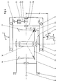
- the wheel 12 is supported with bearings 15 on the steering knuckle 11, which is pivotally pivoted about the pivot axis 10 on the axle bridge 16.
- the axle bridge 16 is connected to the vehicle 17.
- the drive shaft 18 mounted in the axle bridge 16 carries at its end a bevel gear 19 which meshes with the bevel gear 20 acting as an intermediate gear.
- the gear 20, whose axis of rotation is aligned with the pivot axis 10, meshes with a further bevel gear 21, which is mounted with the bearings 13 and 14 in the pivotable steering knuckle 11.
- the ring gear 23 of this epicyclic gear is rotatably connected to the steering knuckle 11 and the planet gears 24 are mounted on the planet gear carrier 25, which in turn is rotatably connected to the impeller 12.
- FIG. 2 in which the same parts as in FIG. 1 are provided with the same reference numerals, shows an embodiment of the device according to the invention for steering torque compensation, in which the shaft of the gear wheel 21 is directly connected via a torsionally rigid, radially and axially flexible coupling 27 without an intermediate reduction gear is connected to the impeller 12.
- two gear wheels 28 and 29 are mounted on a single shaft 30 that is aligned with the pivot axis 10 of the steering knuckle 11.
- the gear 29 meshes with the gear 19 of the drive
- the gear 28 meshes with the gear 21 of the output.
- the embodiment according to FIG. 4 differs from the embodiment according to FIG. 1 only in that the shaft of the bevel gear 21 is mounted with one of the two bearings 31, 32 in the rotating part 25 of the impeller 12.
- the embodiment according to FIG. 5 differs from the embodiment according to FIG. 1 only in that - due to the type of reduction gear used with the inner central wheel 22, the intermediate wheels 24 mounted in the steering knuckle 11 and the ring gear 23 connected to the wheel 12 - the directions of rotation of the gear 21 and the impeller 12 are in opposite directions.
- the gearwheel 20, whose axis of rotation is aligned with the pivot axis 10, is therefore arranged here in such a way that the tooth engagement of the gearwheels 20 and 21 lies above the center line of the impeller 12, so that the compensation torque caused by the tangential force F t is caused by the wheel circumferential force F u Steering torque is directed in the opposite direction.
- the amounts of steering and compensation torque are the same if equation (I) is fulfilled.
Landscapes
- Engineering & Computer Science (AREA)
- Mechanical Engineering (AREA)
- Transportation (AREA)
- Steering-Linkage Mechanisms And Four-Wheel Steering (AREA)
- Retarders (AREA)
- Gear Transmission (AREA)
- Steering Control In Accordance With Driving Conditions (AREA)
- Power Steering Mechanism (AREA)
Abstract
Description
Die Erfindung betrifft eine Vorrichtung für die Lenkmoment-Kompensation eines lenkbaren oder selbstlenkenden Rades, insbesondere für Schienenfahrzeuge, wobei dem angetriebenen oder gebremsten Rad ein der wirksamen Radumfangskraft proportionales, durch Radumfangskraft und Lenkrollhalbmesser bestimmtes Wendemoment von aussen aufgeprägt wird.The invention relates to a device for the steering torque compensation of a steerable or self-steering wheel, in particular for rail vehicles, wherein the driven or braked wheel is subjected to a turning moment which is proportional to the effective wheel circumferential force and is determined by the wheel circumferential force and the steering roller radius from the outside.
Durch Radumfangskräfte und Lenkrollhalbmesser entstehende Lenkmomente werden bisher normalerweise durch Spurstangen zwischen einander gegenüberliegenden Rädern gegeneinander geschaltet und damit in ihrer Wirkung aufgehoben. Sind jedoch (z.B. durch unterschiedliche Radumfangskräfte) die Lenkmomente an den durch die Spurstangen verbundenen Rädern nicht gleich, können die Momente nur teilweise kompensiert werden. Es wurde daher in DE-A 35 41 732 vorgeschlagen, eine bei jeder Umfangskraft wirksame Kompensation des Lenkmomentes dadurch zu erreichen, dass das Reaktionsmoment eines im Rad befindlichen Untersetzungsgetriebes über Hebel übertragen und als Kompensationsmoment genutzt wird. Das Reaktionsmoment des Getriebes ist dem Antriebs- oder Bremsmoment und folglich der Radumfangskraft stets proportional und deshalb zur Kompensation des Lenkmomentes gut geeignet. Die technische Durchführung hat jedoch erhebliche Nachteile, weil der das Reaktionsmoment führende Teil des Getriebes drehbar gelagert und das Reaktionsmoment über eine Drehmomentabstützung (z.B. ein Hebelsystem) auf den Achsträger geleitet werden muss. Ein Antrieb mit der nach DE-A 35 41 732 vorgeschlagenen Lenkmoment-Kompensation erfordert deshalb einen grösseren Bauraum und ist erheblich aufwendiger als ein Antrieb ohne eine solche.Steering torques created by wheel circumferential forces and steering roller radius have previously been normally switched against each other by tie rods between opposing wheels and their effects are thus canceled. However, if the steering torques on the wheels connected by the tie rods are not the same (eg due to different wheel circumferential forces), the torques can only be partially compensated for. It was therefore proposed in DE-A 35 41 732 to achieve effective compensation of the steering torque with any circumferential force by transferring the reaction torque of a reduction gear located in the wheel via levers and using it as a compensation torque. The reaction torque of the transmission is always proportional to the drive or braking torque and consequently the wheel circumferential force and is therefore well suited to compensating for the steering torque. The technical implementation has considerable disadvantages, however, because the part of the gearbox that carries the reaction torque must be rotatably mounted and the reaction torque must be directed to the axle support via a torque support (eg a lever system). A drive with the steering torque compensation proposed according to DE-A 35 41 732 therefore requires a larger installation space and is considerably more complex than a drive without such.
Der vorliegenden Erfindung liegt daher die Aufgabe zugrunde, die Nachteile der bekannten Vorrichtung zu vermeiden und eine Vorrichtung zur Lenkmoment-Kompensation zur schaffen, die vom Vorhandensein eines Untersetzungsgetriebes unabhängig ist, nicht mehr Bauteile be-nötigt als eine vergleichbare Konstruktion ohne Lenkmoment-Kompensation und sich auch bei kleinen Rädern verwenden lässt.The present invention is therefore based on the object of avoiding the disadvantages of the known device and of providing a device for steering torque compensation which is independent of the presence of a reduction gear and does not require more components than a comparable construction without steering torque compensation and itself can also be used on small bikes.
Die Lösung der Aufgabe besteht darin, dass die Rotationsachse eines Zahnrades eines Getriebes mit der Schwenkachse des Achsschenkels fluchtet und dieses Zahnrad mit einem weiteren Zahnrad kämmt, welches direkt oder über ein zwischengeschaltetes Getriebe, beispielsweise ein Planetengetriebe, mit dem Laufrad verbunden ist und dass die im Wälzpunkt des Zahneingriffs der beiden Zahnräder wirkende Tangentialkraft Ft mit dem Betriebswälzkreisradius rb1 des erstgenannten Zahnrads ein um die Schwenkachse wirkendes Kompensationsmoment ergibt, welches dem durch Radumfangskraft Fu und Lenkrollhalbmesser r₁ gebildetes Lenkmoment betragsmässig gleich aber entgegengesetzt gerichtet ist.The solution to the problem is that the axis of rotation of a gear of a transmission is aligned with the pivot axis of the steering knuckle and this gear meshes with another gear which is connected directly or via an intermediate gear, for example a planetary gear, to the impeller and that the Rolling point of the tooth engagement of the two gear wheels acting tangential force F t with the operating pitch circle radius r b1 of the first-mentioned gear wheel results in a compensation torque which acts around the pivot axis and which is the steering torque formed by the wheel circumferential force F u and the steering roller radius r 1 in the same amount but in the opposite direction.
Vorteilhaft können auch zwei Zahnräder auf einer einzigen, mit der Schwenkachse des Achsschenkels fluchtenden Welle angeordnet sein, von denen das eine Zahnrad mit dem Zahnrad des Abtriebs und das andere Zahnrad mit dem Zahnrad des Antriebs kämmt.Two gears can advantageously also be arranged on a single shaft aligned with the swivel axis of the steering knuckle, one of which meshes with the gear of the output and the other gear meshes with the gear of the drive.
Zweckmässig ist das im Achsschenkel angeordnete Zahnrad bei Vorhandensein eines nachgeschalteten Getriebes mit mindestens einem von mehreren Lagern im rotierenden Teil des Laufrades gelagert.The gearwheel arranged in the steering knuckle is expediently mounted in the rotating part of the impeller in the presence of a downstream gearbox with at least one of several bearings.
Der Vorteil der erfindungsgemässen Vorrichtung besteht darin, dass ihre Wirkung vom Vorhandensein eines Untersetzungsgetriebes unabhängig ist und dass dass nicht mehr Bauteile erforderlich sind als bei einer vergleichbaren Konstruktion ohne Lenkmoment-Kompensation.The advantage of the device according to the invention is that its effect is independent of the presence of a reduction gear and that no more components are required than in a comparable construction without steering torque compensation.
In den Zeichnungen sind beispielsweise Ausführungsformen der Erfindung schematisch dargestellt und zwar zeigen :
- Figur 1
- ein aus drei Kegelzahnrädern bestehendes Getriebe mit Lenkmoment-Kompensationsvorrichtung,
- Figur 2
- eine Vorrichtung gemäss Figur 1, jedoch ohne ein Untersetzungsgetriebe,
- Figur 3
- ein aus vier Kegelzahnrädern aufgebautes Getriebe mit Lenkmoment-Kompensationsvorrichtung,
- Figur 4
- eine Vorrichtung gemäss Figur 1, bei welcher das abtriebsseitige Kegelrad mit einem von zwei Lagern im rotierenden Teil des Laufrades gelagert ist,
- Figur 5
- eine Vorrichtung gemäss Figur 1, jedoch mit einem drehrichtungsumkehrenden Untersetzungsgetriebe.
- Figure 1
- a gearbox consisting of three bevel gears with a steering torque compensation device,
- Figure 2
- 2 shows a device according to FIG. 1, but without a reduction gear,
- Figure 3
- a transmission made up of four bevel gears with a steering torque compensation device,
- Figure 4
- 1, in which the bevel gear on the output side is mounted with one of two bearings in the rotating part of the impeller,
- Figure 5
- a device according to Figure 1, but with a direction-reversing reduction gear.
Nach Figur 1 ist das Rad 12 mit Lagern 15 auf dem Achsschenkel 11 gelagert, welcher um die Schwenkachse 10 schwenkbar an der Achsbrücke 16 angelenkt ist. Die Achsbrücke 16 ist mit dem Fahrzeug 17 verbunden. Die in der Achsbrücke 16 gelagerte Antriebswelle 18 trägt an ihrem Ende ein Kegelzahnrad 19, welches mit dem als Zwischenrad wirkenden Kegelzahnrad 20 kämmt. Das Zahnrad 20, dessen Rotationsachse mit der Schwenkachse 10 fluchtet, kämmt mit einem weiteren, mit den Lagern 13 und 14 im schwenkbaren Achsschenkel 11 gelagerten Kegelzahnrad 21. Auf der Welle des Zahnrades 21 befindet sich das innere Zentralrad 22 eines als Untersetzungsgetriebe wirkenden Umlaufgetriebes. Das Hohlrad 23 dieses Umlaufgetriebes ist mit dem Achsschenkel 11 drehfest verbunden und die Planetenräder 24 sind auf dem Planetenradträger 25 gelagert, der seinerseits mit dem Laufrad 12 drehfest verbunden ist.According to Figure 1, the
Die im Wälzpunkt 26 des Zahneingriffs des als Zwischenrad wirkenden Zahnrades 20 mit dem Abtriebszahnrad 21 wirkende Tangentialkraft Ft ergibt mit dem Betriebswälzkreisradius rb1 des Zahnrades 20 ein auf den schwenkbaren Achsschenkel 11 wirkendes Moment um die Schwenkachse 10. Dieses Moment ist dem von der Radumfangskraft Fu und dem Lenkrollhalbmesser r₁ gebildeten Lenkmoment entgegengesetzt gerichtet. Damit die von den Kräften Ft und Fu verursachten Momente betragsmässig gleich sind, muss die folgende Gleichung erfüllt sein :
In Gleichung (I) bezeichnet
- rb1
- den Betriebswälzkreisradius des Zahnrades 20
- rb2
- den Betriebswälzkreisradius des Zahnrades 21
- r₁
- den Lenkrollhalbmesser
- rR
- den wirksamen Radius des Laufrades 12
- i
- das Übersetzungsverhältnis der Drehzahl des Zahnrades 21 zu der Drehzahl des
Laufrades 12
- r b1
- the operating pitch circle radius of the
gear 20 - r b2
- the operating pitch circle radius of the
gear 21 - r₁
- the steering roller radius
- r R
- the effective radius of the
impeller 12 - i
- the gear ratio of the speed of the
gear 21 to the speed of theimpeller 12
Wenn Gleichung (I) erfüllt ist, ist das Laufrad 12 unabhängig vom jeweiligen Betriebszustand nach aussen von Wendemomenten um die Schwenkachse 10 vollkommen frei.If equation (I) is satisfied, the
Figur 2, in der gleiche Teile wie in Fig.1 mit gleichen Bezugszeichen versehen sind, zeigt eine Ausführungsform der erfindungsgemässen Vorrichtung zur Lenkmoment-Kompensation, bei der die Welle des Zahnrades 21 ohne einzwischengeschaltetes Untersetzungsgetriebe direkt über eine drehsteife, radial und axial nachgiebige Kupplung 27 mit dem Laufrad 12 verbunden ist. In Gleichung (I) ist bei dieser Ausführungsform der Wert i = 1 einzusetzen.FIG. 2, in which the same parts as in FIG. 1 are provided with the same reference numerals, shows an embodiment of the device according to the invention for steering torque compensation, in which the shaft of the
Nach Fig.3, in der gleiche Teile wie in Fig.1 und 2 mit gleichen Bezugszeichen versehen sind, sind zwei Zahnräder 28 und 29 auf einer einziges, mit der Schwenkachse 10 des Achsschenkels 11 fluchtenden Welle 30 gelagert. Das Zahnrad 29 kämmt mit dem Zahnrad 19 des Antriebs, das Zahnrad 28 kämmt mit dem Zahnrad 21 des Abtriebs.According to FIG. 3, in which the same parts as in FIGS. 1 and 2 are provided with the same reference numerals, two
Die Ausführung nach Fig.4 unterscheidet sich von der Ausführung nach Fig. 1 nur dadurch, dass die Welle des Kegelzahnrades 21 mit einem der beiden Lager 31, 32 im rotierenden Teil 25 des Laufrades 12 gelagert ist.The embodiment according to FIG. 4 differs from the embodiment according to FIG. 1 only in that the shaft of the
Die Ausführung nach Fig. 5 unterscheidet sich von der Ausführung nach Fig. 1 nur dadurch, dass - bedingt durch die Art des eingesetzten Untersetzungsgetriebes mit dem inneren Zentralrad 22, den im Achsschenkel 11 gelagerten Zwischenrädern 24 und dem mit dem Rad 12 verbundenen Hohlrad 23 - die Drehrichtungen des Zahnrades 21 und des Laufrades 12 gegenläufig sind. Das Zahnrad 20, dessen Rotationsachse mit der Schwenkachse 10 fluchtet, ist deshalb hier so angeordnet, dass der Zahneingriff der Zahnräder 20 und 21 oberhalb der Mittellinie des Laufrades 12 liegt, damit das von der Tangentialkraft Ft verursachte Kompensationsmoment dem von der Radumfangskraft Fu verursachten Lenkmoment entgegengesetzt gerichtet ist. Die Beträge von Lenk- und Kompensationsmoment sind gleich, wenn Gleichung (I) erfüllt ist.The embodiment according to FIG. 5 differs from the embodiment according to FIG. 1 only in that - due to the type of reduction gear used with the inner
Selbstverständlich sind innerhalb der Erfindung mehrere Variationen möglich. So ist z.B. möglich, anstelle der Kegelzahnräder miteinander kämmende Stirnzahnräder mit parallelen Rotationsachsen einzusetzen. Weiterhin können auch anstelle der Zahnräder Reibräder eingesetzt werden. In allen Fällen mu muss aber die Gleichung (I) erfüllt sein, damit das durch die Tangentialkraft Ft verursachte Kompensationsmoment dem durch die Kraft Fu verursachten Lenkmoment betragsmässig gleich ist.Of course, several variations are possible within the invention. For example, instead of the bevel gears, it is possible to use spur gears that mesh with one another and have parallel axes of rotation. Furthermore, friction wheels can also be used instead of the gears. In all cases, however, equation (I) must be satisfied so that the compensation torque caused by the tangential force F t is equal in amount to the steering torque caused by the force F u .
Claims (3)
- Steering moment compensation device for a steerable or self-steering wheel (12), particularly for rail vehicles, in which device a turning moment Proportional to the effective wheel peripheral force and determined by the wheel peripheral force and the rolling point radius of steer is imposed externally on the driven or braked wheel, characterized in that the axis of rotation of a first gearwheel (20) of a gear train is aligned with the pivoting axis (10) of the stub axle (11) and that this first gearwheel (20) engages with a further second gearwheel (21) which is connected to the running wheel (12) either directly or via an intermediate gear, for example an epicyclic gear (22-24) and that the tangential force (Ft) acting at the rolling point (26) of the two gearwheels (20 and 21), together with the operational pitch circle radius (rbl) of the first gearwheel (20), provides a compensation moment about the pivoting axis (10) of the stub axle (11) and acting on the stub axle (11), which compensation moment is equal in magnitude but opposite in sense to the turning moment determined by the wheel peripheral force (Fu) and the rolling point radius of steer (rl).
- Device according to claim 1, characterized in that two gearwheels (28 and 29) are located on a single shaft (30) aligned with the pivoting axis (10) of the stub axle (11), of which two gearwheels, one gearwheel (28) engages with the driven gearwheel (29) (sic) and the other gearwheel (29) engages with the drive gearwheel (19).
- Device according to claims 1 or 2, characterized in that if there is a subsequent gear train, the gearwheel (21) is supported by at least one (31) of a plurality of bearings (31, 32) in the rotating part (25) of the running wheel (12).
Priority Applications (1)
| Application Number | Priority Date | Filing Date | Title |
|---|---|---|---|
| AT88116345T ATE71035T1 (en) | 1987-10-12 | 1988-10-03 | DEVICE FOR STEERING TORQUE COMPENSATION OF A STEERING OR SELF-STEERING WHEEL. |
Applications Claiming Priority (2)
| Application Number | Priority Date | Filing Date | Title |
|---|---|---|---|
| DE19873734441 DE3734441A1 (en) | 1987-10-12 | 1987-10-12 | DEVICE FOR STEERING TORQUE COMPENSATION OF A STEERING OR SELF-STEERING WHEEL |
| DE3734441 | 1987-10-12 |
Publications (3)
| Publication Number | Publication Date |
|---|---|
| EP0311868A2 EP0311868A2 (en) | 1989-04-19 |
| EP0311868A3 EP0311868A3 (en) | 1989-10-25 |
| EP0311868B1 true EP0311868B1 (en) | 1992-01-02 |
Family
ID=6338132
Family Applications (1)
| Application Number | Title | Priority Date | Filing Date |
|---|---|---|---|
| EP88116345A Expired - Lifetime EP0311868B1 (en) | 1987-10-12 | 1988-10-03 | Steering moment compensation device for a steerable or a self-steering wheel |
Country Status (4)
| Country | Link |
|---|---|
| EP (1) | EP0311868B1 (en) |
| AT (1) | ATE71035T1 (en) |
| DE (2) | DE3734441A1 (en) |
| ES (1) | ES2030131T3 (en) |
Family Cites Families (5)
| Publication number | Priority date | Publication date | Assignee | Title |
|---|---|---|---|---|
| GB201921A (en) * | 1922-08-01 | 1924-05-29 | Karel Willem Gerard Johan Stof | Improvements in or relating to driving mechanism for electric rail-cars |
| DE2259035B2 (en) * | 1972-11-29 | 1979-09-20 | Licentia Patent-Verwaltungs-Gmbh, 6000 Frankfurt | Arrangement for track guidance of wheelsets |
| DE2614166C3 (en) * | 1976-04-02 | 1980-01-24 | Messerschmitt-Boelkow-Blohm Gmbh, 8000 Muenchen | Wheel set for rail vehicles |
| DE3538513A1 (en) * | 1987-04-27 | 1987-05-07 | Scheucken Heinrich | Lightweight tram car with steered, driven or idling single-wheel running gear and continuous low-level floor for single-step entry |
| DE3541732A1 (en) * | 1985-11-26 | 1987-05-27 | Duewag Ag | Steering torque compensation |
-
1987
- 1987-10-12 DE DE19873734441 patent/DE3734441A1/en active Granted
-
1988
- 1988-10-03 ES ES198888116345T patent/ES2030131T3/en not_active Expired - Lifetime
- 1988-10-03 AT AT88116345T patent/ATE71035T1/en not_active IP Right Cessation
- 1988-10-03 DE DE8888116345T patent/DE3867411D1/en not_active Expired - Fee Related
- 1988-10-03 EP EP88116345A patent/EP0311868B1/en not_active Expired - Lifetime
Also Published As
| Publication number | Publication date |
|---|---|
| DE3867411D1 (en) | 1992-02-13 |
| DE3734441C2 (en) | 1991-06-06 |
| EP0311868A3 (en) | 1989-10-25 |
| EP0311868A2 (en) | 1989-04-19 |
| DE3734441A1 (en) | 1989-04-20 |
| ATE71035T1 (en) | 1992-01-15 |
| ES2030131T3 (en) | 1992-10-16 |
Similar Documents
| Publication | Publication Date | Title |
|---|---|---|
| EP1194306B1 (en) | Wheel drive | |
| DE3602930C2 (en) | ||
| EP0180748A1 (en) | Planetary gearbox | |
| DE3200276A1 (en) | "ALL-WHEEL DRIVE FOR VEHICLES" | |
| DE69014073T2 (en) | Improvement on a drive gear. | |
| DE378413C (en) | Epicyclic gearbox | |
| DE69808136T2 (en) | DIFFERENTIAL GEAR | |
| DE3200275A1 (en) | "FOUR-WHEEL DRIVE FOR VEHICLES" | |
| EP0449862B1 (en) | Automatic gearbox for motor vehicles | |
| DE2419839C3 (en) | Planetary gear | |
| DE102014221127B4 (en) | Electric drive for a vehicle and vehicle with the electric drive | |
| EP1334295A1 (en) | Differential for the final drive of a motor vehicle | |
| EP0311868B1 (en) | Steering moment compensation device for a steerable or a self-steering wheel | |
| DE10250439A1 (en) | Power split bevel gear | |
| DE2108026A1 (en) | Axle drive for wheeled vehicles with two or more driven axles | |
| DE2939760A1 (en) | SHIP PROPELLER UNIT | |
| DE102018222004A1 (en) | Wheel hub transmission of a single wheel drive of a motor vehicle | |
| DE20212094U1 (en) | Powertrain for an all-wheel drive motor vehicle | |
| DE2361614A1 (en) | GEAR ASSEMBLY | |
| EP1199237B1 (en) | Transmission for a rail vehicle | |
| DE2000797A1 (en) | Hydrostatic transmission with internal power split | |
| DE8714904U1 (en) | Device for steering torque compensation of a steerable or self-steering wheel | |
| DE10014131A1 (en) | Drive for vehicle wheel e.g. low-platform busses etc. has drive motor to drive reduction gear pinion, meshing with ring gear for max. distance between motor and wheel axle | |
| EP0160188B1 (en) | All-wheel drive for motor vehicles | |
| DE10347581B4 (en) | portal axis |
Legal Events
| Date | Code | Title | Description |
|---|---|---|---|
| PUAI | Public reference made under article 153(3) epc to a published international application that has entered the european phase |
Free format text: ORIGINAL CODE: 0009012 |
|
| AK | Designated contracting states |
Kind code of ref document: A2 Designated state(s): AT CH DE ES FR GB IT LI NL SE |
|
| PUAL | Search report despatched |
Free format text: ORIGINAL CODE: 0009013 |
|
| AK | Designated contracting states |
Kind code of ref document: A3 Designated state(s): AT CH DE ES FR GB IT LI NL SE |
|
| 17P | Request for examination filed |
Effective date: 19900405 |
|
| 17Q | First examination report despatched |
Effective date: 19910108 |
|
| GRAA | (expected) grant |
Free format text: ORIGINAL CODE: 0009210 |
|
| AK | Designated contracting states |
Kind code of ref document: B1 Designated state(s): AT CH DE ES FR GB IT LI NL SE |
|
| PG25 | Lapsed in a contracting state [announced via postgrant information from national office to epo] |
Ref country code: IT Free format text: LAPSE BECAUSE OF FAILURE TO SUBMIT A TRANSLATION OF THE DESCRIPTION OR TO PAY THE FEE WITHIN THE PRE;WARNING: LAPSES OF ITALIAN PATENTS WITH EFFECTIVE DATE BEFORE 2007 MAY HAVE OCCURRED AT ANY TIME BEFORE 2007. THE CORRECT EFFECTIVE DATE MAY BE DIFFERENT FROM THE ONE RECORDED.SCRIBED TIME-LIMIT Effective date: 19920102 Ref country code: SE Effective date: 19920102 |
|
| REF | Corresponds to: |
Ref document number: 71035 Country of ref document: AT Date of ref document: 19920115 Kind code of ref document: T |
|
| REF | Corresponds to: |
Ref document number: 3867411 Country of ref document: DE Date of ref document: 19920213 |
|
| PG25 | Lapsed in a contracting state [announced via postgrant information from national office to epo] |
Ref country code: FR Effective date: 19920522 |
|
| GBT | Gb: translation of ep patent filed (gb section 77(6)(a)/1977) | ||
| ET | Fr: translation filed | ||
| PG25 | Lapsed in a contracting state [announced via postgrant information from national office to epo] |
Ref country code: GB Effective date: 19921003 |
|
| REG | Reference to a national code |
Ref country code: ES Ref legal event code: FG2A Ref document number: 2030131 Country of ref document: ES Kind code of ref document: T3 |
|
| PG25 | Lapsed in a contracting state [announced via postgrant information from national office to epo] |
Ref country code: CH Effective date: 19921031 Ref country code: LI Effective date: 19921031 |
|
| PLBE | No opposition filed within time limit |
Free format text: ORIGINAL CODE: 0009261 |
|
| STAA | Information on the status of an ep patent application or granted ep patent |
Free format text: STATUS: NO OPPOSITION FILED WITHIN TIME LIMIT |
|
| 26N | No opposition filed | ||
| PGFP | Annual fee paid to national office [announced via postgrant information from national office to epo] |
Ref country code: ES Payment date: 19930426 Year of fee payment: 5 |
|
| PG25 | Lapsed in a contracting state [announced via postgrant information from national office to epo] |
Ref country code: NL Effective date: 19930501 |
|
| GBPC | Gb: european patent ceased through non-payment of renewal fee |
Effective date: 19921003 |
|
| NLV4 | Nl: lapsed or anulled due to non-payment of the annual fee | ||
| REG | Reference to a national code |
Ref country code: CH Ref legal event code: PL |
|
| REG | Reference to a national code |
Ref country code: FR Ref legal event code: ST |
|
| PG25 | Lapsed in a contracting state [announced via postgrant information from national office to epo] |
Ref country code: ES Free format text: LAPSE BECAUSE OF THE APPLICANT RENOUNCES Effective date: 19931004 |
|
| PGFP | Annual fee paid to national office [announced via postgrant information from national office to epo] |
Ref country code: AT Payment date: 19970929 Year of fee payment: 10 |
|
| PGFP | Annual fee paid to national office [announced via postgrant information from national office to epo] |
Ref country code: DE Payment date: 19971023 Year of fee payment: 10 |
|
| PG25 | Lapsed in a contracting state [announced via postgrant information from national office to epo] |
Ref country code: AT Free format text: LAPSE BECAUSE OF NON-PAYMENT OF DUE FEES Effective date: 19981003 |
|
| PG25 | Lapsed in a contracting state [announced via postgrant information from national office to epo] |
Ref country code: DE Free format text: LAPSE BECAUSE OF NON-PAYMENT OF DUE FEES Effective date: 19990803 |
|
| REG | Reference to a national code |
Ref country code: ES Ref legal event code: FD2A Effective date: 19991007 |