EP0311150A1 - Ultrasonic probe for electronic sector scanning, and echoscope incorporating such a probe - Google Patents
Ultrasonic probe for electronic sector scanning, and echoscope incorporating such a probe Download PDFInfo
- Publication number
- EP0311150A1 EP0311150A1 EP88119008A EP88119008A EP0311150A1 EP 0311150 A1 EP0311150 A1 EP 0311150A1 EP 88119008 A EP88119008 A EP 88119008A EP 88119008 A EP88119008 A EP 88119008A EP 0311150 A1 EP0311150 A1 EP 0311150A1
- Authority
- EP
- European Patent Office
- Prior art keywords
- probe
- transducer elements
- group
- reception
- transmission
- Prior art date
- Legal status (The legal status is an assumption and is not a legal conclusion. Google has not performed a legal analysis and makes no representation as to the accuracy of the status listed.)
- Withdrawn
Links
Images

Classifications
-
- G—PHYSICS
- G01—MEASURING; TESTING
- G01S—RADIO DIRECTION-FINDING; RADIO NAVIGATION; DETERMINING DISTANCE OR VELOCITY BY USE OF RADIO WAVES; LOCATING OR PRESENCE-DETECTING BY USE OF THE REFLECTION OR RERADIATION OF RADIO WAVES; ANALOGOUS ARRANGEMENTS USING OTHER WAVES
- G01S15/00—Systems using the reflection or reradiation of acoustic waves, e.g. sonar systems
- G01S15/88—Sonar systems specially adapted for specific applications
- G01S15/89—Sonar systems specially adapted for specific applications for mapping or imaging
- G01S15/8906—Short-range imaging systems; Acoustic microscope systems using pulse-echo techniques
- G01S15/8909—Short-range imaging systems; Acoustic microscope systems using pulse-echo techniques using a static transducer configuration
- G01S15/8915—Short-range imaging systems; Acoustic microscope systems using pulse-echo techniques using a static transducer configuration using a transducer array
- G01S15/892—Short-range imaging systems; Acoustic microscope systems using pulse-echo techniques using a static transducer configuration using a transducer array the array being curvilinear
-
- G—PHYSICS
- G01—MEASURING; TESTING
- G01S—RADIO DIRECTION-FINDING; RADIO NAVIGATION; DETERMINING DISTANCE OR VELOCITY BY USE OF RADIO WAVES; LOCATING OR PRESENCE-DETECTING BY USE OF THE REFLECTION OR RERADIATION OF RADIO WAVES; ANALOGOUS ARRANGEMENTS USING OTHER WAVES
- G01S7/00—Details of systems according to groups G01S13/00, G01S15/00, G01S17/00
- G01S7/52—Details of systems according to groups G01S13/00, G01S15/00, G01S17/00 of systems according to group G01S15/00
- G01S7/52017—Details of systems according to groups G01S13/00, G01S15/00, G01S17/00 of systems according to group G01S15/00 particularly adapted to short-range imaging
- G01S7/52053—Display arrangements
- G01S7/52057—Cathode ray tube displays
- G01S7/5206—Two-dimensional coordinated display of distance and direction; B-scan display
- G01S7/52063—Sector scan display
-
- G—PHYSICS
- G10—MUSICAL INSTRUMENTS; ACOUSTICS
- G10K—SOUND-PRODUCING DEVICES; METHODS OR DEVICES FOR PROTECTING AGAINST, OR FOR DAMPING, NOISE OR OTHER ACOUSTIC WAVES IN GENERAL; ACOUSTICS NOT OTHERWISE PROVIDED FOR
- G10K11/00—Methods or devices for transmitting, conducting or directing sound in general; Methods or devices for protecting against, or for damping, noise or other acoustic waves in general
- G10K11/18—Methods or devices for transmitting, conducting or directing sound
- G10K11/26—Sound-focusing or directing, e.g. scanning
- G10K11/32—Sound-focusing or directing, e.g. scanning characterised by the shape of the source
-
- G—PHYSICS
- G10—MUSICAL INSTRUMENTS; ACOUSTICS
- G10K—SOUND-PRODUCING DEVICES; METHODS OR DEVICES FOR PROTECTING AGAINST, OR FOR DAMPING, NOISE OR OTHER ACOUSTIC WAVES IN GENERAL; ACOUSTICS NOT OTHERWISE PROVIDED FOR
- G10K11/00—Methods or devices for transmitting, conducting or directing sound in general; Methods or devices for protecting against, or for damping, noise or other acoustic waves in general
- G10K11/18—Methods or devices for transmitting, conducting or directing sound
- G10K11/26—Sound-focusing or directing, e.g. scanning
- G10K11/34—Sound-focusing or directing, e.g. scanning using electrical steering of transducer arrays, e.g. beam steering
- G10K11/341—Circuits therefor
- G10K11/346—Circuits therefor using phase variation
Landscapes
- Engineering & Computer Science (AREA)
- Physics & Mathematics (AREA)
- Acoustics & Sound (AREA)
- Radar, Positioning & Navigation (AREA)
- Remote Sensing (AREA)
- Multimedia (AREA)
- Computer Networks & Wireless Communication (AREA)
- General Physics & Mathematics (AREA)
- Investigating Or Analyzing Materials By The Use Of Ultrasonic Waves (AREA)
- Ultra Sonic Daignosis Equipment (AREA)
- Measurement Of Velocity Or Position Using Acoustic Or Ultrasonic Waves (AREA)
Abstract
Sonde à ultrasons et échographe à balayage sectoriel statique notamment pour image à grand angle. Selon un mode de réalisation possible, la sonde comporte plusieurs groupes (G1, G2, G3) d'éléments transducteurs (Ti) faisant entre eux des angles obtus (â) de façon à définir globalement un contour convexe de sorte que les retards nécessaires pour obtenir un balayage complet soient plus faibles qu'avec une barrette linéaire classique et donc plus faciles à maîtriser. Application à l'échographie médicale.Static sector scanning ultrasound probe and ultrasound scanner, especially for wide angle images. According to one possible embodiment, the probe comprises several groups (G1, G2, G3) of transducer elements (Ti) forming between them obtuse angles (â) so as to define a generally convex contour so that the delays necessary for to obtain a complete sweep are weaker than with a conventional linear bar and therefore easier to control. Application to medical ultrasound.
Description
L'invention concerne une sonde à ultrasons à balayage sectoriel electronique mettant en jeu la technique d'insonation connue sous le nom de "phased array" où un même groupe d'éléments transducteurs est excité à chaque séquence d'émission-réception avec des retards prédéterminés entre les éléments transducteurs du groupe. L'invention concerne aussi un échographe incorporant ce nouveau type de sonde.The invention relates to an electronic sector scanning ultrasound probe using the insonation technique known as a "phased array" in which the same group of transducer elements is excited at each transmission-reception sequence with delays. predetermined between the transducer elements of the group. The invention also relates to an ultrasound system incorporating this new type of probe.
Un échographe à balayage sectoriel électronique connu comporte une sonde incorporant un groupe d'éléments transducteurs distincts alignés suivant un segment de droite relativement court. A titre d'exemple, les dimensions de la barette d'éléments transducteurs piezo électrique sont couramment de 20 mm de long et de 15 mm de large, environ. Le nombre d'éléments transducteurs est généralement inférieur à 100 et plus couramment compris entre 30 et 70. Contrairement aux systèmes à barrettes comportant un nombre supérieur d'éléments et parmi lesquels un groupe différent d'éléments transducteurs est sélectionné à chaque séquence d'émission-réception, tous les éléments transducteurs du groupe sont sollicités à chaque séquence d'émission-réception. On excite les éléments transducteurs avec des retards prédéterminés entre eux puis on effectue la sommation des échos perçus par ces mêmes éléments, de préférence en leur appliquant la même loi de retards. A l'émission, la loi de retards conditionne à la fois l'orientation du faisceau d'ultrasons et les caractéristiques focales de ce faisceau. A la réception, la même loi de retards appliquée entre les différentes voies de traitement des signaux, avant leur sommation, crée une focalisation dynamique et privilégie la réception suivant une certaine direction. On conçoit donc que la partie électronique de ce type d'échographe est très complexe et coûteuse. En outre, il est très difficile de réaliser un balayage correct sur un secteur angulaire important. En effet, plus l'angle d'inclinaison est grand par rapport à la barette piézo électrique matérialisant le groupement d'éléments transducteurs, plus les retards mis en jeu entre les éléments doivent être importants. A titre d'exemple un faisceau dévié de 45° par rapport au plan d'émission de la barrette nécessite des retards pouvant atteindre dix microsecondes et la valeur de ces retards doit être maîtrisée avec une grande précision, de l'ordre de 20 nanosecondes. La réalisation de ces retards pose des problèmes technologiques complexes. D'autre part, on a constaté que la sensibilité d'un élément piézo électrique diminue rapidement à la réception lorsque l'angle d'incidence du faisceau correspondant augmente.A known electronic sector scanning ultrasound system includes a probe incorporating a group of separate transducer elements aligned along a relatively short line segment. By way of example, the dimensions of the bar of piezoelectric transducer elements are commonly 20 mm long and 15 mm wide, approximately. The number of transducer elements is generally less than 100 and more commonly between 30 and 70. Unlike array systems having a greater number of elements and from which a different group of transducer elements is selected at each emission sequence -reception, all the transducer elements of the group are requested at each transmission-reception sequence. The transducer elements are excited with predetermined delays between them and then the echoes perceived by these same elements are summed, preferably by applying the same law of delays to them. On transmission, the delay law conditions both the orientation of the ultrasound beam and the focal characteristics of this beam. On reception, the same delay law applied between the different signal processing channels, before their summation, creates dynamic focusing and favors reception in a certain direction. It is therefore understandable that the electronic part of this type of ultrasound system is very complex and expensive. In addition, it is very difficult to carry out a correct scan over a large angular sector. In fact, the greater the angle of inclination relative to the piezoelectric bar materializing the grouping transducer elements, the greater the delays involved between the elements. By way of example, a beam deviated by 45 ° relative to the emission plane of the bar requires delays of up to ten microseconds and the value of these delays must be controlled with great precision, of the order of 20 nanoseconds. The achievement of these delays poses complex technological problems. On the other hand, it has been found that the sensitivity of a piezoelectric element decreases rapidly on reception when the angle of incidence of the corresponding beam increases.
L'invention a pour but de résoudre ces inconvénients en proposant, d'une part, une nouvelle structure de sonde permettant de reconstituer une image à partir de balayages angulaires d'ouvertures relativement faibles et, d'autre part, un échographe incorporant une telle sonde.The invention aims to solve these drawbacks by proposing, on the one hand, a new probe structure making it possible to reconstruct an image from angular scans of relatively small apertures and, on the other hand, an ultrasound system incorporating such an probe.
Plus précisément, l'invention concerne donc une sonde à ultrasons pour un balayage sectoriel électronique comprenant au moins un alignement d'éléments transducteurs, caractérisée en ce qu'elle comporte plusieurs groupes d'éléments transducteurs respectivement alignés suivant des portions consécutives d'un contour convexe, chaque portion se distinguant d'une portion adjacente par une discontinuité et/ou un rayon de courbure différent.More specifically, the invention therefore relates to an ultrasonic probe for electronic sector scanning comprising at least one alignment of transducer elements, characterized in that it comprises several groups of transducer elements respectively aligned in consecutive portions of a contour convex, each portion being distinguished from an adjacent portion by a discontinuity and / or a different radius of curvature.
Bien entendu, le rayon de courbure d'une portion de contour donné peut être infini, ce qui signifie que les éléments transducteurs du groupe correspondant sont alignés suivant une portion de droite. Selon le mode de réalisation le plus simple, la sonde comportera donc deux groupes adjacents par exemple alignés suivant des portions de droites ou de courbes (ou une droite et une courbe) faisant entre elles un certain angle. Un autre mode de réalisation qui sera décrit en détail plus loin comportera au moins trois groupes précités d'éléments transducteurs alignés suivant des portions de droites consécutives, faisant entre elles des angles obtus égaux.Of course, the radius of curvature of a given contour portion can be infinite, which means that the transducer elements of the corresponding group are aligned along a straight portion. According to the simplest embodiment, the probe will therefore comprise two adjacent groups, for example aligned along portions of straight lines or curves (or a straight line and a curve) forming a certain angle between them. Another embodiment which will be described in detail below will include at least three aforementioned groups of transducer elements aligned along portions of consecutive lines, forming between them equal obtuse angles.
Selon un mode de réalisation particulièrement simple, la sonde comportera au moins trois groupes précités alignés suivant des portions de droite consécutives, faisant entre elles des angles obtus égaux.According to a particularly simple embodiment, the probe comprise at least three aforementioned groups aligned in consecutive straight portions, forming between them equal obtuse angles.
Ainsi, les différents groupes d'éléments transducteurs, orientés différemment, peuvent être affectés à l'insonation de secteurs angulaires adjacents dans le plan d'une coupe à imager, ces secteurs angulaires ayant des ouvertures relativement faibles (donc nécessitant des retards comparativement plus faibles) dont la juxtaposition sur un moyen de visualisation restitue une image à large champ. Il est à noter que le nombre total d'éléments transducteurs est pratiquement identique à ce qui serait nécessaire (avec des lois de retards technologiquement plus difficiles à réaliser) pour restituer une image à large champ comparable, à partir d'une barrette linéaire unique. Les dimensions de la sonde sont aussi du même ordre de grandeur (plutôt inférieures) ce qui est un critère important pour certains types d'examen.Thus, the different groups of transducer elements, oriented differently, can be assigned to the insonation of adjacent angular sectors in the plane of a section to be imaged, these angular sectors having relatively small openings (therefore requiring comparatively smaller delays ) whose juxtaposition on a display means reproduces a wide field image. It should be noted that the total number of transducer elements is practically identical to what would be necessary (with delay laws technologically more difficult to achieve) to restore an image with comparable wide field, from a single linear strip. The dimensions of the probe are also of the same order of magnitude (rather smaller) which is an important criterion for certain types of examination.
Le fait que le nombre d'éléments transducteurs n'est pas plus élevé que par le passé a d'autres conséquence sur l'électronique de traitement associée.
- Si on fait correspondre une voie d'émission-réception à chaque élément transducteur, la complexité de l'échographe est la même que par le passé, mais on peut piloter chaque groupe indépendamment et la cadence d'images peut donc être multipliée par le nombre de groupes.
- Inversement, pour une même cadence d'images, des moyens de multiplexages peu coûteux permettent de diviser le nombre de voies d'émission-réception par le nombre de groupes d'éléments transducteurs précités, ce qui se traduit par une nouvelle et importante réduction du prix de l'installation.The fact that the number of transducer elements is not higher than in the past has other consequences for the associated processing electronics.
- If we match a transmit-receive channel to each transducer element, the complexity of the ultrasound system is the same as in the past, but we can control each group independently and the frame rate can therefore be multiplied by the number of groups.
- Conversely, for the same frame rate, inexpensive multiplexing means make it possible to divide the number of transmission-reception channels by the number of groups of aforementioned transducer elements, which results in a new and significant reduction the price of the installation.
L'invention concerne également un échographe comportant une sonde à balayage sectoriel électronique, caractérisé en ce que cette sonde comporte plusieurs groupes d'éléments transducteurs alignés suivant des portions consécutives d'un contour convexe, et en ce qu'il comporte des moyens d'émission-réception pour organiser des séquences d'émission-réception à partir d'au moins un groupe d'éléments transducteurs, lesdits moyens d'émission-réception comportant un nombre de voies d'émission-réception au moins égal au nombre d'éléments transducteurs de l'un des groupes et chaque séquence mettant en jeu une loi de retards prédéterminée entre les éléments transducteurs dudit groupe, déterminant une directivité et une focalisation données à l'émission, et de préférence, une focalisation à la réception.The invention also relates to an ultrasound system comprising an electronic sector scanning probe, characterized in that this probe comprises several groups of transducer elements aligned along consecutive portions of a convex contour, and in that it comprises means for emission-reception to organize transmission-reception sequences from at least one group of transducer elements, said transmission-reception means comprising a number of transmission-reception channels at least equal to the number of transducer elements of one of the groups and each sequence involving a predetermined delay law between the transducer elements of said group, determining a directivity and a focus given on transmission, and preferably, a focus on reception.
L'invention sera mieux comprise et d'autres avantages de celle-ci apparaîtront mieux à la lumière de la description qui va suivre, donnée uniquement à titre d'exemple et faite en référence aux dessins annexés dans lesquels:
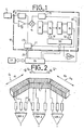
- - la figure 1 est un schéma bloc des éléments essentiels d'un échographe conforme à l'invention;
- - la figure 2 représente schématiquement en perspective une sonde conforme au principe de l'invention, et, sous forme de schéma- bloc, les éléments essentiels d'un échographe équipé d'une telle sonde ;
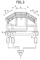
- - la figure 3 est une vue analogue à la figure 2, illustant une variante d'exécution ;
- - la figure 4 est une vue analogue à la figure 2, illustrant une autre variante d'exécution ;
- - la figure 5 est une vue schématique de profil d'une sonde à ultrasons conforme à l'invention, utilisable en lieu et place de la sonde des figures 2 à 4;
- - la figure 6 est une vue schématique de profil d'une autre sonde à ultrasons conforme à l'invention utilisable en lieu et place des sondes représentées sur les figures 2 à 5.
- - Figure 1 is a block diagram of the essential elements of an ultrasound system according to the invention;
- - Figure 2 shows schematically in perspective a probe according to the principle of the invention, and, in the form of a diagram, the essential elements of an ultrasound system equipped with such a probe;
- - Figure 3 is a view similar to Figure 2, illustrating an alternative embodiment;
- - Figure 4 is a view similar to Figure 2, illustrating another alternative embodiment;
- - Figure 5 is a schematic profile view of an ultrasonic probe according to the invention, usable instead of the probe of Figures 2 to 4;
- FIG. 6 is a schematic profile view of another ultrasonic probe according to the invention which can be used in place of the probes shown in FIGS. 2 to 5.
La figure 1 représente partiellement un agencement possible des moyens d'émission-réception d'un échographe utilisable avec une sonde à ultrasons selon la définition qui précède et le schéma montre plus particulièrement une voie d'emission-réception 10 associée à l'un des éléments transducteurs piézo électrique Ti de l'un des groupes constituant la sonde. Cet élément transducteur est connecté à un émetteur 11, connu en soi, chargé de lui transmettre, à chaque tir, une impulsion ultrasonore à la fréquence choisie. Il est aussi relié à un amplificateur 12 chargé d'amplifier les échos reçus ultérieurement par ce même transducteur. Par ailleurs, un moyen de mise en forme 13 (trigger par exemple) d'une impulsion de commande et reliée à l'entrée d'un sommateur 14 qui reçoit aussi sur son autre entrée le signal de sortie de l'amplificateur 12. La sortie du sommateur 14 est reliée à l'entrée d'une première ligne à retards 15 dont les sorties sont respectivement reliées aux entrées d'un premier multiplexeur 16. La sortie de ce dernier est reliée à l'entreé d'une deuxième ligne à retards 18 dont les sorties sont respectivement reliées aux entrées d'un second multiplexeur 19. Les retards "disponibles" aux sorties des lignes à retards 15 et 18 diffèrent d'un ordre de grandeur, de sorte qu'on peut obtenir n'importe quel retard (dans la gamme des retards nécessaires pour obtenir un balayage sectoriel souhaité) et avec la précision requise, par l'adressage des multiplexeurs 16 et 19, sélectionnant chacun une sortie de la ligne à retards correpondante. La sortie du multiplexeur 19 est connectée, d'une part, à une entrée d'un amplificateur-sommateur SOM, recevant sur d'autres entrées les signaux retardés en provenance d'autres voies d'émission-réception analogues et, d'autre part, à l'entrée de déclenchement 22 d'un générateur d'impulsions 23 chargé d'élaborer à chaque tir une impulsion d'excitation de l'émetteur 11, retardée d'un temps voulu par rapport à l'impulsion délivrée par les moyens de mise en forme 13, ce temps étant déterminé par l'état des multiplexeurs 16 et 19. Le logiciel de commande détermine la durée de l'impulsion d'excitation par une liaison de commande 24 entre le microprocesseur-séquenceur 26 et le générateur 23. Ce microproceseur-séquenceur 26 et une mémoire-programme 27 (du type PROM) associée constituent l'essentiel du logiciel de commande des différentes voies 10. Le microprocesseur commande ainsi un générateur d'adresse 30 qui pilote les deux multiplexeurs 16 et 19 de chaque voie (liaisons d'adressage 31 et 32). Le même microprocesseur est couplé à la mémoire 27 pour sélectionner dans celle-ci la lecture des instructions correspondant à un séquencement donné résultant de la combinaison des paramètres choisis par l'opérateur, notamment la fréquence des ultrasons. En fonction de ces paramètres, le processeur organise la lecture d'un certains nombres d'instructions de la mémoire-programme, régissant le cadencement des tirs d'ultrasons, leurs orientations (c'est-à-dire les lois de retards correspondantes) pour déterminer le balayage sectoriel électronique, les temps d'attente entre tirs, ect...FIG. 1 partially represents a possible arrangement of the transmission-reception means of an ultrasound system usable with an ultrasound probe according to the above definition and the diagram shows more particularly a transmission-
Pour l'excitation d'un émetteur 11, le processeur 26 émet un ordre de tir transmis par le fil de liaison 35 au moyen de mise en forme 13 et cet ordre est retardé en fonction du positionnement préalable des multiplexeurs 16 et 19 de la voie d'émission-réception 10 correspondante. Cet ordre déclenche le générateur d'impulsions 23 qui excite l'émetteur 11 pendant un intervalle de temps contrôlé par le logiciel de commande. A la réception, les échos captés par le même élément transducteur Ti sont appliqués à l'entrée de l'amplificateur 12 et dirigés vers l'ensemble des lignes à retards 15, 18, pour y subir les mêmes retards avant d'être appliqués à l'entrée correspondante de l'amplificateur-sommateur SOM, réalisant ainsi une focalisation à la réception. Les signaux de sortie de l'amplicateur-sommateur SOM sont traités (notamment fenêtrés) avant d'être utilisés en tant que signaux vidéo d'un récepteur de télévision sur lequel l'image est reconstituée ligne par ligne en plusieurs secteurs angulaires adjacents correspondant au nombre de groupes d'éléments transducteurs définis dans la sonde.For the excitation of a transmitter 11, the
La figure 2 illustre un mode de réalisation possible d'une sonde à ultrasons selon l'invention, prévu pour fonctionner avec le système de la figure 1. Selon l'exemple, la sonde comprend trois groupes G1, G2 et G3 d'éléments transducteurs Ti alignés suivant des portions consécutives d'un contour convexe constitué ici de portions de droite consécutives d1, d2 et d3, faisant entre elles de angles obtus à égaux.FIG. 2 illustrates a possible embodiment of an ultrasonic probe according to the invention, designed to operate with the system of FIG. 1. According to the example, the probe comprises three groups G1, G2 and G3 of transducer elements T i aligned along consecutive portions of a convex contour formed here of consecutive straight portions d1, d2 and d3, forming obtuse angles between them.
Dans l'exemple de la figure 2, chaque groupe G1, G2 ou G3 comporte le même nombre d'éléments transducteurs et chaque élément transducteur Ti est couplé à une voie d'émission-réception 10 conforme à la figure 1. Cependant, les sorties des voies correspondant aux éléments de chaque groupe sont reliées respectivement aux entrées de trois amplificateurs-sommateurs SOM₁, SOM₂, et SOM₃, de façon que les signaux de sortie de ces trois amplificateurs puissent être utilisés simultanément. Dans ce mode de réalisation, les moyens de commande des voies d'émission-réception (c'est-à-dire essentiellement le processeur 26 et la mémoire-programme 27) sont agencés et programmés pour engendrer sensiblement simultanément une séquence d'émission-réception dans chaque groupe. Autrement dit, le système est prévu pour engendrer trois tirs d'ultrasons simultanément, chaque tir mettant en oeuvre tous les éléments d'un groupe G1, G2, G3 en associant chaque fois à chaque groupe une loi de retards prédéterminée, définissant à la fois les caractéristiques focales du faisceau d'ultrasons émis et son orientation par rapport à la surface émissive du group correspondant. Les signaux recueillis par les éléments transducteurs de chaque groupe sont retardés les uns par rapport aux autres, par application des mêmes lois de retards, avant d'être additionnés par l'amplificateur-sommateur SOM1, SOM2 ou SOM3 correspondant. Les signaux de sortie de ces amplificateurs sont traités de façon classique pour élaborer trois signaux vidéo distincts appliqués sensiblement simultanément à un moniteur de télévision (non représenté) pour moduler trois lignes de balayage s'inscrivant respectivement dans trois secteurs adjacents de l'image. On conçoit que la cadence des images a été multipliée par le nombre de groupes sans augmenter sensiblement la complexité des circuits électroniques associés puisque le nombre d'éléments transducteurs est approximativement égal à celui d'une barrette linéaire fonctionnant en "phase array". A titre d'exemple, une telle barrette linéaire classique nécessite 64 éléments transducteurs pour balayer électroniquement un secteur angulaire de 90°, avec des retards importants pour certains éléments transducteurs. Avec le système de la figure 1, le même secteur angulaire est balayé trois fois plus rapidement par association de trois secteurs angulaires adjacents de 30° balayés, chacun, par un groupe G1, G2 ou G3 de 22 éléments transducteurs (soit un total de 66 voies d'émission-réception 10). Les lois de retards concernant chaque groupe mettent en oeuvre des valeurs de retards beaucoup plus faibles donc des lignes à retards plus faciles à construire avec la précision requise et par conséquent moins coûteuses.In the example in Figure 2, each group G1, G2 or G3 comprises the same number of transducer elements and each transducer element T i is coupled to a transmission-
Avec le mode de réalisation de la figure 2, on peut en particulier obtenir une image de grande ouverture angulaire. On peut en effet affecter à chaque groupe un balayage de 45° soit une ouverture totale de 135°. Si on choisit un pas inter-éléments égal à la longueur d'onde des ultrasons et 32 éléments par groupes, la largeur d'un groupe et de 16 mm pour une fréquence de fonctionnement de 3 MHz et l'ensemble de la surface émettrice de la sonde s'inscrit dans un rayon moyen de 22 mm. L'échographe associé comporte bien entendu 96 voies d'émission-réception. Pour éviter ou limiter les interférences entre les échos provenant de tirs simultanés effectués à partir des trois groupes, il est avantageux de choisir les lois de retards pour que les directions des trois tirs fassent toujours des angles de 45° les unes par rapport aux autres.With the embodiment of Figure 2, one can in particular obtain an image of large angular opening. We can indeed assign to each group a scan of 45 ° or a total opening of 135 °. If an inter-element pitch equal to the wavelength of the ultrasound and 32 elements per group is chosen, the width of a group is 16 mm for an operating frequency of 3 MHz and the entire emitting surface of the probe falls within an average radius of 22 mm. The associated ultrasound system of course comprises 96 transmission-reception channels. To avoid or limit the interference between the echoes coming from simultaneous shots made from the three groups, it is advantageous to choose the delay laws so that the directions of the three shots always make angles of 45 ° with respect to each other.
La figure 3 illustre un autre mode de réalisation pour lequel la cadence des images est la même que dans un système classique mais avec environ trois fois moins de circuits électroniques de traitement. La sonde proprement dite est la même que précédemment, c'est-à-dire que chaque groupe G1, G2 et G3 comporte le même nombre d'éléments transducteurs. En revanche les moyens d'émission-réception ne comportent qu'un nombre de voies d'émission-réception 10 égal au nombre d'éléments transducteurs d'un groupe tandis que des moyens de commutation séquentielle, sous la forme d'un multiplexeur 35, sont intercalés entre les groups G1, G2 et G3 et les voies d'émission-réception 10 (au nombre de 22 seulement dans l'exemple décrit, les sorties de signal de ces voies étant reliées à un unique amplificateur- sommateur SOM) pour interconnecter cycliquement et dans un ordre donné, les éléments transducteurs Ti des groupes et lesdites voies d'émission-réception 10. Plus précisément, le multiplexeur 35 est par exemple constitué d'une pluralité de portes analogiques connectées de façon à comporter trois entrées pour une sortie. Ces entrées sont interconnectées à la sonde de façon à regrouper les fils de sortie des éléments transducteurs homologues de chaque groupe vers la même sortie de multiplexage reliée à une même voie d'émission-réception 10. Le processeur 26 et la mémoire 27 pilotent, par exemple, le multiplexeur de la façon suivante. Pendant une première phase, tous les éléments du groupe G1 sont connectés aux voies d'émission-réception 10 pendant tout le temps des séquences d'émission-réception assurant un premier balayage d'un secteur de 30°. Puis le groupe G2 est substitué au groupe G1 par commutation du multiplexeur et les éléments transducteurs du groupe G2 sont reliés aux voies d'émission-réception pendant le temps d'un second balayage d'un secteur de 30° adjacent au précédent. Enfin, l'ensemble des éléments du groupe G3 est raccordé aux mêmes voies d'émission-réception pour le temps d'un troisième balayage d'un secteur de 30° adjacent.FIG. 3 illustrates another embodiment for which the frame rate is the same as in a conventional system but with approximately three times less electronic processing circuits. The actual probe is the same as before, that is to say that each group G1, G2 and G3 has the same number of transducer elements. On the other hand, the transceiver means comprise only a number of
D'autres variantes sont possibles, comme par exemple celles de la figure 4 où la sonde a été modifiée pour que les deux groupes latéraux G1 et G3 situés symétriquement de part et d'autre d'un groupe central G2 comportent chacun un nombre d'éléments transducteurs égal à la moitié du nombre d'éléments transducteurs dudit groupe central. Cette configuration présente certains avantages lorsqu'on désire que la zone centrale de l'image soit de très bonne qualité tout en conservant un champ angulaire important, les zones latérales servant alors surtout au repèrage. A titre d'exemple, le groupe central G2 peut couvrir un champs angulaire de 30° seulement et comporter 64 éléments transducteurs tandis que les groupes latéraux G1 et G3 peuvent couvrir un champ angulaire de 45° chacun mais ne comporter que 32 éléments par groupe. Des moyens de commutation séquentielle, sous forme d'un multiplexeur 36, sont intercalés entre la sonde et les moyens d'émission-réception de l'échographe, lesquels comportent alors autant de voies d'émission-réception 10 que le groupe central G2 comporte d'éléments transducteurs Ti. Ce multiplexeur 36 comporte deux entrées pour une sortie par unité de commutation. Les entrées sont reliées à la sonde pour connecter à tour de rôle et cycliquement les fils de sortie des éléments transducteurs du groupe central G2 aux différentes voies d'émission-réception 10 puis les fils de sortie des éléments transducteurs des groupes latéraux G1 et G3 avec ces mêmes voies d'émission-réception 10. Les commutations successives du multiplexeur sont contrôlées par le logiciel de commande de l'échographe comportant essentiellement le processeur 26 et la mémoire-programme 27.Other variants are possible, such as those of FIG. 4 where the probe has been modified so that the two lateral groups G1 and G3 located symmetrically on either side of a central group G2 each have a number of transducer elements equal to half the number of transducer elements of said central group. This configuration has certain advantages when it is desired that the central zone of the image be of very good quality while retaining a large angular field, the lateral zones then being used mainly for tracking. For example, the central group G2 can cover an angular field of only 30 ° and have 64 transducer elements while the lateral groups G1 and G3 can cover an angular field of 45 ° each but have only 32 elements per group. Sequential switching means, in the form of a
La figure 5 montre schématiquement et de profil une sonde analogue à celle de la figure 2 dans laquelle les trois faces émissives des groupes G1, G2 et G3 sont enrobées d'une couche 40 de matériau, par exemple un matériau élastomètre, matérialisant une surface externe convexe continue de rayon de courbure constant dans le plan de la région à imager, c'est-à-dire le plan du dessin. Cette particularité est applicable à toutes les sondes décrites ci-dessus. On peut aussi modifier la sonde conformément à la représentation de la figure 6 dans laquelle elle comporte un groupe central G2 d'éléments transducteurs alignés suivant une portion de droite et deux groupes latéraux G1 et G3 dans lesquels les éléments transducteurs sont disposés suivant des portions de courbe et, plus précisément ici, suivant des arcs d'un cercle commun de centre O. Bien entendu, une couche de matériau élastomère 40a peut être disposée à la surface du groupe central G2. Dans ce cas, la surface externe convexe de la couche de matériau élastomère matérialise une surface extérieure convexe de rayons de courbure constante et de centre O, se raccordant de façon continue aux surfaces émissives courbes des groupes G1 et G2. La matériau élastomère ainsi disposé a un effet de "lentille" procurant une focalisation moyenne dans la direction perpendiculaire au plan de l'image. La configuration inverse de celle de la figure 6 peut aussi donner de bons résultats. Dans ce cas, les deux groupes latéraux G1, G3 auraient leurs éléments transducteurs disposés suivant des portions de droites et le groupe central G2 aurait ses éléments disposés suivant une portion de courbe, par exemple un arc de cercle, le matériau élastomère mentionné ci-dessus recouvrant les surfaces émissives des éléments transducteurs des groupes G1 et G3.FIG. 5 schematically shows in profile a probe similar to that of FIG. 2 in which the three emissive faces of the groups G1, G2 and G3 are coated with a
Claims (3)
Applications Claiming Priority (2)
| Application Number | Priority Date | Filing Date | Title |
|---|---|---|---|
| FR8414708A FR2570837B1 (en) | 1984-09-25 | 1984-09-25 | ULTRASOUND PROBE FOR ELECTRONIC SECTORAL SCANNING AND ECHOGRAPH INCORPORATING SUCH A PROBE |
| FR8414708 | 1984-09-25 |
Related Parent Applications (1)
| Application Number | Title | Priority Date | Filing Date |
|---|---|---|---|
| EP85401859.5 Division | 1985-09-24 |
Publications (1)
| Publication Number | Publication Date |
|---|---|
| EP0311150A1 true EP0311150A1 (en) | 1989-04-12 |
Family
ID=9308049
Family Applications (2)
| Application Number | Title | Priority Date | Filing Date |
|---|---|---|---|
| EP88119008A Withdrawn EP0311150A1 (en) | 1984-09-25 | 1985-09-24 | Ultrasonic probe for electronic sector scanning, and echoscope incorporating such a probe |
| EP85401859A Withdrawn EP0177407A1 (en) | 1984-09-25 | 1985-09-24 | Ultrasonic probe for electronic sector scanning, and echoscope incorporating such a probe |
Family Applications After (1)
| Application Number | Title | Priority Date | Filing Date |
|---|---|---|---|
| EP85401859A Withdrawn EP0177407A1 (en) | 1984-09-25 | 1985-09-24 | Ultrasonic probe for electronic sector scanning, and echoscope incorporating such a probe |
Country Status (3)
| Country | Link |
|---|---|
| US (1) | US4694700A (en) |
| EP (2) | EP0311150A1 (en) |
| FR (1) | FR2570837B1 (en) |
Cited By (2)
| Publication number | Priority date | Publication date | Assignee | Title |
|---|---|---|---|---|
| FR2836556A1 (en) * | 2002-02-22 | 2003-08-29 | Marais Atel Du | Device for capture and reproduction of inert or living 3-D shapes comprises ultrasonic sensors that can be moved on an arm around the object in question with measurements recorded and processed using appropriate software |
| CN105283913A (en) * | 2013-02-28 | 2016-01-27 | 通用电气公司 | Delta delay approach for ultrasound beamforming on an ASIC |
Families Citing this family (12)
| Publication number | Priority date | Publication date | Assignee | Title |
|---|---|---|---|---|
| US4831601A (en) * | 1986-10-31 | 1989-05-16 | Siemens Aktiengesellschaft | Apparatus for transmitting and receiving ultrasonic signals |
| US4888720A (en) * | 1987-12-07 | 1989-12-19 | Fryer Glenn E | Tunnel measuring apparatus and method |
| FR2628539B1 (en) * | 1988-03-11 | 1991-12-20 | Cgr Ultrasonic | PROBE, IMAGING DEVICE USING SUCH A PROBE AND METHOD USING SUCH A DEVICE |
| US5078147A (en) * | 1990-01-25 | 1992-01-07 | Vivo Corporation | Method of noninvasive ultrasonic detection of nerve root inflammation |
| US7497828B1 (en) * | 1992-01-10 | 2009-03-03 | Wilk Ultrasound Of Canada, Inc. | Ultrasonic medical device and associated method |
| US5337289A (en) * | 1993-07-16 | 1994-08-09 | The United States Of America As Represented By The Department Of Energy | Phased-array ultrasonic surface contour mapping system and method for solids hoppers and the like |
| US8162859B2 (en) * | 2005-06-09 | 2012-04-24 | General Patent , LLC | Shock wave treatment device and method of use |
| EP1736799B8 (en) * | 2005-06-16 | 2013-05-29 | Kabushiki Kaisha Toshiba | Ultrasonic transmission/reception condition optimization method, corresponding program, and ultrasonic diagnostic apparatus |
| KR20080093281A (en) * | 2007-04-16 | 2008-10-21 | 주식회사 메디슨 | Ultrasound diagnostic probe |
| EP3103396B1 (en) * | 2015-06-10 | 2018-10-24 | Helmholtz Zentrum München Deutsches Forschungszentrum für Gesundheit und Umwelt GmbH | Device and method for hybrid optoacoustic tomography and ultrasonography |
| WO2017106834A1 (en) * | 2015-12-18 | 2017-06-22 | Ursus Medical, Llc | Ultrasound beamforming system and method with reconfigurable aperture |
| DE102019106427B4 (en) * | 2019-03-13 | 2022-04-28 | Bundesrepublik Deutschland, vertreten durch den Bundesminister für Wirtschaft und Energie, dieser vertreten durch den Präsidenten der Bundesanstalt für Materialforschung und –prüfung (BAM) | Transducer and transducer arrangement for ultrasonic probe systems, ultrasonic probe system and test methods |
Citations (4)
| Publication number | Priority date | Publication date | Assignee | Title |
|---|---|---|---|---|
| GB2079102A (en) * | 1980-06-27 | 1982-01-13 | Matsushita Electric Ind Co Ltd | Arc scan transducer array having a diverging lens |
| US4344327A (en) * | 1979-12-28 | 1982-08-17 | Aloka Co., Ltd. | Electronic scanning ultrasonic diagnostic system |
| US4409982A (en) * | 1980-10-20 | 1983-10-18 | Picker Corporation | Ultrasonic step scanning utilizing curvilinear transducer array |
| US4462092A (en) * | 1980-05-15 | 1984-07-24 | Matsushita Electric Industrial Company, Limited | Arc scan ultrasonic transducer array |
Family Cites Families (10)
| Publication number | Priority date | Publication date | Assignee | Title |
|---|---|---|---|---|
| IT987930B (en) * | 1972-11-02 | 1975-03-20 | Cecchettini Giancarlo | APPARATUS FOR GYMNASTICS |
| DK134499B (en) * | 1974-11-19 | 1976-11-15 | Akad Tekn Videnskaber | Apparatus for providing an ultrasound image for use in measuring the distribution of meat and fat on biological material. |
| CA1093674A (en) * | 1975-10-13 | 1981-01-13 | George Kossoff | Ultrasonic beam scanning |
| FR2332531A1 (en) * | 1975-11-24 | 1977-06-17 | Commissariat Energie Atomique | ULTRA-SOUND CAMERA |
| DE2657163A1 (en) * | 1976-12-17 | 1978-06-22 | Hugo Werner Prof Dr Buschmann | Compact ultrasonic scanner with image memory store - operates with chain of transducers subjected to mechanical oscillation |
| US4200858A (en) * | 1976-12-28 | 1980-04-29 | Canon Kabushiki Kaisha | Acoustic wave scanning apparatus |
| DE2711098C3 (en) * | 1977-03-14 | 1980-04-10 | Siemens Ag, 1000 Berlin Und 8000 Muenchen | Device for examining bodies by means of ultrasound scanning |
| US4276779A (en) * | 1979-03-29 | 1981-07-07 | Raytheon Company | Dynamically focussed array |
| JPS56155874A (en) * | 1980-05-06 | 1981-12-02 | Matsushita Electric Ind Co Ltd | Ultrasonic beam scanner |
| EP0134346B1 (en) * | 1983-08-25 | 1989-05-31 | Analogic Corporation | Ultrasonic transducers |
-
1984
- 1984-09-25 FR FR8414708A patent/FR2570837B1/en not_active Expired
-
1985
- 1985-09-24 EP EP88119008A patent/EP0311150A1/en not_active Withdrawn
- 1985-09-24 EP EP85401859A patent/EP0177407A1/en not_active Withdrawn
- 1985-09-25 US US06/779,855 patent/US4694700A/en not_active Expired - Fee Related
Patent Citations (5)
| Publication number | Priority date | Publication date | Assignee | Title |
|---|---|---|---|---|
| US4344327A (en) * | 1979-12-28 | 1982-08-17 | Aloka Co., Ltd. | Electronic scanning ultrasonic diagnostic system |
| US4344327B1 (en) * | 1979-12-28 | 1994-05-03 | Aloka Co Ltd | Electronic scanning ultrasonic diagnostic system |
| US4462092A (en) * | 1980-05-15 | 1984-07-24 | Matsushita Electric Industrial Company, Limited | Arc scan ultrasonic transducer array |
| GB2079102A (en) * | 1980-06-27 | 1982-01-13 | Matsushita Electric Ind Co Ltd | Arc scan transducer array having a diverging lens |
| US4409982A (en) * | 1980-10-20 | 1983-10-18 | Picker Corporation | Ultrasonic step scanning utilizing curvilinear transducer array |
Cited By (3)
| Publication number | Priority date | Publication date | Assignee | Title |
|---|---|---|---|---|
| FR2836556A1 (en) * | 2002-02-22 | 2003-08-29 | Marais Atel Du | Device for capture and reproduction of inert or living 3-D shapes comprises ultrasonic sensors that can be moved on an arm around the object in question with measurements recorded and processed using appropriate software |
| CN105283913A (en) * | 2013-02-28 | 2016-01-27 | 通用电气公司 | Delta delay approach for ultrasound beamforming on an ASIC |
| CN105283913B (en) * | 2013-02-28 | 2019-09-24 | 通用电气公司 | Delta related method thereof on ASIC for ultrasonic beam forming |
Also Published As
| Publication number | Publication date |
|---|---|
| FR2570837B1 (en) | 1987-11-20 |
| EP0177407A1 (en) | 1986-04-09 |
| US4694700A (en) | 1987-09-22 |
| FR2570837A1 (en) | 1986-03-28 |
Similar Documents
| Publication | Publication Date | Title |
|---|---|---|
| EP0150634B1 (en) | Transducer for ultrasonic echography provided with an array of elements forming a convex surface | |
| EP0311150A1 (en) | Ultrasonic probe for electronic sector scanning, and echoscope incorporating such a probe | |
| EP0543445B1 (en) | Examination device for media by means of ultrasonic echography | |
| EP0119911B1 (en) | Method of ultrasonic imaging using a linear array of transducer elements | |
| EP0591061B1 (en) | Method and device for acoustic examination with time reversal | |
| EP0459583B1 (en) | Ultrasonic echograph with phase aberration adaptive correction | |
| FR2763166A1 (en) | Imaging system using a network of ultra-sonic transducers. | |
| FR2485738A1 (en) | TRANSDUCER ARRAY FOR ARC SCANNING COMPRISING A DIVERGING LENS | |
| EP0383650A1 (en) | Process and apparatus for locating and focusing waves | |
| FR2763699A1 (en) | OPTOELECTRONIC DETECTOR | |
| CA2234465C (en) | Procedure and device for processing signals representative of waves reflected, transmitted or refracted by a 3-dimensional structure in order to explore and analyse the structure | |
| EP0733408B1 (en) | Ultrasonic sensor and detection method using such a sensor | |
| FR2467413A1 (en) | METHOD AND DEVICE FOR EXAMINING USING ULTRASONIC BEAMS | |
| EP0106418B1 (en) | Apparatus for examining media by ultrasonic echography | |
| EP0069677B1 (en) | Device for ultrasonic echography to scan sectorially | |
| WO2002035254A1 (en) | Method, system and probe for obtaining images | |
| EP0133135A2 (en) | Ultrasonic search unit with several transducers of different dimensions | |
| EP0040566B1 (en) | Dynamically-focused sector-scan imaging unit | |
| FR2562676A1 (en) | DEVICE FOR PROCESSING MODULAR SIGNALS RECEIVED BY A SONAR SYSTEM | |
| FR2692999A1 (en) | Echography probe for medical use - Has normal and zoom modes of operation using micro detectors and parallel transducers connected to channel | |
| EP0054045B1 (en) | Receiver for a multi-element ultrasonic probe echograph | |
| CA1260602A (en) | Method to improve the reproduction of images generated by a lateral sonar and device implementing said method | |
| FR2508665A1 (en) | Dynamic medical ultrasonic scanner for moving body - has ultrasonic bursts on focal zones determined by phase delay law and immediately succeeding data acquisition | |
| FR2535075A1 (en) | Apparatus for the examination of media by ultrasonic echography | |
| EP0286473B1 (en) | Apparatus and proceeding for the digital image processing |
Legal Events
| Date | Code | Title | Description |
|---|---|---|---|
| PUAI | Public reference made under article 153(3) epc to a published international application that has entered the european phase |
Free format text: ORIGINAL CODE: 0009012 |
|
| AC | Divisional application: reference to earlier application |
Ref document number: 177407 Country of ref document: EP |
|
| AK | Designated contracting states |
Kind code of ref document: A1 Designated state(s): DE GB IT NL |
|
| 17P | Request for examination filed |
Effective date: 19890503 |
|
| 17Q | First examination report despatched |
Effective date: 19911031 |
|
| STAA | Information on the status of an ep patent application or granted ep patent |
Free format text: STATUS: THE APPLICATION IS DEEMED TO BE WITHDRAWN |
|
| 18D | Application deemed to be withdrawn |
Effective date: 19920311 |