EP0310857A2 - Thread-changing device, especialy for knitting machines - Google Patents
Thread-changing device, especialy for knitting machines Download PDFInfo
- Publication number
- EP0310857A2 EP0310857A2 EP88115433A EP88115433A EP0310857A2 EP 0310857 A2 EP0310857 A2 EP 0310857A2 EP 88115433 A EP88115433 A EP 88115433A EP 88115433 A EP88115433 A EP 88115433A EP 0310857 A2 EP0310857 A2 EP 0310857A2
- Authority
- EP
- European Patent Office
- Prior art keywords
- thread
- loop
- changing device
- clamping hook
- new
- Prior art date
- Legal status (The legal status is an assumption and is not a legal conclusion. Google has not performed a legal analysis and makes no representation as to the accuracy of the status listed.)
- Granted
Links
- 238000009940 knitting Methods 0.000 title claims description 5
- 230000015572 biosynthetic process Effects 0.000 claims abstract description 25
- 238000004804 winding Methods 0.000 claims description 66
- 238000000034 method Methods 0.000 claims description 13
- 210000000056 organ Anatomy 0.000 claims description 5
- 230000003213 activating effect Effects 0.000 claims description 4
- 238000007664 blowing Methods 0.000 claims description 4
- 238000004140 cleaning Methods 0.000 claims 1
- 239000010437 gem Substances 0.000 claims 1
- 238000013022 venting Methods 0.000 claims 1
- 230000008859 change Effects 0.000 abstract description 2
- 238000010586 diagram Methods 0.000 description 11
- 238000012545 processing Methods 0.000 description 11
- 230000008569 process Effects 0.000 description 9
- 230000008878 coupling Effects 0.000 description 3
- 238000010168 coupling process Methods 0.000 description 3
- 238000005859 coupling reaction Methods 0.000 description 3
- 230000007246 mechanism Effects 0.000 description 3
- 238000002360 preparation method Methods 0.000 description 3
- 238000011144 upstream manufacturing Methods 0.000 description 3
- 230000008901 benefit Effects 0.000 description 2
- 230000000694 effects Effects 0.000 description 2
- 230000001960 triggered effect Effects 0.000 description 2
- 230000000903 blocking effect Effects 0.000 description 1
- 238000013461 design Methods 0.000 description 1
- 238000011161 development Methods 0.000 description 1
- 239000004744 fabric Substances 0.000 description 1
- 238000007654 immersion Methods 0.000 description 1
- 230000009191 jumping Effects 0.000 description 1
- 238000012544 monitoring process Methods 0.000 description 1
- 238000003825 pressing Methods 0.000 description 1
- 230000001681 protective effect Effects 0.000 description 1
- 230000001105 regulatory effect Effects 0.000 description 1
- 239000004753 textile Substances 0.000 description 1
- 238000009966 trimming Methods 0.000 description 1
Images


Classifications
-
- D—TEXTILES; PAPER
- D04—BRAIDING; LACE-MAKING; KNITTING; TRIMMINGS; NON-WOVEN FABRICS
- D04B—KNITTING
- D04B15/00—Details of, or auxiliary devices incorporated in, weft knitting machines, restricted to machines of this kind
- D04B15/38—Devices for supplying, feeding, or guiding threads to needles
- D04B15/48—Thread-feeding devices
-
- D—TEXTILES; PAPER
- D04—BRAIDING; LACE-MAKING; KNITTING; TRIMMINGS; NON-WOVEN FABRICS
- D04B—KNITTING
- D04B15/00—Details of, or auxiliary devices incorporated in, weft knitting machines, restricted to machines of this kind
- D04B15/38—Devices for supplying, feeding, or guiding threads to needles
- D04B15/54—Thread guides
- D04B15/58—Thread guides for circular knitting machines; Thread-changing devices
- D04B15/62—Thread guides for circular knitting machines; Thread-changing devices with thread knotters
-
- B—PERFORMING OPERATIONS; TRANSPORTING
- B65—CONVEYING; PACKING; STORING; HANDLING THIN OR FILAMENTARY MATERIAL
- B65H—HANDLING THIN OR FILAMENTARY MATERIAL, e.g. SHEETS, WEBS, CABLES
- B65H69/00—Methods of, or devices for, interconnecting successive lengths of material; Knot-tying devices ;Control of the correct working of the interconnecting device
- B65H69/04—Methods of, or devices for, interconnecting successive lengths of material; Knot-tying devices ;Control of the correct working of the interconnecting device by knotting
-
- D—TEXTILES; PAPER
- D04—BRAIDING; LACE-MAKING; KNITTING; TRIMMINGS; NON-WOVEN FABRICS
- D04B—KNITTING
- D04B35/00—Details of, or auxiliary devices incorporated in, knitting machines, not otherwise provided for
- D04B35/10—Indicating, warning, or safety devices, e.g. stop motions
-
- B—PERFORMING OPERATIONS; TRANSPORTING
- B65—CONVEYING; PACKING; STORING; HANDLING THIN OR FILAMENTARY MATERIAL
- B65H—HANDLING THIN OR FILAMENTARY MATERIAL, e.g. SHEETS, WEBS, CABLES
- B65H2701/00—Handled material; Storage means
- B65H2701/30—Handled filamentary material
- B65H2701/31—Textiles threads or artificial strands of filaments
Definitions
- the invention relates to a thread changing device, in particular for knitting machines, with a knotting device for knotting a new thread on an old thread during a thread change, with thread clamps and cutting elements for the new and the old thread, the knotting device consisting of a grasping the new thread and into one closed loop-laying wrap finger, a loop pivoting arm that introduces the old thread as an open loop into the loop while the thread is running, and a movable clamping hook that reaches through the loop and detects the end of the new thread.
- a thread changing device with the features mentioned above has already been proposed in DE-OS 32 44 887.
- the present invention relates to a further development of such a thread changing device. You lie the task is to design a thread changing device of the type mentioned in such a way that its operational reliability with regard to knot formation and a timely forwarding of the thread to the thread processing point is increased.
- the stated object is achieved with the thread changing device according to the invention in that in the thread take-off direction behind the knotting device there is a maximum length of thread compensation path leading via a spring-loaded swivel arm and a superior compensator thread brake which can be actuated briefly as a function of the position of the movable clamping hook and / or the loop pivot lever are and that the clamping hook is combined with scissors for cutting the new thread.
- the knot is formed on the running old thread, which leads to the essential advantages already mentioned in DE-OS 32 44 887 compared to knotting devices in which knot formation can only be carried out on standing threads.
- the running old thread is only stopped briefly to tighten the thread knot formed. In this way, a perfectly firm thread knot is achieved which, when it moves on to a thread processing point, can no longer be loosened even in the event of changing tensile stresses.
- the thread feed at the thread processing point is nevertheless not interrupted because thread is supplied from the thread compensation path during the short-term actuation of the compensator thread brake.
- the thread supply line is by locking a compensator swivel arm on one precisely defined maximum length.
- the path through which the thread knot runs from the knotting device to the thread processing point is precisely predetermined and can be used as a fixed value in a control part of the thread changing device, which also the knotting device of the thread changing device with regard to an exact placement of a formed one Knots in the knitted fabric controls.
- the combination of the clamping hook, with which the end of the new thread is grasped during knot formation and pulled through the loop formed from the old thread, with a pair of scissors means that an end loop of the new thread, which may be formed and is anchored in the knot, is achieved is cut open or the end of the new thread is cut at all and a separate process of trimming the thread ends at a separate cutting station can be omitted.
- the thread changing device can additionally have a thread drive device that can be actuated for a short time in the thread pull-off direction between the knotting device and the compensator thread brake, which consists, for example, of a blowing nozzle through which the thread runs.
- a thread drive device that can be actuated for a short time in the thread pull-off direction between the knotting device and the compensator thread brake, which consists, for example, of a blowing nozzle through which the thread runs.
- the desired increased operational reliability of the thread changing device in particular its knotting device, can be further increased by additional features.
- the selectable threads can be expediently fed to the winding finger of the knotting device in each case via a thread brake, the braking force of which can be varied depending on the position of at least one of the organs of the knotting device.
- thread brakes that can be influenced electromagnetically have proven themselves, with which during sections of the knotting process either a certain braking force which tightens the braking force formed on the winding finger with the new thread is exerted, or a brief complete blocking is achieved during the tightening of a knot formed.
- the knotting device can advantageously additionally be provided with mechanically effective thread securing members, which can comprise a push bracket which can be moved in the direction of the winding finger and act on the new thread, and a stationary thread guide edge running along a section of the movement path of the winding finger.
- mechanically effective thread securing members can comprise a push bracket which can be moved in the direction of the winding finger and act on the new thread, and a stationary thread guide edge running along a section of the movement path of the winding finger.
- a thread wiping part can be provided according to the invention as a thread securing element for grasping and wiping off the thread loop from the winding finger when the loop pivot arm is pivoted back be.
- sensors connected to the control part of the thread changing device can be provided, with which at least the position of the loop pivot lever and / or the clamping hook and / or the thread brakes, but advantageously also the position of the winding finger or the drive device assigned to these parts of the knotting device can be detected .
- a stationary control cam can also be provided, along which the clamping hook can be guided and which can act on its clamp and the scissors combined with it.
- the loop swivel lever in its operating position with its free end having a thread running groove for the old thread can rest against a stop which covers its thread running groove to form a closed thread passage channel, so that the old thread which continues to the thread processing point cannot jump out before the knot is formed , and which also prevents the loop formed from the new thread from sliding off the winding finger.
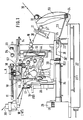
- a winding finger 10 rotatable about an axis A with solid lines in its starting position and with dashed lines in a pivot position rotated by 90 °, a rack 11 serving to drive it, and a loop pivot lever 12 of the actual knotting device , a clamping hook 14 coupled to the loop pivot lever 12 via a spiral usable cylinder 13, a central drive cylinder 15 for the last-mentioned parts and a thread drive device 16.
- a thread guide 17 and a thread brake upstream of it in the form of an electromagnetically actuated ball brake 18 and one of the thread clamps 19 associated with each thread guide and combined with thread scissors and their drive mechanism 20 for opening and closing From the knotting device upstream parts of the thread changing device, one of, for example, four thread guides 17 and a thread brake upstream of it in the form of an electromagnetically actuated ball brake 18 and one of the thread clamps 19 associated with each thread guide and combined with thread scissors and their drive mechanism 20 for opening and closing can be seen.
- FIG. 1 shows a housing 27 for electronic control parts, which are arranged on a circuit board 27.1, and a compressed air regulating valve 28 of the control part of the thread changing device.
- FIG. 1 shows the thread changing device in a normal operating position, i.e. at time t0 in the time diagram according to FIG 4.
- a thread reserve thread compensation path
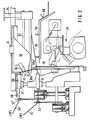
- FIG. 2 shows, on an enlarged scale compared to FIG. 1, the area of the winding finger 10 of the thread changing device after it has been prepared for a thread changing, that is to say in the time diagram according to FIG. 4 between the times t2 and t3.
- the old thread 30 continues to run over a thread guide eyelet 32 to its thread in the normal position leader 17 and in the manner described above through the thread changing device.
- Another of the total of four thread guides 17 ' is moved together with the upstream thread guide eyelet 32' from the normal position upwards.
- the thread guided by him is called new thread below, is designated by the reference number 30 'and is held with its end 30a' in the associated, in a manner not shown combined with scissors thread clamp 19 '.
- the new thread 30' can be gripped by an urging bracket 33 which is fastened on a pivot shaft 34. 3, the end section 30b 'of the new thread 30' and pushes it into the gripping area of the winding finger 10.
- the pivoting movement of the pressing bracket 33 about the pivot axis 34 is derived in a manner not shown from the drive of the winding finger 10 and for example effected by means of two switching pins 61 and 62.
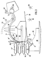
- FIG. 3 shows, as an additional thread securing device, a thread guide edge 35 which runs along the movement path of the winding finger 10 and which is formed on a stationary guide plate 36 which also carries an elastic end stop 37 for the urging bracket 33.
- Fig. 2 the overall designated by the reference numeral 20 drive mechanism for opening and closing each combined with a pair of thread scissors, selectable thread clamps 19, 19 'is shown, which will not be described here in detail.
- This mechanism is driven at the beginning of the working stroke of the drive cylinder ders 15, which moves with its piston rod 15.1 one shown in FIG. 1, on a guide rod 38 longitudinally movable drive carriage 39.
- Fig. 5 shows the loop pivot lever 12 shown in Fig. 1 in its starting position in its operating position, in which it dips with its free end 12.1 into the slot 10.1 of the winding finger 10 designated in Fig. 3, after on the winding finger 10 from the new thread 30 'a closed loop 40 has been formed.
- the knotting device assumes this position at time t5 of the time diagram in FIG. 4.
- the loop pivot lever 12 has the shape of a curved lance, which is attached to an arm 42a of a two-armed pivot lever 42, the other of which, not shown in FIG. 5 Arm is coupled to the drive carriage 39 of the main drive cylinder 15.
- a drive lever 43 Parallel to that Arm 42a and connected to it is a drive lever 43 which engages with its tip 43.1 in the spiral groove 44 of the tubular spiral cylinder 13 rotatable about its longitudinal axis (see also FIG. 1) and upon the pivoting movement of the loop pivot lever 12 a rotary movement of the spiral cylinder 13 causes.
- the clamping hook 14 is fastened, which can be seen in detail in FIG. 6.
- the lance-shaped loop pivot lever 12 is provided on its inside with an edge recess 45.
- the thread loop 50 formed from the running old thread 30 runs between the upper thread guide groove 12.3 formed in the loop swivel lever 12 and a thread guide notch 10.4 (FIG. 8) formed in a lower nose 10.2 of the winding finger at a distance from the lower edge of the loop swivel lever 12.
- FIG. 6 shows the clamping hook 14, which can be pivoted about the axis of rotation 46 of the spiral utility cylinder 13 and is drivingly coupled to the loop pivot lever 12 and is designed as a pivot lever. It is adjustably mounted in a plane running perpendicular to the swivel plane of the loop swivel lever 12 and is provided at its free end with a piercing tip 14.1 and a hook 14.2. With these parts, which are only indicated schematically in FIG. 5, it projects in the position of the loop pivoting lever 12 shown in FIG. 5 through the transverse slot 10.3 of the winding finger 10 shown in FIGS. 2.5 and 8 and through the recess 45 of the free one End 12.1 of the loop pivot lever 12 and thus also through the thread loop 50 formed from the running old thread.
- the hook 14.2 is a move Licher jaws 47 (Fig. 6, 11) assigned, which is connected to a shift rod 48 which is connected to the end of one arm of a two-armed pivot lever 49.
- the pivot lever 49 is mounted on the pivotable clamping hook 14 so as to be pivotable about an axis 51 and carries on its other lever arm a control pin 52 which engages in a control groove 53 of a stationary control part 54.
- 5 and 6 show the knotting device between the times t5 and t6 of the time diagram of FIG. 4 in a position in which the knot formation is prepared and from which the knot formation is triggered by a switching pulse supplied by the control part at the time t6.
- the position of the individual knot organs is monitored by electro-optically or electromagnetically active sensors S1-S5 (FIGS. 1, 6). If one of these sensors does not respond, this means that the preparation position is faulty, and the triggering pulse for knot formation is not given by the control part.
- a switch S1 is actuated by the rack 11 when the winding finger 10 is in its end position for pivoting the loop pivot lever 12 and the clamping hook 14.
- a sensor S2 monitoring the loop pivot lever 12 detects its pivoting in.
- a sensor S3 reports that the swivel lever 42 moves back when the knot is formed in order to trigger the compensator thread brake 21.
- a sensor S4 influences the ball brakes 18, 18 '.
- the thread changing device with its parts is in the position shown in FIG. 1.
- the new thread guide 17 ' are still in its normal position, which is designated in Fig. 4 with "off”.
- the thread clamp 19 'for the new thread 30' is closed and holds the thread end 30a '.
- the ball brake 18 'for the new thread 30' is open.
- the winding finger 10 is in its starting position, which is labeled "off” in FIG. 4, as is the push bracket 33, the loop pivot lever 12 and the hook scissors 14.
- the compensator thread brake 21 is open, the thread guide 17 of the old thread is located in its normal position, which is labeled "off”, and the ball brake 18 for the old thread 30 is open, so that the thread 30 brakes the thread changing device braked on the path shown in FIG. 1.
- the preparation of the thread changing device for knot formation begins by moving the thread guide 17 'for the new thread 30' from the normal position upward (see FIG. 2).
- the winding finger 10 is set in rotation, which is indicated in the time diagram of FIG. 4 by the position "on".
- the urging bracket 33 is pivoted in the direction of the winding finger 10 and presents the new thread 30 'with its end portion 30b' to the winding finger 10.
- Fig 3 and 7 show the position of the winding finger 10 which can be rotated about the axis A and of the thrust bracket 33 which cooperates with it at the time t2.
- the push bracket 33 returns to its starting position. Up to this point, the winding finger 10 has made about 1 1/2 turns and has already almost completed the loop 40 from the new thread 30 '. Shortly thereafter, at time t4, the ball brake 18 ', through which the new thread 30' passes, is partially activated, so that a braking force is exerted on the new thread 30 '. This braking position is designated "1/2" in the time diagram of FIG. 4.
- the winding finger 10 remains in the position shown in FIG. 8. It can be seen from the time diagram in FIG. 4 that it is only turned back to its starting position shown in FIGS. 1 and 3 at time t12, that is to say after the knotting process has ended.
- the position of the loop 40 on the winding finger can be seen from FIG. Fig. 8 also shows the formed in the lower winding finger tip 10.2 thread guide notch 10.4 and the transverse slot 10.3 of the winding finger 10. In this position, the new thread 30 'is still fixed, while the old thread 30 continues over the centering part 29 to the thread processing point.
- the reached position of the winding finger 10 is determined by the sensor S1 of the control part of the thread changing device, which then causes the knotting process to continue.
- the loop pivot lever 12 is first pivoted into the operating position shown in FIGS. 5 and 6, and immediately thereafter the clamping hook 14 with its hook 14.2 is pivoted into the slot 10.1 or 10.3 of the winding finger 10.
- the loop pivot lever 12 grasps the old thread 30 shortly before the centering part 29 with its free end 12.1 and places it when the free end 12.1 is immersed in the thread guide notch 10.4 in FIG. 8 in the lower tip 10.2 of the winding finger.
- Fig. 9 shows this time of immersion of the free end 12.1 of the loop pivot lever 12. From Fig.
- a loop wiping part 55 is shown, which engages with a nose in a longitudinal groove 12.2 of the loop pivot lever 12 and this ensures that when later pivoting back of the loop pivot lever 12, the loop 40 pulled by the winding finger 10 does not get caught on the loop pivot arm 12.
- the compensator swivel arm 23 is locked by immersing the coupling bolt 25 in the guide slot 26 'of the control plate 26 in its position determining the maximum length of the compensation path.
- the thread reserve held here can be released between times t8 and t10.
- FIG. 10 also shows the clamping hook 14 pivoted into the winding finger 10, the hook 14.2 in the region of the recess 45 of the loop pivot lever 12 designated in FIG. 5 by the loop 50 running over the free end 12.1 of the loop pivot lever 12 (FIG. 5) of the old thread 30 has passed and the end portion 30b 'of the end 30a' still in the clamp 19 'held at rest second thread 30' has grasped.
- the first thread 30 continues to run to the thread processing point.
- the knotting device is ready for the knotting process.
- the sensors S1, S2 of the control part of the thread changing device are used to check whether the device parts have all assumed the position specified in them and shown in FIG. 10.
- the subsequent knotting process then becomes a calculated one correct time t6 triggered by a control signal given to the drive devices of the knotting device.
- the clamping hook 14 is brought into a "clamping" position, which occurs according to FIG. 6 when the clamping hook 14 is pivoted counterclockwise in the control curve region 53.2, and the loop pivot lever 12 is pivoted back out of the winding finger 10 again .
- the end portion 30b 'of the second thread 30' is clamped between the hook 14.2 and the clamping jaw 47 of the clamping hook 14.
- the ball brake 18 'for the new thread 30' is switched to its full braking position, so that no new thread 30 'can be retightened by the thread guide 17'.
- the clamping hook 14 pulls the end portion 30b 'of the new thread 30' through the loop 50 of the old thread 30 and through the loop 40 of the new thread 30 '.
- the thread clamp 19 ' is opened at the time t7, so that it releases the end 30a' of the new thread 30 'which was previously clamped there.
- the restoring movement of the loop pivot lever 12 and the clamping hook 14 is controlled by means of the main drive cylinder 15 shown in FIG. 1.
- the drive cylinder 15 When the drive cylinder 15 is reversed, compressed air which is released is passed into the blowing nozzle 16 acting as a thread drive device, through which the old thread 30 is passed.
- the old thread 30 is driven in the thread running direction, thereby achieving a rapid and controlled regression of the thread loop 50 which dissolves again when the loop pivot lever 12 is withdrawn from the winding finger 10.
- the old thread 30 at the now knot formation held taut. There is no dependence on whether the old thread 30 is running at full speed at this time or only at a low speed when the knitting machine is running slowly, or whether the old thread 30 may be stopped at this moment.
- the blow nozzle 16 only works for a short time and transmits a drive pulse that flattens out at the time t8 and t9.
- the compensator thread brake 21 is then actuated for a short time, up to time t10, in accordance with the time diagram in FIG. 4, and the run of the old thread 30 is thus briefly interrupted.
- the main drive cylinder 15 has released the coupling bolt 25 in the control plate 26 at this time, so that old thread 30 can still be delivered to the thread processing point from the fixed compensation path formed on the compensator swivel arm 23 with the deflection roller 24.
- the loop pivot lever 12 continues to decrease, the loop stripping part 55 shown in FIG. 9 taking effect.
- the hook scissors 14 pulls through the loop 50 and the loop 40 drawn end portion 30b 'of the new thread 30' during its pivoting back movement in the effective range of the control curve 53 shown in FIG. 6.
- the clamping hook 14 has reached its end position and cut the loop 56 open.
- the ball brake 18 'for the new thread 30' is now fully opened again, so that the new thread 30 'knotted on the old thread 30' can pass freely.
- the compensator thread brake 21 is opened again.
- the knot 60 and behind it the new thread 30 'can continue to the thread processing point, where the knot appears exactly at a desired knitted point.
- the thread guide 17 ' is moved back into its starting position, that is to say into the position which the thread guide 17 has already assumed for the old thread 30 in FIGS. 9 to 11.
- the running new thread 30 ' is moved completely out of the swivel range of the winding finger 10, so that the winding finger can then be moved back to its initial position shown in FIGS. 1 and 3 at the time t12 from its position shown in FIGS. 9 to 11 .
- the knotting device is again in a starting position, from which a new knotting process can be initiated.
Landscapes
- Engineering & Computer Science (AREA)
- Textile Engineering (AREA)
- Knitting Machines (AREA)
Abstract
Description
Die Erfindung betrifft eine Fadenwechseleinrichtung, insbesondere für Strickmaschinen, mit einer Knotvorrichtung zum Anknoten eines neuen Fadens an einen alten Faden bei einem Fadenwechsel, mit Fadenklemmen und Schneidorganen für den neuen und den alten Faden, die Knotvorrichtung bestehend aus einem den neuen Faden erfassenden und in eine geschlossene Schleife legenden Wickelfinger, einem den alten Faden während des Fadenablaufes als offene Schlaufe in die Schleife einführenden Schlaufenschwenkheben, und einem durch die Schlaufe hindurchgreifenden und das Ende des neuen Fadens erfassenden beweglichen Klemmhaken.The invention relates to a thread changing device, in particular for knitting machines, with a knotting device for knotting a new thread on an old thread during a thread change, with thread clamps and cutting elements for the new and the old thread, the knotting device consisting of a grasping the new thread and into one closed loop-laying wrap finger, a loop pivoting arm that introduces the old thread as an open loop into the loop while the thread is running, and a movable clamping hook that reaches through the loop and detects the end of the new thread.
Eine Fadenwechseleinrichtung mit den vorstehend genannten Merkmalen ist bereits in der DE-OS 32 44 887 vorgeschlagen worden. Die vorliegende Erfindung betrifft eine Weiterbildung einer solchen Fadenwechseleinrichtung. Ihr liegt die Aufgabe zugrunde, eine Fadenwechseleinrichtung der genannten Art so auszubilden, daß ihre Betriebssicherheit im Hinblick auf die Knotenbildung und eine taktgerechte Weiterleitung des Fadens zu der Fadenverarbeitungsstelle erhöht wird.A thread changing device with the features mentioned above has already been proposed in DE-OS 32 44 887. The present invention relates to a further development of such a thread changing device. You lie the task is to design a thread changing device of the type mentioned in such a way that its operational reliability with regard to knot formation and a timely forwarding of the thread to the thread processing point is increased.
Die gestellte Aufgabe wird mit der genannten Fadenwechseleinrichtung erfindungsgemäß dadurch gelöst, daß in Fadenabzugsrichtung hinter der Knotvorrichtung eine über einen federbelasteten Schwenkarm führende Fadenkompensationsstrecke festgelegter Maximallänge und eine vorgesetzte, kurzfristig in Abhängigkeit von der Stellung des beweglichen Klemmhakens und/oder des Schlaufenschwenkhebels betätigbare Kompensator-Fadenbremse vorgesehen sind und daß der Klemmhaken mit einer Schere zum Schneiden des neuen Fadens kombiniert ist.The stated object is achieved with the thread changing device according to the invention in that in the thread take-off direction behind the knotting device there is a maximum length of thread compensation path leading via a spring-loaded swivel arm and a superior compensator thread brake which can be actuated briefly as a function of the position of the movable clamping hook and / or the loop pivot lever are and that the clamping hook is combined with scissors for cutting the new thread.
Auch bei der neuen Fadenwechseleinrichtung erfolgt die Bildung des Knotens am laufenden alten Faden, was zu den bereits in der DE-OS 32 44 887 aufgeführten wesentlichen Vorteilen gegenüber Knotvorrichtungen führt, bei welchen eine Knotenbildung nur an stehenden Fäden ausgeführt werden kann. Der laufende alte Faden wird lediglich kurzfristig zum Festziehen des gebildeten Fadenknotens angehalten. Dadurch wird ein einwandfrei fester Fadenknoten erzielt, der sich bei seiner Weiterbewegung zu einer Fadenverarbeitungsstelle auch bei wechselnden Zugbeanspruchungen nicht mehr lösen kann. Die Fadenzufuhr an der Fadenverarbeitungsstelle wird aber trotzdem nicht unterbrochen, weil während der kurzfristigen Betätigung der Kompensator-Fadenbremse Faden aus der Fadenkompensationsstrecke geliefert wird. Die Fadenvorratsstrecke wird durch Arretieren eines Kompensator-Schwenkarmes auf eine genau festgelegte Maximallänge gesetzt. Durch die festgelegte Maximallänge der Fadenkompensationsstrecke ist die Strecke, die der Fadenknoten von der Knotvorrichtung bis zur Fadenverarbeitungsstelle durchläuft, genau vorgegeben und kann als fester Wert in einem Steuerteil der Fadenwechseleinrichtung verwertet werden, der auch die Knotvorrichtung der Fadenwechseleinrichtung im Hinblick auf eine genaue Plazierung eines gebildeten Knotens im Gestrick steuert. Durch die Kombination des Klemmhakens, mit welchem bei der Knotenbildung das Ende des neuen Fadens erfaßt und durch die aus dem alten Faden gebildete Schlaufe hindurchgezogen wird, mit einer Schere, wird erreicht, daß eine sich hierbei möglicherweise bildende, im Knoten verankerte Endschleife des neuen Fadens aufgeschnitten wird oder überhaupt das Ende des neuen Fadens beschnitten wird und ein gesonderter Vorgang des Beschneidens der Fadenenden an einer gesonderten Schneidstation entfallen kann.With the new thread changing device, too, the knot is formed on the running old thread, which leads to the essential advantages already mentioned in DE-OS 32 44 887 compared to knotting devices in which knot formation can only be carried out on standing threads. The running old thread is only stopped briefly to tighten the thread knot formed. In this way, a perfectly firm thread knot is achieved which, when it moves on to a thread processing point, can no longer be loosened even in the event of changing tensile stresses. The thread feed at the thread processing point is nevertheless not interrupted because thread is supplied from the thread compensation path during the short-term actuation of the compensator thread brake. The thread supply line is by locking a compensator swivel arm on one precisely defined maximum length. Due to the specified maximum length of the thread compensation path, the path through which the thread knot runs from the knotting device to the thread processing point is precisely predetermined and can be used as a fixed value in a control part of the thread changing device, which also the knotting device of the thread changing device with regard to an exact placement of a formed one Knots in the knitted fabric controls. The combination of the clamping hook, with which the end of the new thread is grasped during knot formation and pulled through the loop formed from the old thread, with a pair of scissors, means that an end loop of the new thread, which may be formed and is anchored in the knot, is achieved is cut open or the end of the new thread is cut at all and a separate process of trimming the thread ends at a separate cutting station can be omitted.
Die Fadenwechseleinrichtung kann erfindungsgemäß zusätzlich in Fadenabzugsrichtung zwischen der Knotvorrichtung und der Kompensator-Fadenbremse eine kurzfristig betätigbare Fadenantriebsvorrichtung aufweisen, die beispielsweise aus einer vom Faden durchlaufenen Blasdüse besteht. Mit dieser Fadenantriebsvorrichtung wird der Vorteil erzielt, daß eine einwandfreie Knotenbildung auch bei langsam laufender Maschine und selbst bei stehender Maschine, bei welcher auf den alten Faden kein Zug von der Maschenverarbeitungsstelle her ausgeübt wird, gewährleistet ist. Die Fadenantriebsvorrichtung erbringt die für ein Festziehen des gebildeten Knotens vorgesehene Bewegung des alten Fadens, wenn anderseits der Klemmhaken einen Zug auf den neuen Faden ausübt.According to the invention, the thread changing device can additionally have a thread drive device that can be actuated for a short time in the thread pull-off direction between the knotting device and the compensator thread brake, which consists, for example, of a blowing nozzle through which the thread runs. With this thread drive device, the advantage is achieved that a perfect knot formation is guaranteed even when the machine is running slowly and even when the machine is stopped, in which no tension is exerted on the old thread from the stitch processing point. The thread drive device provides the movement of the old thread intended for tightening the knot formed when, on the other hand, the clamping hook exerts a pull on the new thread.
Die angestrebte erhöhte Betriebssicherheit der Fadenwechseleinrichtung, insbesondere ihrer Knotvorrichtung, läßt sich durch weitere Zusatzmerkmale noch erhöhen. So können die auswählbaren Fäden dem Wickelfinger der Knotvorrichtung zweckmäßig jeweils über eine Fadenbremse zugeleitet werden, deren Bremskraft in Abhängigkeit von der Stellung mindestens eines der Organe der Knotvorrichtung veränderlich ist. Hierbei haben sich elektromagnetisch beeinflußbare Fadenbremsen bewährt, mit denen während Abschnitten des Knotvorganges entweder eine bestimmte, die auf dem Wickelfinger mit dem neuen Faden gebildete Fadenschleife straffhaltende Bremskraft ausgeübt oder auch ein kurzfristiges völliges Blockieren während des Festziehens eines gebildeten Knotens erreicht wird.The desired increased operational reliability of the thread changing device, in particular its knotting device, can be further increased by additional features. Thus, the selectable threads can be expediently fed to the winding finger of the knotting device in each case via a thread brake, the braking force of which can be varied depending on the position of at least one of the organs of the knotting device. Here, thread brakes that can be influenced electromagnetically have proven themselves, with which during sections of the knotting process either a certain braking force which tightens the braking force formed on the winding finger with the new thread is exerted, or a brief complete blocking is achieved during the tightening of a knot formed.
Die Knotvorrichtung kann vorteilhafterweise zusätzlich mit mechanisch wirksamen Fadensicherungsorganen versehen sein, die einen in Richtung auf den Wickelfinger bewegbaren, auf den neuen Faden einwirkenden Drängbügel und eine entlang eines Abschnittes der Bewegungsstrecke des Wickelfingers verlaufende stationäre Fadenleitkante umfassen können. Mit diesen Organen wird in der kritischen Phase der Schleifenbildung der neue Faden in den Bereich des Wickelfingers gebracht, so daß er mit seinem Endbereich vom Wickelfinger sicher erfaßt und während des Wickelvorganges auch im Einflußbereich des Wickelfingers sicher gehalten wird. Ein weiterer kritischer Punkt ist in jeder Knotvorrichtung die Gefahr des Sitzenbleibens der gebildeten Fadenschleife auf dem Schlaufenschwenkhebel am Beginn des eigentlichen Knotvorganges. Zur Beseitigung dieser Gefahr kann erfindungsgemäß als Fadensicherungsorgan ein Fadenabstreifteil zum Erfassen und Abstreifen der Fadenschleife vom Wickelfinger beim Rückschwenken des Schlaufenschwenkarmes vorgesehen sein. Zur Erhöhung der Betriebssicherheit können mit dem Steuerteil der Fadenwechseleinrichtung verbundene Sensoren vorgesehen sein, mit welchen mindestens die Stellung des Schlaufenschwenkhebels und/oder des Klemmhakens und/oder der Fadenbremsen, vorteilhafterweise aber auch die Stellung des Wickelfingers oder der diesen Teilen der Knotvorrichtung zugeordneten Antriebsvorrichtung erfaßbar ist.The knotting device can advantageously additionally be provided with mechanically effective thread securing members, which can comprise a push bracket which can be moved in the direction of the winding finger and act on the new thread, and a stationary thread guide edge running along a section of the movement path of the winding finger. With these organs, the new thread is brought into the area of the winding finger in the critical phase of the loop formation, so that it is securely gripped by the winding finger with its end area and is also held securely in the area of influence of the winding finger during the winding process. Another critical point in every knotting device is the risk of the thread loop formed remaining on the loop pivoting lever at the beginning of the actual knotting process. To eliminate this danger, a thread wiping part can be provided according to the invention as a thread securing element for grasping and wiping off the thread loop from the winding finger when the loop pivot arm is pivoted back be. To increase operational reliability, sensors connected to the control part of the thread changing device can be provided, with which at least the position of the loop pivot lever and / or the clamping hook and / or the thread brakes, but advantageously also the position of the winding finger or the drive device assigned to these parts of the knotting device can be detected .
Zur Erhöhung der Betriebssicherheit der Fadenwechseleinrichtung gemäß der Erfindung kann auch eine stationäre Steuerkurve vorgesehen sein, an welcher der Klemmhaken entlangführbar ist und die auf seine Klemme und die mit ihm kombinierte Schere einwirken kann. Auch kann hierzu der Schlaufenschwenkhebel in seiner Betriebsstellung mit seinem eine Fadenlaufnut für den alten Faden aufweisenden freien Ende gegen einen Anschlag anliegen, der seine Fadenlaufnut zu einem geschlossenen Fadendurchlaufkanal abdeckt, so daß der alte Faden, der zur Fadenverarbeitungsstelle weiterläuft, vor der Knotenbildung nicht herausspringen kann, und der außerdem die aus dem neuen Faden gebildete Schleife an einem Abgleiten vom Wickelfinger hindert.To increase the operational reliability of the thread changing device according to the invention, a stationary control cam can also be provided, along which the clamping hook can be guided and which can act on its clamp and the scissors combined with it. For this purpose, the loop swivel lever in its operating position with its free end having a thread running groove for the old thread can rest against a stop which covers its thread running groove to form a closed thread passage channel, so that the old thread which continues to the thread processing point cannot jump out before the knot is formed , and which also prevents the loop formed from the new thread from sliding off the winding finger.
Bei einer erfindungsgemäß ausgebildeten Fadenwechseleinrichtung kann das Verfahren zur Knotenbildung durch Erfassen eines ausgewählten neuen Fadens durch den Wickelfinger, Bilden einer geschlossenen Schleife des neuen Fadens auf dem Wickelfinger, Einführen einer offenen Schlaufe des alten Fadens in die Schleife des neuen Fadens mittels des Schlaufenschwenkhebels und Hindurchführen des Klemmhakens durch die offene Schlaufe des alten Fadens, Erfassen des Endes des neuen Fadens durch den Klemmhaken und anschließendes Durchziehen des Fadenendes durch die Schlaufe des alten Fadens und Rückbewegung des Schlaufenschwenkhebels gsgemäß durch folgende zusätzliche Verfahrensschritte gekennzeichnet sein:
- a) Einwärtsbewegung des Drängbügels zum Wickelfinger bei der Bildung der Fadenschleife;
- b) Aktivieren der Fadenbremse für den neuen Faden vor Beendigung der Bildung der Fadenschleife;
- c) Festlegen der Fadenkompensationsstrecke in ihrer Maximallänge vor Beginn der eigentlichen Knotenbildung;
- d) bei der Rückwärtsbewegung von Schlaufenschwenkhebel und Klemmhaken bei der eigentlichen Knotenbildung mindestens über einen Teil der Bewegungsstrecke Schalten der Fadenbremse für den neuen Faden aus Vollbremsung und gleichzeitig kurzzeitiges Aktivieren der zwischen der Knotvorrichtung und der Kompensator-Fadenbremse angeordneten Fadenantriebsvorrichtung in Fadenlaufrichtung;
- e) in einem Endbereich der Rückwärtsbewegungsstrecke des Klemmhakens zunächst kurzzeitiges Schließen der Kompensator-Fadenbremse und anschließend Schneiden des neuen Fadens mittels der mit dem Klemmhaken kombinierten Schere;
- f) nach Schließen der Kompensator-Fadenbremse Freigabe des Kompensator-Schwenkarmes der Fadenkompensationsstrecke.
- a) Inward movement of the push bracket to the winding finger during the formation of the thread loop;
- b) activating the thread brake for the new thread before the formation of the thread loop has ended;
- c) Definition of the thread compensation path in its maximum length before the actual knot formation begins;
- d) when the loop pivot lever and clamping hook move backwards during the actual knot formation, at least over part of the movement distance, switching the thread brake for the new thread from full braking and at the same time briefly activating the thread drive device arranged between the knotting device and the compensator thread brake in the thread running direction;
- e) in an end region of the backward movement path of the clamping hook, first briefly closing the compensator thread brake and then cutting the new thread by means of the scissors combined with the clamping hook;
- f) after the compensator thread brake is released, the compensator swivel arm of the thread compensation path is released.
Nachfolgend wird ein Ausführungsbeispiel der erfindungsgemäß ausgebildeten Fadenwechseleinrichtung anhand der beiliegenden Zeichnung näher erläutert.An exemplary embodiment of the thread changing device designed according to the invention is explained in more detail below with reference to the accompanying drawing.
Im einzelnen zeigen:
- Fig. 1 eine Seitenansicht der Fadenwechseleinrichtung;
- Fig. 2 eine gegenüber Fig. 1 vergrößerte Teilseitenansicht der Fadenwechseleinrichtung;
- Fig. 3 eine Draufsicht auf einen Teil der aus Fig. 2 ersichtlichen Teile der Fadenwechseleinrichtung;
- Fig. 4 ein Zeitdiagramm der Funktionsweise einzelner Teile der Fadenwechseleinrichtung;
- Fig. 5 eine gegenüber Fig. 1 vergrößerte Teilseitenansicht der Fadenwechseleinrichtung mit dem Schlaufenschwenkhebel;
- Fig. 6 eine Draufsicht auf den Wickelfinger und den Klemmhaken der Knotvorrichtung;
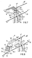
- Fig. 7 - 11 perspektivische Darstellungen des Wickelfingers und der mit ihm zusammenwirkenden Teile der Knotvorrichtung in verschiedenen Stadien der Knotenbildung.
- Fig. 1 is a side view of the thread changing device;
- FIG. 2 shows a partial side view of the thread changing device, enlarged compared to FIG. 1;
- FIG. 3 shows a plan view of a part of the parts of the thread changing device which can be seen from FIG. 2;
- 4 shows a time diagram of the functioning of individual parts of the thread changing device;
- FIG. 5 is a partial side view of the thread changing device with the loop swivel lever, enlarged in relation to FIG. 1;
- 6 shows a plan view of the winding finger and the clamping hook of the knotting device;
- FIGS. 7-11 are perspective representations of the winding finger and the parts of the knotting device interacting with it in various stages of knot formation.
In der Gesamtseitenansicht der Fig. 1 sind bei abgenommener Schutzhaube alle Teile der Fadenwechseleinrichtung angedeutet, jedoch nur die erfindungswesentlichen Teile näher gekennzeichnet und in den Teildarstellungen der Fig. 2, 3, 5 und 6 auch näher gezeigt. Auf eine genaue Beschreibung des Antriebs des Wickelfingers 10, des mit ihm zusammenwirkenden Schlaufenschwenkhebels 12 und des Klemmhakens 14 der Knotvorrichtung sowie der Antriebstelle zur Auswahl einzelner Fadenführer 17 der Fadenwechseleinrichtung und der jedem Fadenführer zugeordneten Fadenklemme und Fadenschneidvorrichtung 19 wird bewußt verzichtet, weil diese Antriebs- und Vorrichtungsteile nicht unmittelbarer Gegenstand der Erfindung sind und teils in der DE-OS 32 44 887 beschrieben oder von nicht knotenden Fadenringelapparaten her grundsätzlich vorbekannt sind.
Aus der Gesamtdarstellung der Fig. 1 sind von der eigentlichen Knotvorrichtung ein um eine Achse A drehbarer Wickelfinger 10 mit ausgezogenen Linien in seiner Ausgangsstellung und mit gestrichelten Linien in einer um 90° dazu gedrehten Schwenkstellung, eine zu seinem Antrieb dienende Zahnstange 11, ein Schlaufenschwenkhebel 12, ein mit dem Schlaufenschwenkhebel 12 über einen Spiralnutzylinder 13 antriebsmäßig gekoppelter Klemmhaken 14, ein zentraler Antriebszylinder 15 für die zuletzt genannten Teile und eine Fadenantriebsvorrichtung 16 ersichtlich. Von der Knotvorrichtung vorgeschalteten Teilen der Fadenwechseleinrichtung ist einer von beispielsweise vier Fadenführern 17 und eine ihm vorgeschaltete Fadenbremse in Form einer elektromagnetisch betätigbaren Kugelbremse 18 und eine der jedem Fadenführer zugeordneten und mit einer Fadenschere kombinierten Fadenklemmen 19 mit ihrem Antriebsmechanismus 20 zum Öffnen und Schließen ersichtlich. Von den der eigentlichen Knotvorrichtung nachgeschalteten Teilen sind außer der Fadenantriebsvorrichtung 16 eine Kompensator-Fadenbremse 21 und ein um eine Schwenkachse 22 verschwenkbarer Kompensator-Schwenkhebel 23 mit einer Fadenumlenkrolle 24 an seinem freien Ende gezeigt. Der Schwenkhebel 23 ist über einen Koppelungsbolzen 25 mit einer durch den Hauptzylinder 15 bewegbaren, einen Führungsschlitz 26′ aufweisenden Steuerplatte 26 zwangskoppelbar. Von dem Steuerteil der Fadenwechseleinrichtung zeigt Fig. 1 ein Gehäuse 27 für elektronische Steuerungsteile, die auf einer Leiterplatte 27.1 angeordnet werden, und ein Druckluft-Regulierventil 28. Fig. 1 zeigt die Fadenwechseleinrichtung in einer normalen Betriebsstellung, also zum Zeitpunkt t0 im Zeitdiagramm nach Fig. 4. In dieser Stellung durchläuft ein nachfolgend als alter Faden bezeichneter Faden 30, von einem nicht dargestellten Fadenspeicher kommend, nacheinander die ihm zugeordnete und freigegebene Kugelbremse 18, seinen in normaler Ausgangslage befindlichen Fadenführer 17, ein stationäres, allen Fäden gemeinsames Zentrierteil 29 der Knotvorrichtung, die inaktive, als Blasdüse ausgebildete Fadenantriebsvorrichtung 16 und die ebenfalls inaktive Kompensator-Fadenbremse 21, und läuft uber eine erste fest angeordnete Fadenrolle 31′, über die Fadenrolle 24 des in seiner maximalen Schwenkbewegung befindlichen Kompensator-Schwenkarmes 23 und über eine zweite fest angeordnete Fadenrolle 31 zu einer Fadenverarbeitungsstelle einer Textilmaschine, insbesondere Strickmaschine. Zwischen den Fadenrollen 31, 31′ wird eine Fadenreserve (Fadenkompensationsstrecke) gebildet, deren Länge durch die jeweilige Lage des durch eine Führungsbahn 59 stabilisierten Kompensator-Schwenkarmes 23 bestimmt ist.In the overall side view of FIG. 1, with the protective hood removed, all parts of the thread changing device are indicated, but only the parts essential to the invention are identified in more detail and also shown in greater detail in the partial representations of FIGS. 2, 3, 5 and 6. On a precise description of the drive of the
From the overall illustration in FIG. 1, a winding
Fig. 2 zeigt in gegenüber Fig. 1 vergrößertem Maßstab den Bereich des Wickelfingers 10 der Fadenwechseleinrichtung nach deren Vorbereitung für einen Fadenwechsel, also im Zeitdiagramm nach Fig. 4 zwischen den Zeitpunkten t2 und t3. Der alte Faden 30 läuft weiterhin über eine Fadenleitöse 32 zu seinem in der Normalstellung befindlichen Faden führer 17 und in der vorstehend beschriebenen Weise weiter durch die Fadenwechseleinrichtung. Ein anderer der insgesamt vier Fadenführer 17′ ist zusammen mit der vorgeschalteten Fadenleitöse 32′ aus der Normalstellung nach oben verschoben. Der von ihm geführte Faden wird nachfolgend neuer Faden genannt, ist mit der Bezugsziffer 30′ bezeichnet und wird mit seinem Ende 30a′ in der ihm zugeordneten, in nicht näher dargestellten Weise mit einer Schere kombinierten Fadenklemme 19′ gehalten. Durch das Anheben des Fadenführers 17′ ergibt sich ein nach oben gerichteter Fadenendbereich 30b′ zwischen dem festgeklemmten Fadenende 30a′ und dem Fadenführer 17′. In diesem Endbereich 30b′ kann der neue Faden 30′ von einem Drängbügel 33 erfaßt werden, der auf einer Schwenkwelle 34 befestigt ist. Der Drängbügel 33 erfaßt gemäß Fig. 3 den Endabschnitt 30b′ des neuen Fadens 30′ und schiebt ihn bis in den Greifbereich des Wickelfingers 10. Die Schwenkbewegung des Drängbügels 33 um die Schwenkachse 34 wird in nicht dargestellter Weise vom Antrieb des Wickelfingers 10 abgeleitet und beispielsweise mittels zweier Schaltbolzen 61 und 62 bewirkt.FIG. 2 shows, on an enlarged scale compared to FIG. 1, the area of the winding
Fig. 3 zeigt als zusätzliche Fadensicherungseinrichtung eine entlang der Bewegungsstrecke des Wickelfingers 10 verlaufende Fadenleitkante 35, die an einem stationären Führungsblech 36 ausgebildet ist, das auch einen elastischen Endanschlag 37 für den Drängbügel 33 trägt. In Fig. 2 ist auch der insgesamt mit der Bezugsziffer 20 bezeichnete Antriebsmechanismus zum Öffnen und Schließen der jeweils mit einer Fadenschere kombinierten, vorwählbaren Fadenklemmen 19, 19′ dargestellt, der hier aber nicht im einzelnen beschrieben werden soll. Angetrieben wird dieser Mechanismus zu Beginn des Arbeitshubes des Antriebszylin ders 15, der mit seiner Kolbenstange 15.1 einen aus Fig. 1 ersichtlichen, auf einer Führungsstange 38 längsbewegbaren Antriebsschlitten 39 bewegt.3 shows, as an additional thread securing device, a
Fig. 5 zeigt den in Fig. 1 in seiner Ausgangsstellung dargestellten Schlaufenschwenkhebel 12 in seiner Betriebsstellung, in welcher er mit seinem freien Ende 12.1 in den in Fig. 3 bezeichneten Schlitz 10.1 des Wickelfingers 10 eintaucht, nachdem auf dem Wickelfinger 10 aus dem neuen Faden 30′ eine geschlossene Fadenschleife 40 gebildet worden ist. Diese Stellung nimmt die Knotvorrichtung im Zeitpunkt t5 des Zeitdiagramms der Fig. 4 ein. Bei der Schwenkbewegung des Schlaufenschwenkhebels 12 um eine Schwenkachse 41 im Gegenuhrzeigersinne aus der Ruhestellung nach Fig. 1 in die Betriebsstellung nach Fig. 5 nimmt sein freies Ende 12.1, das mit einer Fadenführungsnut (12.3) versehen ist, nahe des Zentrierteiles 29 den laufenden alten Faden 30 auf und bewegt ihn bei ununterbrochenem Fadenlauf zu einer offenen Schlaufe 50 durch die geschlossene Schleife 40 des neuen Fadens 30′ hindurch in den Wickelfinger 10 bis in eine Stellung hinein, in welcher das freie Ende 12.1 gegen einen Anschlag 57 zur Anlage kommt, so daß dort die Fadenführungsnut 12.3 des Schlaufenschwenkhebels 12 für den laufenden alten Faden 30 zu einem Durchlaßkanal geschlossen wird, der ein Herausspringen des Fadens aus der Fadenführungsnut verhindert. Der Anschlag 57 sichert außerdem die auf dem Wickelfinger 10 gebildete Schleife 40 gegen ein Abgleiten vom Wickelfinger 10. Der Schlaufenschwenkhebel 12 hat die Form einer gekrümmten Lanze, die an einen Arm 42a eines zweiarmigen Schwenkhebels 42 befestigt ist, dessen in Fig. 5 nicht dargestellter anderer Arm mit dem Antriebsschlitten 39 des Hauptantriebszylinders 15 gekoppelt ist. Parallel zu dem Arm 42a und mit ihm verbunden ist ein Antriebshebel 43 angeordnet, der mit seiner Spitze 43.1 in die Spiralnut 44 des um seine Längsachse drehbaren, rohrförmigen Spiralnutzylinders 13 eingreift (siehe auch Fig. 1) und bei der Schwenkbewegung des Schlaufenschwenkhebels 12 eine Drehbewegung des Spiralnutzylinders 13 bewirkt. Am oberen Ende des Spiralnutzylinders 13 ist der Klemmhaken 14 befestigt, der im einzelnen aus Fig. 6 ersichtlich ist. An seinem freien Ende 12.1 ist der lanzenförmige Schlaufenschwenkhebel 12 an seiner Innenseite mit einer Randausnehmung 45 versehen. In diesem Endbereich verläuft die aus dem laufenden alten Faden 30 gebildete Fadenschlaufe 50 zwischen der im Schlaufenschwenkhebel 12 ausgebildeten oberen Fadenleitnut 12.3 und einer in einer unteren Nase 10.2 des Wickelfingers ausgebildeten Fadenleitkerbe 10.4 (Fig. 8) mit Abstand von der Unterkante des Schlaufenschwenkhebels 12.Fig. 5 shows the
Aus Fig. 6 ist der um die Drehachse 46 des Spiralnutzylinders 13 verschwenkbare und mit dem Schlaufenschwenkhebel 12 antriebsmäßig gekoppelte und als Schwenkhebel ausgebildete Klemmhaken 14 im einzelnen ersichtlich. Er ist in einer senkrecht zur Schwenkebene des Schlaufenschwenkhebels 12 verlaufenden Ebene verstellbar gelagert und an seinem freien Ende mit einer Einstechspitze 14.1 und einem Haken 14.2 versehen. Mit diesen Teilen, die in Fig. 5 nur schematisch angedeutet sind, rage er bei der aus Fig. 5 ersichtlichen Stellung des Schlaufenschwenkhebels 12 durch den aus Fig. 2,5 und 8 ersichtlichen Querschlitz 10.3 des Wickelfingers 10 und durch die Ausnehmung 45 des freien Endes 12.1 des Schlaufenschwenkhebels 12 und damit auch durch die aus dem laufenden alten Faden gebildete Fadenschlaufe 50 hindurch. Dem Haken 14.2 ist ein beweg licher Klemmbacken 47 (Fig. 6, 11) zugeordnet, der mit einer Schaltstange 48 verbunden ist, die mit dem Ende des einen Armes eines zweiarmigen Schwenkhebels 49 verbunden ist. Der Schwenkhebel 49 ist am schwenkbaren Klemmhaken 14 um eine Achse 51 verschwenkbar gelagert und trägt an seinem anderen Hebelarm einen Steuerzapfen 52, der in eine Steuernut 53 eines stationären Steuerteiles 54 eingreift. Mit dem Haken 14.2 am freien Ende des Klemmhakens 14 wird der Endabschnitt 30b′ des auf dem Wickelfinger 10 zu der Schleife 40 gewickelten neuen Fadens 30′ erfaßt. Solange sich der Steuerzapfen 52 im Endabschnitt 53.1 des Steuerschlitzes 53 befindet, ist der Haken 14.2 offen. Wenn sich bei der Rückschwenkbewegung des Klemmhakens 14 der Steuerzapfen 52 in den Abschnitt 53.2 der Steuerkurve 53 bewegt, wie dies in Fig. 6 dargestellt ist, bewegt sich der Bremsbacken 47 gegen den Haken 14.2 und klemmt dort den Endabschnitt 30b′ des neuen Fadens 30′ fest. Sobald der neue Faden am Haken 14.2 festgeklemmt ist, wird das Fadenende 30a′ von der Fadenklemme 19′ freigegeben, und bei der anschließenden Rückbewegung des Klemmhakens 14 im Gegenuhrzeigersinne um seine Schwenkachse 46 wird der festgeklemmte Endabschnitt 30b′ des neuen Fadens 30′ durch die vom alten Faden 30 gebildete Fadenschlaufe 50 hindurchgezogen, wie nachfolgend noch näher erläutert wird. Am Ende der Rückstellbewegung des Klemmhakens 14, wenn sich der Steuerzapfen 52 im Endabschnitt 53.3 der Steuerkurve 53 bewegt, wird der gleichzeitig als Scherblatt wirksame Klemmbacken 47 weiter gegen den Haken 14.2 bewegt, wobei der neue Faden 30′ an der Klemmstelle durchgeschnitten wird.6 shows the clamping
Die Fig. 5 und 6 zeigen die Knotvorrichtung zwischen den Zeitpunkten t5 und t6 des Zeitdiagramms der Fig. 4 in einer Stellung, in welcher die Knotenbildung vorbereitet ist und aus welcher heraus die Knotenbildung durch einen vom Steuerteil gelieferten Schaltimpuls zum Zeitpunkt t6 ausgelöst wird. In der aus Fig. 5 und 6 ersichtlichen Vorbereitsstellung ist die Stellung der einzelnen Knotorgane durch elektrooptisch oder elektromagnetisch wirksame Sensoren S1 - S5 (Fig. 1, 6) überwacht. Spricht einer dieser Sensoren nicht an, bedeutet dies, daß die Vorbereitungsstellung fehlerhaft ist, und der Auslöseimpuls zur Knotenbildung wird vom Steuerteil nicht gegeben.5 and 6 show the knotting device between the times t5 and t6 of the time diagram of FIG. 4 in a position in which the knot formation is prepared and from which the knot formation is triggered by a switching pulse supplied by the control part at the time t6. 5 and 6, the position of the individual knot organs is monitored by electro-optically or electromagnetically active sensors S1-S5 (FIGS. 1, 6). If one of these sensors does not respond, this means that the preparation position is faulty, and the triggering pulse for knot formation is not given by the control part.
Ein Schalter S1 wird von der Zahnstange 11 betätigt, wenn der Wickelfinger 10 in seiner Endstellung zum Einschwenken von Schlaufenschwenkhebel 12 und Klemmhaken 14 ist. Ein den Schlaufenschwenkhebel 12 überwachender Sensor S2 stellt dessen Einschwenken fest. Ein Sensor S3 meldet das Rückbewegen des Schwenkhebels 42 bei der Knotenbildung, um die Kompensator-Fadenbremse 21 auszulösen. Ein Sensor S4 beeinflußt die Kugelbremsen 18, 18′. Ein zusätzlicher aus Fig. 6 ersichtlicher und vom Klemmhaken 14 beeinflußter Sensor S5 hebt die Vollbremsung der Kugelbremsen wieder auf.A switch S1 is actuated by the
Der Funktionsablauf der mit ihren Einzelteilen vorstehend beschriebenen Knotvorrichtung der Fadenwechseleinrichtung wird nachfolgend anhand des Zeitdiagramms der Fig. 4 näher erläutert. Hierbei wird in Verbindung mit den Fig. 7 bis 9 die Vorbereitung des Knotens und die eigentliche Knotenbildung im Bereich des Wickelfingers 10 im einzelnen gezeigt. In dem Zeitdiagramm der Fig. 4 ist der Betriebszustand mehrerer Vorrichtungsteile über den Verlauf der sich vom Zeitpunkt t0 bis zum Zeitpunkt t13 erstreckenden Knotenbildung in der Knotvorrichtung aufgezeigt. Es sind dies von oben nach unten folgende Vorrichtungsteile: Der Fadenführer 17′ für den neuen Faden 30′, die Fadenklemme 19′ für den neuen Faden 30′, die Kugelbremse 18′ für den neuen Faden 30′, der Wickelfinger 10, der Drängbügel 33, der Schlaufenschwenkhebel 12, der Klemmhaken 14, die Kompensator-Fadenbremse 21, die Fadenklemme 19 des alten Fadens 30, der Fadenführer 17 des alten Fadens und die Kugelbremse 18 für den alten Faden 30.The functional sequence of the knotting device of the thread changing device described above with its individual parts is explained in more detail below with reference to the time diagram in FIG. 4. 7 to 9, the preparation of the knot and the actual knot formation in the area of the winding
Zum Zeitpunkt t0 befindet sich die Fadenwechseleinrichtung mit ihren Teilen in der Aus Fig. 1 ersichtlichen Stellung. Der neue Fadenführer 17′ befindet sind noch in seiner Normalstellung, die in Fig. 4 mit "aus" bezeichnet ist. Die Fadenklemme 19′ für den neuen Faden 30′ ist geschlossen und hält das Fadenende 30a′ fest. Die Kugelbremse 18′ für den neuen Faden 30′ ist geöffnet. Der Wickelfinger 10 befindet sich in seiner Ausgangsstellung, die in Fig. 4 mit "aus" bezeichnet ist, desgleichen der Drängbügel 33, der Schlaufenschwenkhebel 12 und die Hakenschere 14. Die Kompensator-Fadenbremse 21 ist geöffnet, der Fadenführer 17 des alten Fadens befindet sich in seiner Normalstellung, die mit "aus" bezeichnet ist, und die Kugelbremse 18 für den alten Faden 30 ist offen, so daß der Faden 30 die Fadenwechseleinrichtung umgebremst auf dem aus Fig. 1 ersichtlichen Weg durchläuft.At time t0, the thread changing device with its parts is in the position shown in FIG. 1. The new thread guide 17 'are still in its normal position, which is designated in Fig. 4 with "off". The thread clamp 19 'for the new thread 30' is closed and holds the
Zum Zeitpunkt t1 beginnt die Vorbereitung der Fadenwechseleinrichtung für eine Knotenbildung, indem der Fadenführer 17′ für den neuen Faden 30′ aus der Normalstellung nach oben bewegt wird (siehe Fig. 2).At time t1, the preparation of the thread changing device for knot formation begins by moving the thread guide 17 'for the new thread 30' from the normal position upward (see FIG. 2).
Zum Zeitpunkt t2 wird der Wickelfinger 10 in Drehung versetzt, was im Zeitdiagramm der Fig. 4 durch die Stellung "ein" angezeigt ist. Gleichzeitig wird der Drängbügel 33 in Richtung auf den Wickelfinger 10 verschwenkt und legt den neuen Faden 30′ mit seinem Endabschnitt 30b′ dem Wickelfinger 10 vor. Bei der anschließenden Bildung der Schleife 10 aus dem neuen Faden 30′ durch den Wickelfinger 10 sichern sowohl der Drängbügel 33 als auch die aus Fig. 3 ersichtliche Fadenleitkante 35 entlange der Schwenkbahn des Wickelfingers die Mitnahme des neuen Fadens 30′ durch den Wickelfinger 10. Fig. 3 und 7 zeigen die Stellung des um die Achse A drehbaren Wickelfingers 10 und des mit ihm zusammenwirkenden Drängbügels 33 zum Zeitpunkt t2.At time t2 the winding
Im Zeitpunkt t3 geht der Drängbügel 33 in seine Ausgangsstellung zurück. Bis zu diesem Zeitpunkt hat der Wickelfinger 10 etwa 1 1/2 Umdrehungen ausgeführt und bereits die Schleife 40 aus dem neuen Faden 30′ nahezu fertiggestellt. Kurz danach, zum Zeitpunkt t4, wird die Kugelbremse 18′, durch welche der neue Faden 30′ hindurchläuft, teilweise aktiviert, so daß eine Bremskraft auf den neuen Faden 30′ ausgeübt wird. Diese Bremsstellung ist im Zeitdiagramm der Fig. 4 mit "1/2" bezeichnet. Durch diese Bremswirkung der Kugelbremse 18′ auf den neuen Faden 30′ ist sichergestellt, daß der andererseits mit seinem Ende 30a′ in der Fadenklemme 19′ festgehaltene neue Faden 30′ bei der restlichen Viertelsumdrehung des Wickelfingers 10 auf dem Wickelfinger festgezogen wird, so daß die von ihm gebildete Schleife 40 lagegenau und straff am Wickelfinger 10 anliegt.At time t3, the
Zwischen dem Zeitpunkt t4 und t5 ist also die Bildung der Schleife 40 aus dem neuen Faden 30′ beendet. Der Wickelfinger 10 bleibt in der aus Fig. 8 ersichtlichen Stellung stehen. Aus dem Zeitdiagramm der Fig. 4 ist ersichtlich, daß er erst zum Zeitpunkt t12, also nach Beendigung des Knotvorganges, in seine aus Fig. 1 und 3 ersichtliche Ausgangslage zurückgedreht wird. Aus Fig. 8 ist die Lage der Schleife 40 auf dem Wickelfinger ersichtlich. Fig. 8 zeigt auch die in der unteren Wickelfingerspitze 10.2 ausgebildete Fadenleitkerbe 10.4 und den Querschlitz 10.3 des Wickelfingers 10. In dieser Stellung steht der neue Faden 30′ immer noch fest, während der alte Faden 30 über das Zentrierteil 29 weiter zur Fadenverarbeitungsstelle läuft. Die erreichte Stellung des Wickelfingers 10 wird durch den Sensor S1 des Steuerteiles der Fadenwechseleinrichtung festgestellt, das dann die Fortsetzung des Knotvorganges veranlaßt.Between the times t4 and t5, the formation of the
Zum Zeitpunkt t5 werden zuerst der Schlaufenschwenkhebel 12 in die aus Fig. 5 und 6 ersichtliche Betriebsstellung und unmittelbar darauf auch der Klemmhaken 14 mit seinem Haken 14.2 in den Schlitz 10.1 bzw. 10.3 des Wickelfingers 10 eingeschwenkt. Beim Einschweken erfaßt der Schlaufenschwenkhebel 12 den alten Faden 30 kurz vor dem Zentrierteil 29 mit seinem freien Ende 12.1 und legt ihn beim Eintauchen des freien Endes 12.1 in die in Fig. 8 bezeichnete Fadenleitkerbe 10.4 in der unteren Spitze 10.2 des Wickelfingers. Fig. 9 zeigt diesen Zeitpunkt des Eintauchens des freien Endes 12.1 des Schlaufenschwenkhebels 12. Aus Fig. 8 ist auch ein Schleifenabstreifteil 55 dargestellt, das mit einer Nase in eine Längsnut 12.2 des Schlaufenschwenkhebels 12 eingreift und das sichergestellt, daß beim späteren Zurückschwenken des Schlaufenschwenkhebels 12 die vom Wickelfinger 10 abgezogene Schleife 40 nicht auf dem Schlaufenschwenkarm 12 hängenbleibt.At time t5, the
Zwischen den Zeitpunkten t5 und t6 wird der Kompensator-Schwenkarm 23 durch Eintauchen des Koppelungsbolzens 25 in den Führungsschlitz 26′ der Steuerplatte 26 in seiner die Maximallänge der Kompensationsstrecke bestimmenden Stellung arretiert. Die hierbei gehaltene Fadenreserve kann zwischen den Zeitpunkten t8 und t10 abgegeben werden.Between the times t5 and t6, the
Fig. 10 zeigt auch noch den in den Wickelfinger 10 eingeschwenkten Klemmhaken 14, wobei der Haken 14.2 im Bereich der in Fig. 5 bezeichneten Ausnehmung 45 des Schlaufenschwenkhebels 12 durch die über das freie Ende 12.1 des Schlaufenschwenkhebels 12 laufende Schlaufe 50 (Fig. 5) des alten Fadens 30 hindurchgefahren ist und den Endabschnitt 30b′ des mit seinem Ende 30a′ immer noch in der Klemme 19′ festgehaltenen ruhenden zweiten Fadens 30′ erfaßt hat. Währenddessen läuft der erste Faden 30 immer noch weiter zur Fadenverarbeitungsstelle. In diesem Zustand, in welchem in die gebildete Schleife 40 des neuen Fadens 30′ eine vom alten Faden 30 gebildete Schlaufe 50 (Fig. 5) gelegt ist und der Klemmhaken 14 den Endbereich 30b′ des neuen Fadens 30′ erfaßt, ist die Knotvorrichtung fertig für den Knotvorgang. Über die Sensoren S1, S2 des Steuerteils der Fadenwechseleinrichtung wird überprüft, ob die Vorrichtungsteile alle die ihnen vorgegebene und in Fig. 10 dargestellte Stellung eingenommen haben. Der anschließende Knotvorgang wird dann zu einem berechneten richtigen Zeitpunkt t6 durch ein auf die Antriebsvorrichtungen der Knotvorrichtung gegebenes Steuersignal ausgelöst.FIG. 10 also shows the clamping
Im Zeitpunkt t6 wird gemäß dem Zeitdiagramm der Fig. 4 der Klemmhaken 14 in eine Stellung "Klemmen" gebracht, was gemäß Fig. 6 beim Rückschwenken des Klemmhakens 14 im Gegenuhrzeigersinne im Steuerkurvenbereich 53.2 erfolgt, und der Schlaufenschwenkhebel 12 wird wieder aus dem Wickelfinger 10 zurückgeschwenkt. Der Endabschnitt 30b′ des zweiten Fadens 30′ ist zwischen dem Haken 14.2 und dem Klemmbacken 47 des Klemmhakens 14 festgespannt. Die Kugelbremse 18′ für den neuen Faden 30′ wird in ihre Vollbremsstellung geschaltet, so daß kein neuer Faden 30′ durch den Fadenführer 17′ hindurch nachgezogen werden kann. Der Klemmhaken 14 zieht den Endabschnitt 30b′ des neuen Fadens 30′ durch die Schlaufe 50 des alten Fadens 30 und durch die Schleife 40 des neuen Fadens 30′ hindurch. Während der Rückstellbewegung des Klemmhakens 14 und des Schlaufenschwenkhebels 12 wird zum Zeitpunkt t7 die Fadenklemme 19′ geöffnet, so daß sie das dort bisher festgeklemmte Ende 30a′ des neuen Fadens 30′ freigibt. Die Rückstellbewegung des Schlaufenschwenkhebels 12 und des Klemmhakens 14 wird mittels des aus Fig. 1 ersichtlichen Hauptantriebszylinders 15 gesteuert. Bei der Umsteuerung des Antriebszylinders 15 frei werdende Druckluft wird in die als Fadenantriebsvorrichtung wirkende Blasdüse 16 geleitet, durch welche der alte Faden 30 hindurchgeführt ist. Dadurch wird der alte Faden 30 in Fadenlaufrichtung angetrieben und dadurch eine rasche und kontrollierte Rückbildung der beim Rückziehen des Schlaufenschwenkhebels 12 aus dem wickelfinger 10 sich wieder auflösenden Fadenschlaufe 50 erreicht. Außerdem wird der alte Faden 30 bei der jetzt erfolgenden Knotenbildung straff gehalten. Dabei besteht keine Abhängigkeit davon, ob zu diesem Zeitpunkt der alte Faden 30 mit voller Geschwindigkeit abläuft oder nur mit geringer Geschwindigkeit bei Langsamlauf der Strickmaschine, oder ob in diesem Augenblick der alte Faden 30 evtl. steht. Die Blasdüse 16 arbeitet nur kurzfristig und vermittelt einen Antriebsimpuls, der bereits zum Zeitpunkt t8 und t9 abflacht.4, the clamping
Zum Zeitpunkt t8 wird dann für kurze Zeit, bis zum Zeitpunkt t10, gemäß dem Zeitdiagramm der Fig. 4 die Kompensator-Fadenbremse 21 betätigt und damit der Lauf des alten Fadens 30 kurzfristig unterbrochen. Der Hauptantriebszylinder 15 hat zu diesem Zeitpunkt den Koppelungsbolzen 25 in der Steuerplatte 26 wieder freigegeben, so daß trotzdem aus dem am Kompensator-Schwenkarm 23 mit der Umlenkrolle 24 gebildeten festgelegten Kompensationsstrecke alter Faden 30 zur Fadenverarbeitungsstelle weitergeliefert werden kann. Zum Zeitpunkt t8 geht der Schlaufenschwenkhebel 12 weiter zurück, wobei das in Fig. 9 dargestellte Schleifenabstreifteil 55 wirksam wird. Die Hakenschere 14 zieht am durch die Schlaufe 50 und die Schleife 40 hindurchgezogenen Endbereich 30b′ des neuen Fadens 30′ bei ihrer Rückschwenkbewegung im Wirkungsbereich der aus Fig. 6 ersichtlichen Steuerkurve 53. Durch die geschlossene Kugelbremse 18′ kann kein neuer Faden 30′ nachgezogen werden, und die Schleife 40 wird vom Wickelfinger 10 heruntergezogen und während des kurzfristigen, durch die Kompensator-Fadenbremse 21 bedingten Festhaltens des ersten Fadens 30 zum Knoten 60 festgezogen. Die Fig. 11 zeigt die Knotenbildung etwa zum Zeitpunkt t9. Zu diesem Zeitpunkt wird die Fadenklemme 19 für den alten Faden 30 geschlossen, dabei der alte Faden 30 abgeschnitten und sein Ende in der Klemme 19 festgeklemmt. Sein abgeschnittenes Ende ist in Fig. 11 mit 30.1 bezeichnet. Der zurückbewegte Klemmhaken 14 zieht den Knoten 60 fest, wobei sich aus dem Endabschnitt 30b′ des neuen Fadens 30′ eine Fadenschlaufe 56 bildet, die in dem in Fig. 6 dargestellten Steuerkurvenabschnitt 53.3 vom Klemmbacken 47, der auch ein Scherbacken ist, aufgeschnitten wird.At time t8, the
Im nachfolgenden Zeitpunkt t10 hat der Klemmhaken 14 seine Endlage erreicht und die Schleife 56 aufgeschnitten. Die Kugelbremse 18′ für den neuen Faden 30′ wird jetzt wieder voll geöffnet, so daß der an den alten Faden 30 angeknotete neue Faden 30′ frei durchlaufen kann. Die Kompensator-Fadenbremse 21 wird wieder geöffnet. Der Knoten 60 und hinter ihm der neue Faden 30′ können zur Fadenverarbeitungsstelle weiterlaufen, wo der Knoten genau an einer gewünschten Gestrickstelle erscheint.At the subsequent time t10, the clamping
Zum Zeitpunkt t11 wird der Fadenführer 17′ in seine Ausgangsstellung zurückbewegt, also in die Stellung, die der Fadenführer 17 für den alten Faden 30 in den Fig. 9 bis 11 bereits eingenommen hat. Dadurch wird der laufende neue Faden 30′ ganz aus dem Schwenkbereich des Wickelfingers 10 herausbewegt, so daß der Wickelfinger anschließend zum Zeitpunkt t12 aus seiner aus den Fig. 9 bis 11 ersichtlichen Stellung wieder in seine aus Fig. 1 und 3 ersichtliche Ausgangsstellung zurückbewegt werden kann. Zum Zeitpunkt t13 ist die Knotvorrichtung dann wieder in einer Ausgangsstellung, aus welcher wieder ein neur Knotvorgang veranlaßt werden kann.At time t11, the thread guide 17 'is moved back into its starting position, that is to say into the position which the
Claims (15)
gekennzeichnet durch folgende zusätzliche Verfahrensschritte:
characterized by the following additional process steps:
Applications Claiming Priority (2)
| Application Number | Priority Date | Filing Date | Title |
|---|---|---|---|
| DE19873733796 DE3733796A1 (en) | 1987-10-07 | 1987-10-07 | THREAD CHANGING DEVICE, ESPECIALLY FOR KNITTING MACHINES |
| DE3733796 | 1987-10-07 |
Publications (3)
| Publication Number | Publication Date |
|---|---|
| EP0310857A2 true EP0310857A2 (en) | 1989-04-12 |
| EP0310857A3 EP0310857A3 (en) | 1992-01-15 |
| EP0310857B1 EP0310857B1 (en) | 1994-07-27 |
Family
ID=6337740
Family Applications (1)
| Application Number | Title | Priority Date | Filing Date |
|---|---|---|---|
| EP88115433A Expired - Lifetime EP0310857B1 (en) | 1987-10-07 | 1988-09-21 | Thread-changing device, especialy for knitting machines |
Country Status (7)
| Country | Link |
|---|---|
| US (1) | US4984436A (en) |
| EP (1) | EP0310857B1 (en) |
| JP (1) | JPH0815985B2 (en) |
| KR (1) | KR910003887B1 (en) |
| DD (1) | DD282933A5 (en) |
| DE (1) | DE3733796A1 (en) |
| ES (1) | ES2060633T3 (en) |
Cited By (2)
| Publication number | Priority date | Publication date | Assignee | Title |
|---|---|---|---|---|
| WO1998002605A1 (en) * | 1996-07-16 | 1998-01-22 | Artechnic S.A. | Method and device for joining a yarn being knitted to a selected knitting yarn |
| FR2755116A1 (en) * | 1996-10-31 | 1998-04-30 | Lelong Bonnaric Jean Claude | Knotting two ties together |
Families Citing this family (5)
| Publication number | Priority date | Publication date | Assignee | Title |
|---|---|---|---|---|
| JP2614775B2 (en) * | 1990-03-03 | 1997-05-28 | 松崎工機株式会社 | Yarn feeding device during knitting or weaving |
| KR100365125B1 (en) * | 1998-03-02 | 2003-08-02 | 장병인 | Yarn feeder for textile machinery |
| JP4885370B2 (en) * | 2000-06-16 | 2012-02-29 | 株式会社ブリヂストン | Printing apparatus and printing method |
| JP2002035460A (en) * | 2000-07-28 | 2002-02-05 | Brother Ind Ltd | Method of thread knotting and device therefor |
| EP3822207B1 (en) * | 2019-11-12 | 2023-11-08 | Karl Mayer Rotal Srl | Rope knotting arrangement |
Citations (3)
| Publication number | Priority date | Publication date | Assignee | Title |
|---|---|---|---|---|
| DE3015191A1 (en) * | 1980-04-19 | 1981-11-05 | Schaffhauser Strickmaschinenfabrik, Schaffhausen | Circular knitter yarn change - has forced feed to allow remote change location |
| DE3244887A1 (en) * | 1981-12-03 | 1983-06-16 | Mayer & Cie Gmbh & Co, 7470 Albstadt | METHOD FOR MAKING THE CONNECTION BETWEEN A SELECTED THREAD TO BE KNITTED AND A STRAIGHT KNITTED THREAD, AND KNITTING MACHINE FOR CARRYING OUT THIS METHOD |
| DE3620296A1 (en) * | 1985-06-21 | 1987-01-02 | Stoll & Co H | Thread-selection device for knitting machines |
Family Cites Families (3)
| Publication number | Priority date | Publication date | Assignee | Title |
|---|---|---|---|---|
| US4123014A (en) * | 1977-03-21 | 1978-10-31 | Milliken Research Corporation | Yarn tension control |
| WO1982003642A1 (en) * | 1981-04-16 | 1982-10-28 | Jacobsson Kurt Arne Gunnar | Method for supplying different color yarns to a knitting machine,and knitting machine for implementing such method |
| DE3239495C2 (en) * | 1982-10-26 | 1985-01-17 | SIPRA Patententwicklungs-und Beteiligungsgesellschaft mbH, 7000 Stuttgart | Ball brake for textile threads |
-
1987
- 1987-10-07 DE DE19873733796 patent/DE3733796A1/en active Granted
-
1988
- 1988-09-05 KR KR1019880011420A patent/KR910003887B1/en not_active IP Right Cessation
- 1988-09-21 ES ES88115433T patent/ES2060633T3/en not_active Expired - Lifetime
- 1988-09-21 EP EP88115433A patent/EP0310857B1/en not_active Expired - Lifetime
- 1988-09-26 US US07/249,588 patent/US4984436A/en not_active Expired - Lifetime
- 1988-10-04 DD DD88320450A patent/DD282933A5/en not_active IP Right Cessation
- 1988-10-06 JP JP63251035A patent/JPH0815985B2/en not_active Expired - Lifetime
Patent Citations (3)
| Publication number | Priority date | Publication date | Assignee | Title |
|---|---|---|---|---|
| DE3015191A1 (en) * | 1980-04-19 | 1981-11-05 | Schaffhauser Strickmaschinenfabrik, Schaffhausen | Circular knitter yarn change - has forced feed to allow remote change location |
| DE3244887A1 (en) * | 1981-12-03 | 1983-06-16 | Mayer & Cie Gmbh & Co, 7470 Albstadt | METHOD FOR MAKING THE CONNECTION BETWEEN A SELECTED THREAD TO BE KNITTED AND A STRAIGHT KNITTED THREAD, AND KNITTING MACHINE FOR CARRYING OUT THIS METHOD |
| DE3620296A1 (en) * | 1985-06-21 | 1987-01-02 | Stoll & Co H | Thread-selection device for knitting machines |
Cited By (3)
| Publication number | Priority date | Publication date | Assignee | Title |
|---|---|---|---|---|
| WO1998002605A1 (en) * | 1996-07-16 | 1998-01-22 | Artechnic S.A. | Method and device for joining a yarn being knitted to a selected knitting yarn |
| FR2751352A1 (en) * | 1996-07-16 | 1998-01-23 | Artechnic | DEVICE FOR PERFORMING THE JUNCTION BETWEEN A KNITTING YARN AND A SELECTED KNITTING YARN FOR A KNITTING MACHINE |
| FR2755116A1 (en) * | 1996-10-31 | 1998-04-30 | Lelong Bonnaric Jean Claude | Knotting two ties together |
Also Published As
| Publication number | Publication date |
|---|---|
| EP0310857A3 (en) | 1992-01-15 |
| DE3733796C2 (en) | 1991-05-02 |
| DD282933A5 (en) | 1990-09-26 |
| KR890006890A (en) | 1989-06-16 |
| JPH01122878A (en) | 1989-05-16 |
| ES2060633T3 (en) | 1994-12-01 |
| US4984436A (en) | 1991-01-15 |
| DE3733796A1 (en) | 1989-04-20 |
| JPH0815985B2 (en) | 1996-02-21 |
| EP0310857B1 (en) | 1994-07-27 |
| KR910003887B1 (en) | 1991-06-15 |
Similar Documents
| Publication | Publication Date | Title |
|---|---|---|
| DE19722395C1 (en) | Double lock:stitch sewing machine thread cutter | |
| DE2462415A1 (en) | DEVICE FOR FEEDING STOCKINGS TO BE SEWED AT THE TOE TO A SEWING MACHINE | |
| CH657838A5 (en) | Method for splicing woven yarn. | |
| EP0310857B1 (en) | Thread-changing device, especialy for knitting machines | |
| DE3524727C2 (en) | ||
| EP0051223B1 (en) | Method and device for introducing yarns and the like in a winding machine | |
| DE3243628C2 (en) | Shuttleless weaving machine with weft thread insertion by means of a gripper that is advanced into the shed and then withdrawn again | |
| EP3850133B1 (en) | Weaving machine having a device for selecting the weft thread colour | |
| DE3042053C1 (en) | Non-contact weaving machine with weft insertion by insertion grippers which are advanced into the shed and withdrawn again | |
| DE3244887A1 (en) | METHOD FOR MAKING THE CONNECTION BETWEEN A SELECTED THREAD TO BE KNITTED AND A STRAIGHT KNITTED THREAD, AND KNITTING MACHINE FOR CARRYING OUT THIS METHOD | |
| DE3345467C2 (en) | ||
| DE2737197A1 (en) | PROCESS FOR WEIGHT GUIDANCE, IN PARTICULAR IN THUS WEAVING MACHINES EQUIPPED WITH A MIXING DEVICE, AND DEVICE FOR CARRYING OUT THIS PROCESS | |
| DE2143641A1 (en) | Weft thread blocking device on a rapier loom working with weft selection | |
| DE3003570C2 (en) | ||
| DE2163161C3 (en) | Thread connector for one along the spindle rows of a spinning machine or the like. movable maintenance device | |
| DE1535397A1 (en) | Method and device for introducing and clamping the weft thread in the gripper of gripper looms | |
| DE2653488C2 (en) | Device for flat knitting machines for pulling off a knitted web | |
| DE733325C (en) | Looper thread dispenser for support arm sewing machines | |
| DE2328612A1 (en) | Weft yarn clamp - by slide action operating clamping pad on guide hook from supply bobbin mounting | |
| DE2054131C3 (en) | Method and device for producing windings from threads, yarns or the like | |
| DE3808777A1 (en) | DEVICE FOR SELECTIVELY FEEDING ONE OF SEVERAL Weft Threads TO A GRIPPER PROJECTILE | |
| DE1951491U (en) | WEFT FEEDING AND CHANGING DEVICE ON ROLLER WEAVING MACHINES. | |
| DE4033960A1 (en) | Continuous filament winder - has yarn brake activated during change from full bobbin to empty sleeve | |
| DE2517011B1 (en) | CLAMPING DEVICE ON GRIPPER HEADS FOR CONTACTORLESS WEAVING MACHINES | |
| DE2109440B (en) | Wire loom |
Legal Events
| Date | Code | Title | Description |
|---|---|---|---|
| PUAI | Public reference made under article 153(3) epc to a published international application that has entered the european phase |
Free format text: ORIGINAL CODE: 0009012 |
|
| AK | Designated contracting states |
Kind code of ref document: A2 Designated state(s): CH ES GB IT LI |
|
| PUAL | Search report despatched |
Free format text: ORIGINAL CODE: 0009013 |
|
| AK | Designated contracting states |
Kind code of ref document: A3 Designated state(s): CH ES GB IT LI |
|
| 17P | Request for examination filed |
Effective date: 19920619 |
|
| 17Q | First examination report despatched |
Effective date: 19930922 |
|
| GRAA | (expected) grant |
Free format text: ORIGINAL CODE: 0009210 |
|
| AK | Designated contracting states |
Kind code of ref document: B1 Designated state(s): CH ES GB IT LI |
|
| GBT | Gb: translation of ep patent filed (gb section 77(6)(a)/1977) |
Effective date: 19940803 |
|
| ITF | It: translation for a ep patent filed | ||
| REG | Reference to a national code |
Ref country code: ES Ref legal event code: FG2A Ref document number: 2060633 Country of ref document: ES Kind code of ref document: T3 |
|
| PLBE | No opposition filed within time limit |
Free format text: ORIGINAL CODE: 0009261 |
|
| STAA | Information on the status of an ep patent application or granted ep patent |
Free format text: STATUS: NO OPPOSITION FILED WITHIN TIME LIMIT |
|
| 26N | No opposition filed | ||
| PGFP | Annual fee paid to national office [announced via postgrant information from national office to epo] |
Ref country code: CH Payment date: 20010830 Year of fee payment: 14 |
|
| PGFP | Annual fee paid to national office [announced via postgrant information from national office to epo] |
Ref country code: ES Payment date: 20010917 Year of fee payment: 14 |
|
| PGFP | Annual fee paid to national office [announced via postgrant information from national office to epo] |
Ref country code: GB Payment date: 20010919 Year of fee payment: 14 |
|
| REG | Reference to a national code |
Ref country code: GB Ref legal event code: IF02 |
|
| PG25 | Lapsed in a contracting state [announced via postgrant information from national office to epo] |
Ref country code: GB Free format text: LAPSE BECAUSE OF NON-PAYMENT OF DUE FEES Effective date: 20020921 |
|
| PG25 | Lapsed in a contracting state [announced via postgrant information from national office to epo] |
Ref country code: ES Free format text: LAPSE BECAUSE OF NON-PAYMENT OF DUE FEES Effective date: 20020922 |
|
| PG25 | Lapsed in a contracting state [announced via postgrant information from national office to epo] |
Ref country code: LI Free format text: LAPSE BECAUSE OF NON-PAYMENT OF DUE FEES Effective date: 20020930 Ref country code: CH Free format text: LAPSE BECAUSE OF NON-PAYMENT OF DUE FEES Effective date: 20020930 |
|
| GBPC | Gb: european patent ceased through non-payment of renewal fee |
Effective date: 20020921 |
|
| REG | Reference to a national code |
Ref country code: CH Ref legal event code: PL |
|
| REG | Reference to a national code |
Ref country code: ES Ref legal event code: FD2A Effective date: 20031011 |
|
| PG25 | Lapsed in a contracting state [announced via postgrant information from national office to epo] |
Ref country code: IT Free format text: LAPSE BECAUSE OF NON-PAYMENT OF DUE FEES;WARNING: LAPSES OF ITALIAN PATENTS WITH EFFECTIVE DATE BEFORE 2007 MAY HAVE OCCURRED AT ANY TIME BEFORE 2007. THE CORRECT EFFECTIVE DATE MAY BE DIFFERENT FROM THE ONE RECORDED. Effective date: 20050921 |